
Optical Force and Torque on a Graphene-Coated Gold Nanosphere by a Vector Bessel Beam


Abstract
:1. Introduction
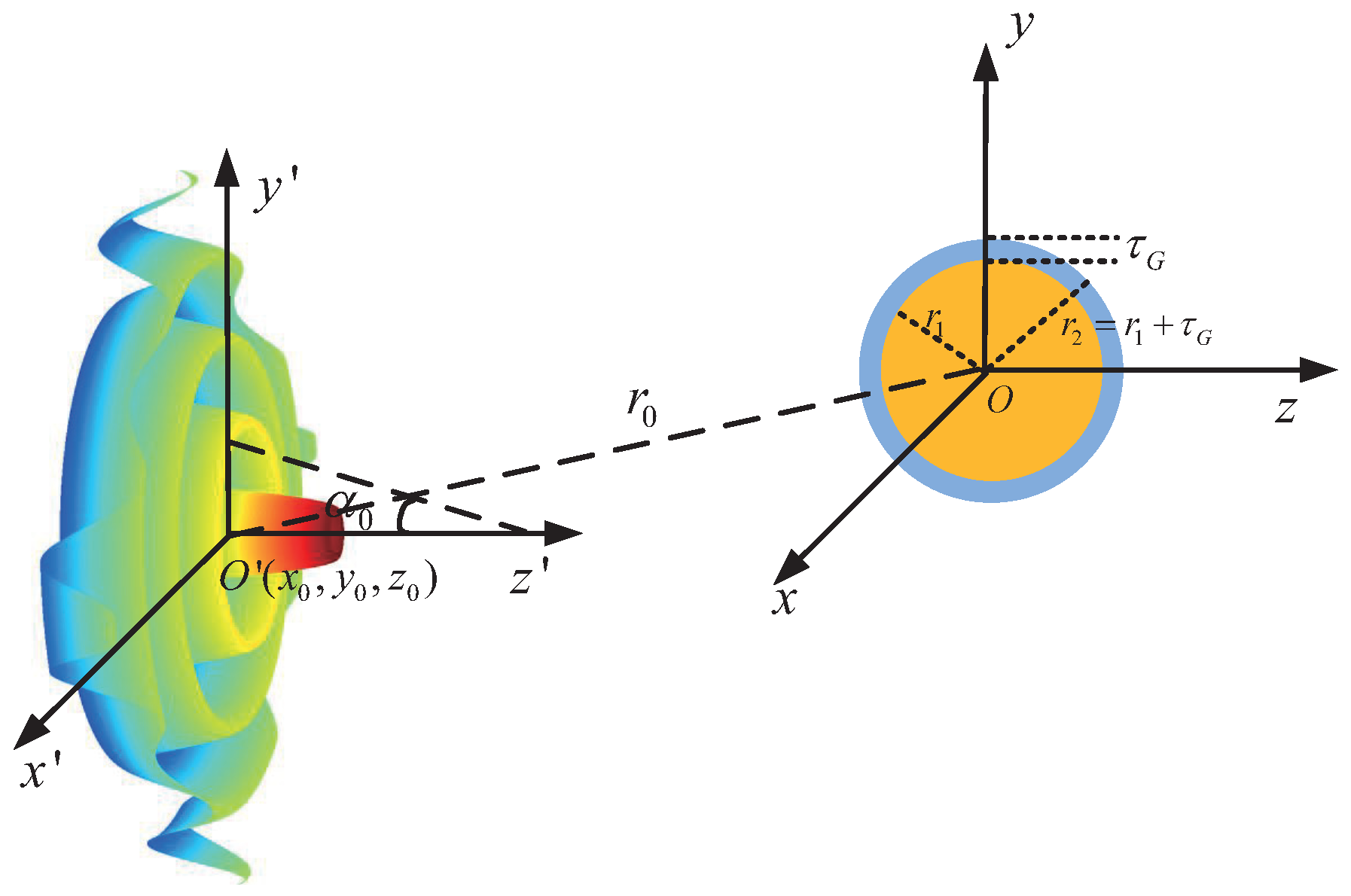
2. Theory
3. Numerical Results and Discussion
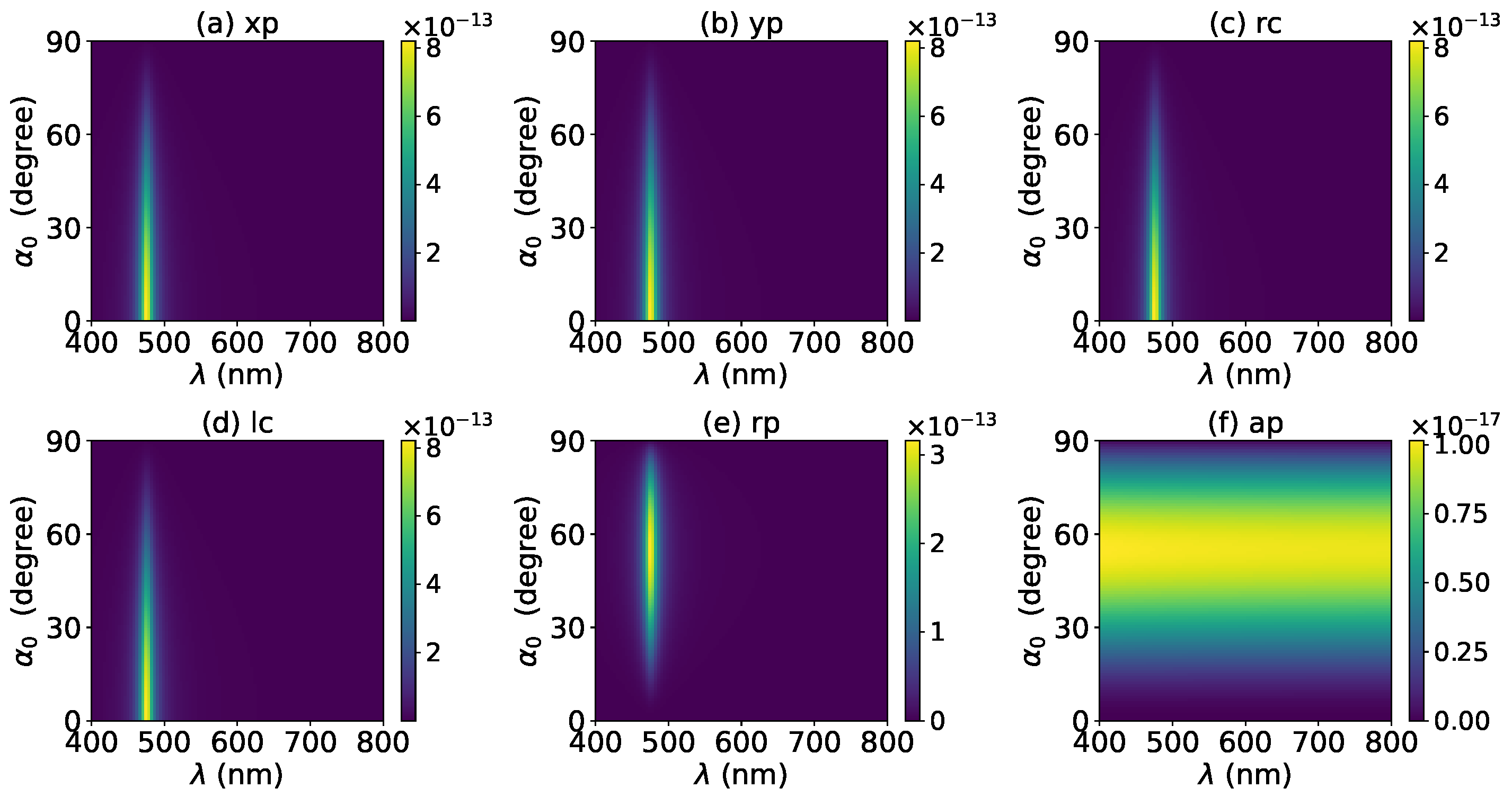
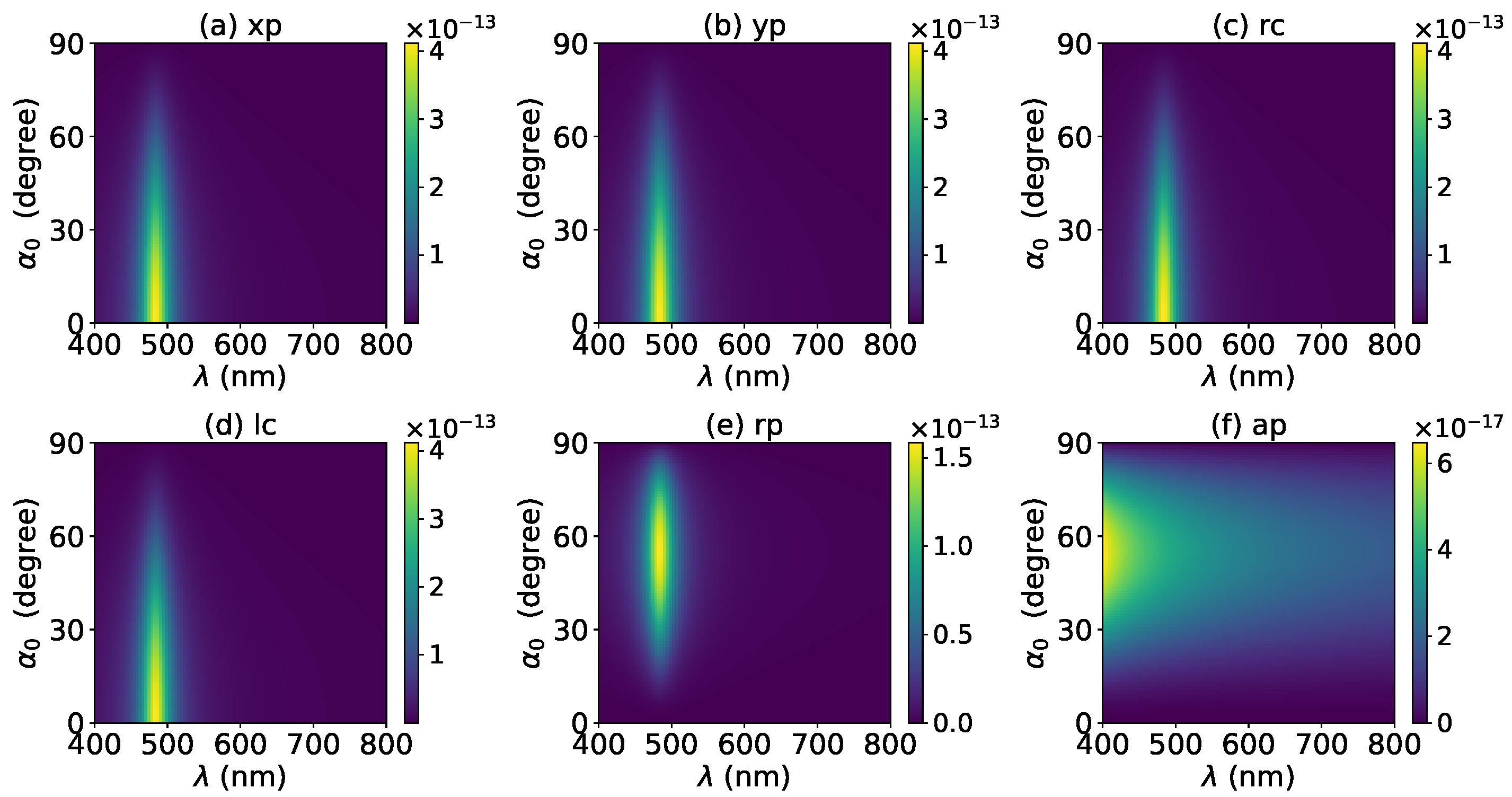
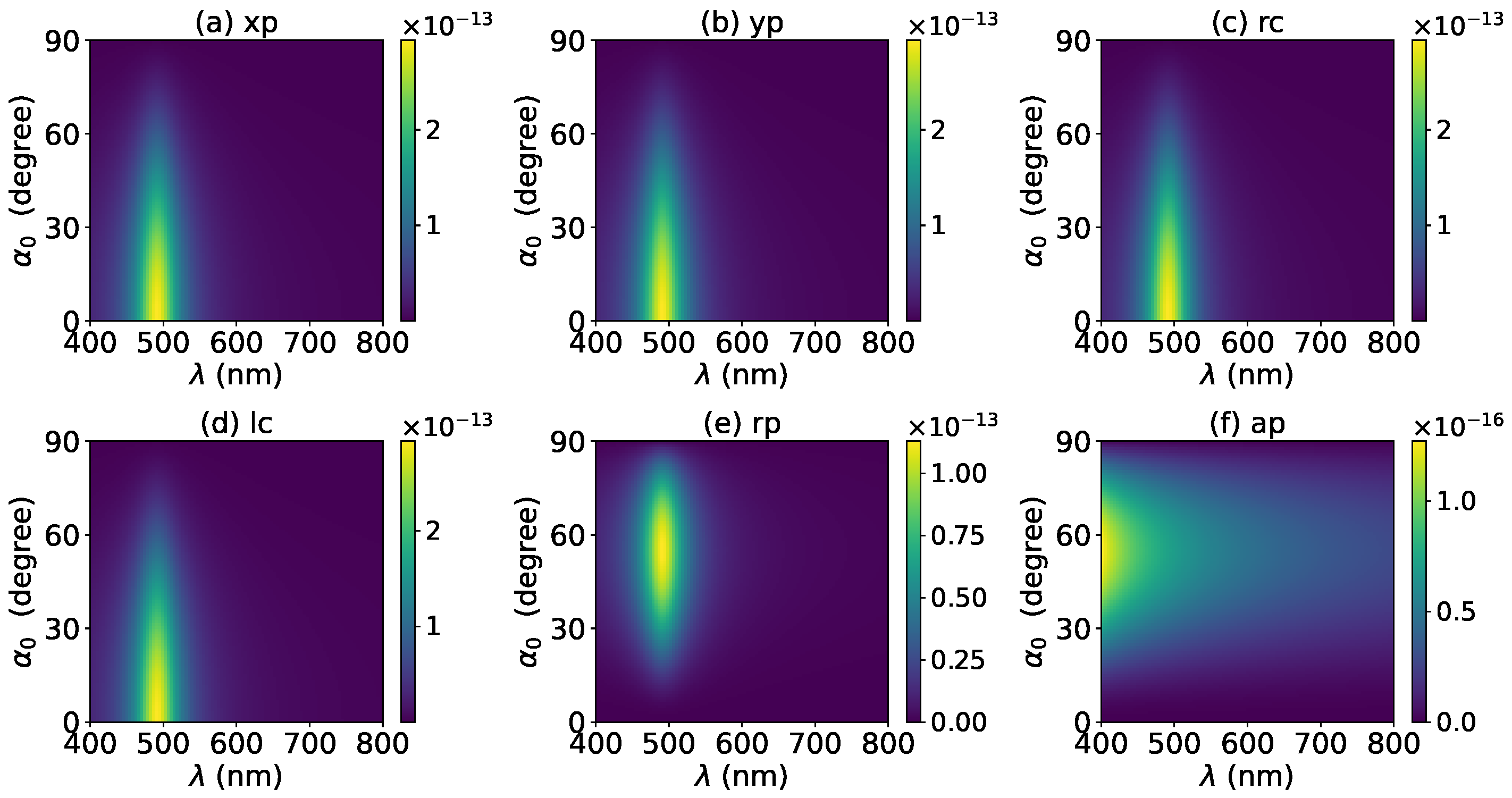
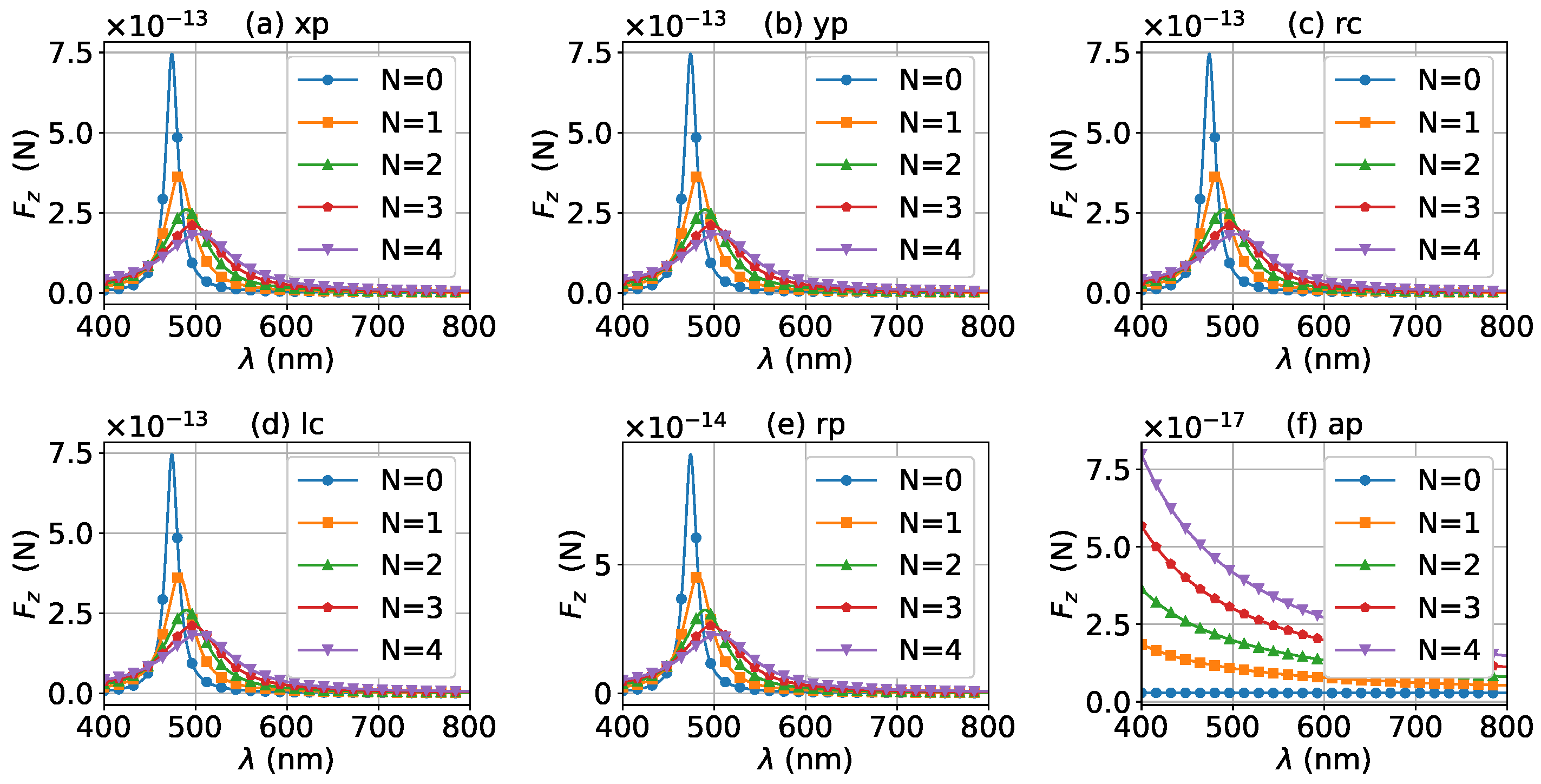
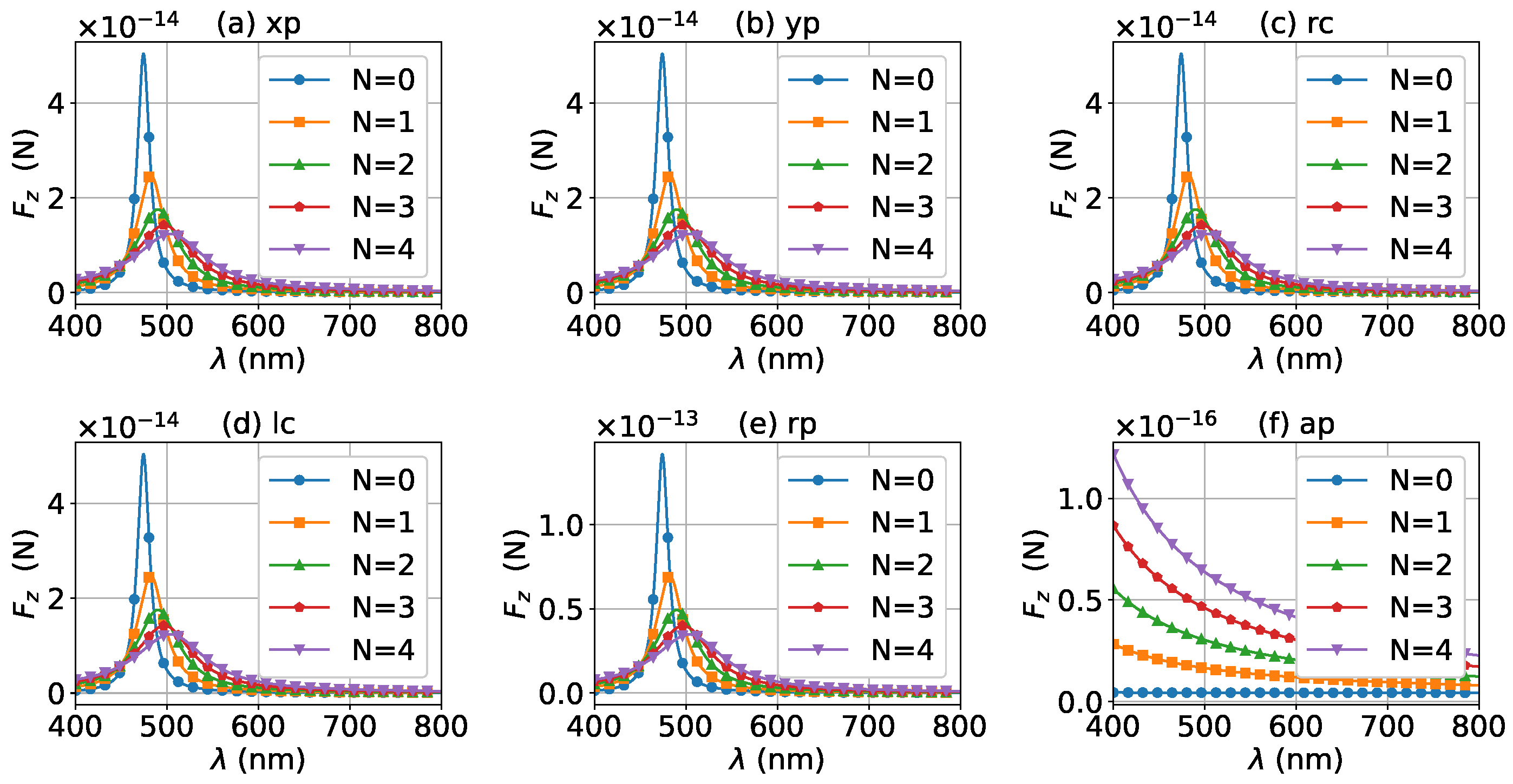
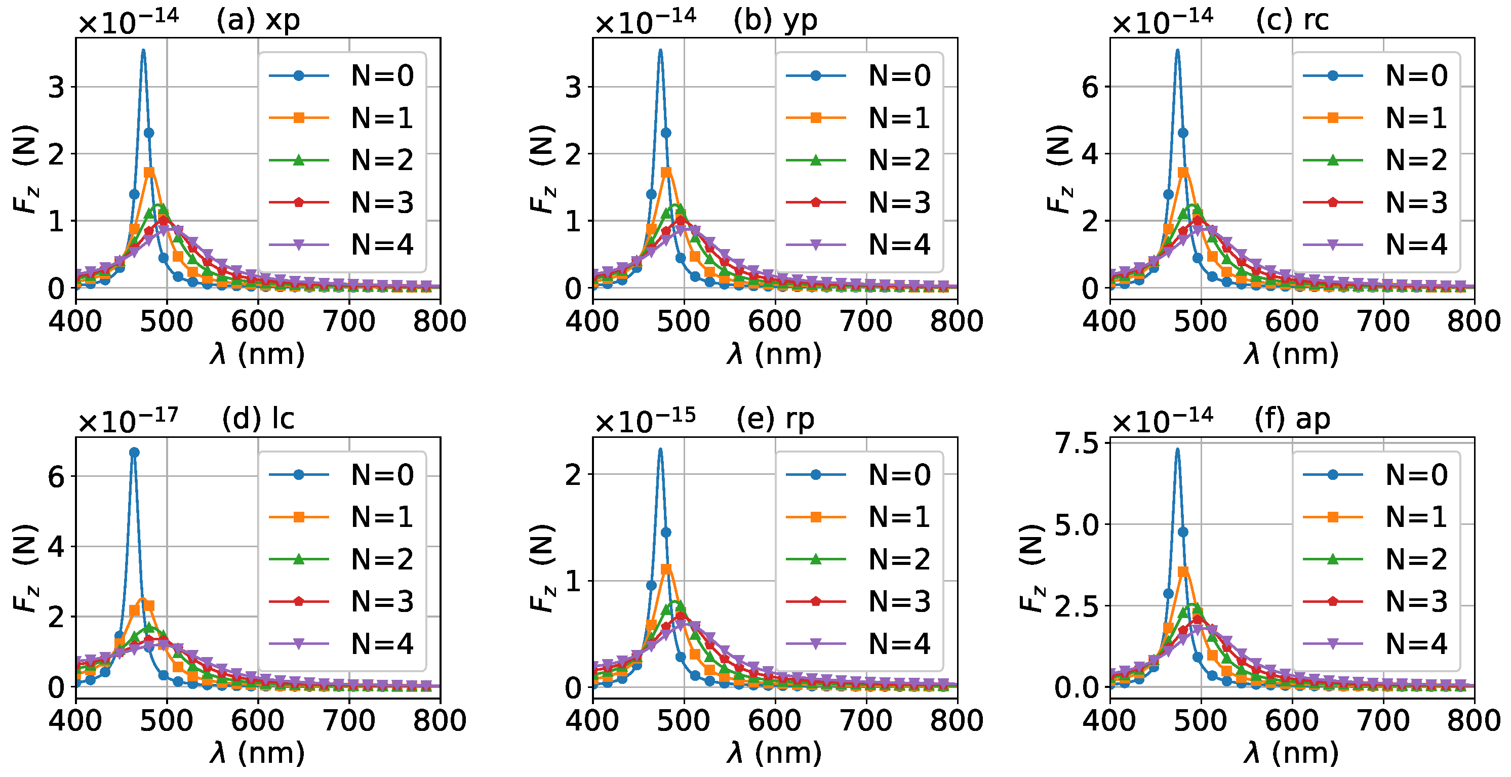
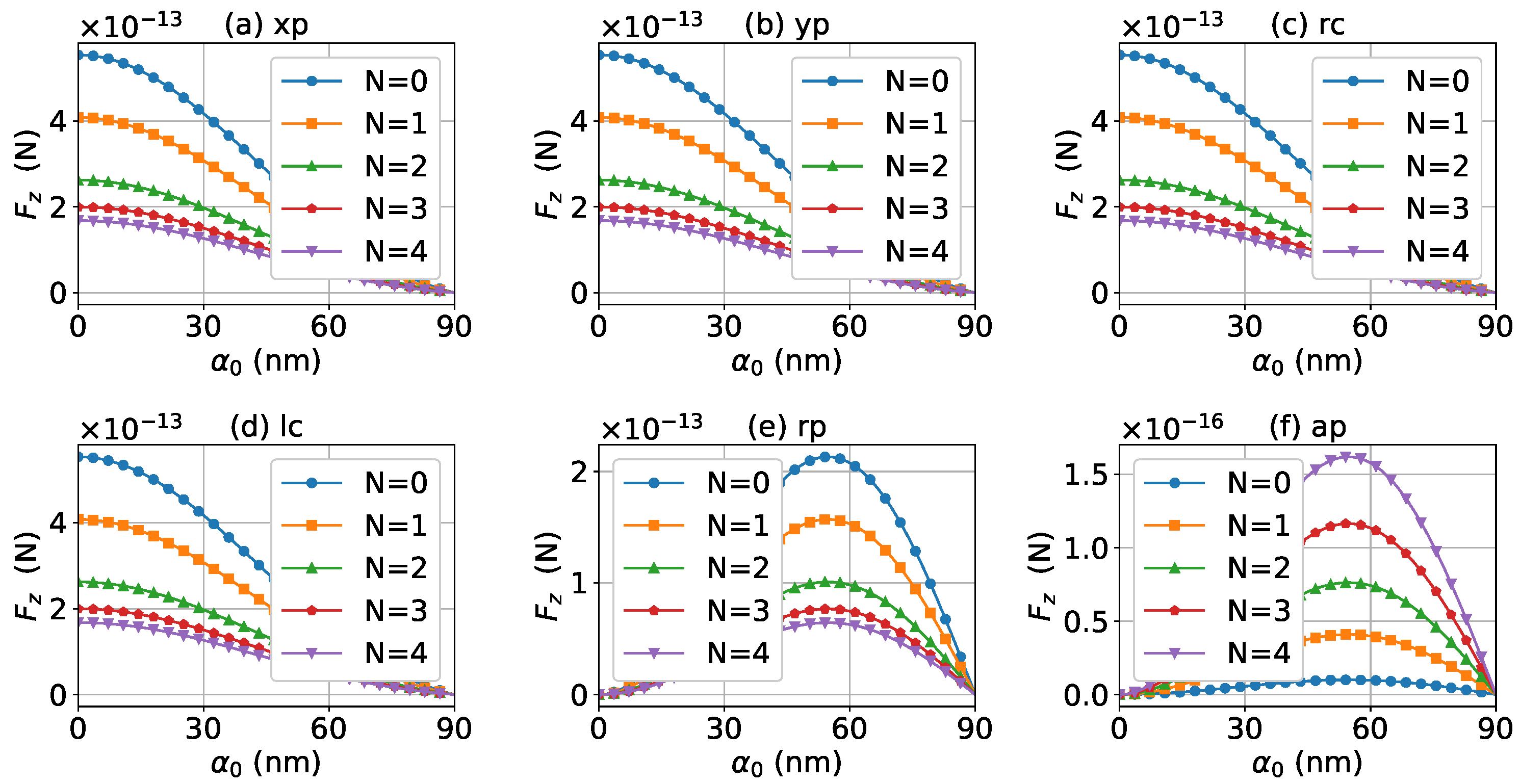
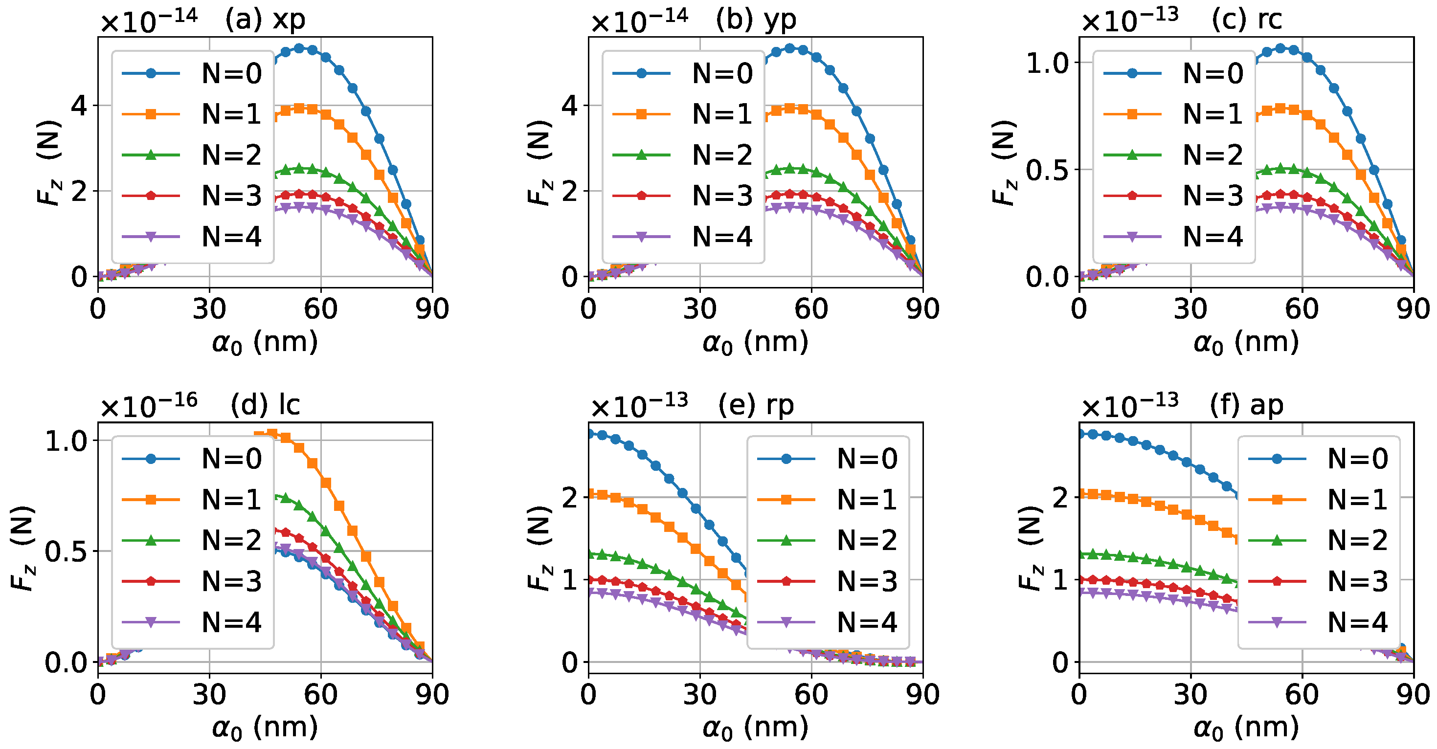
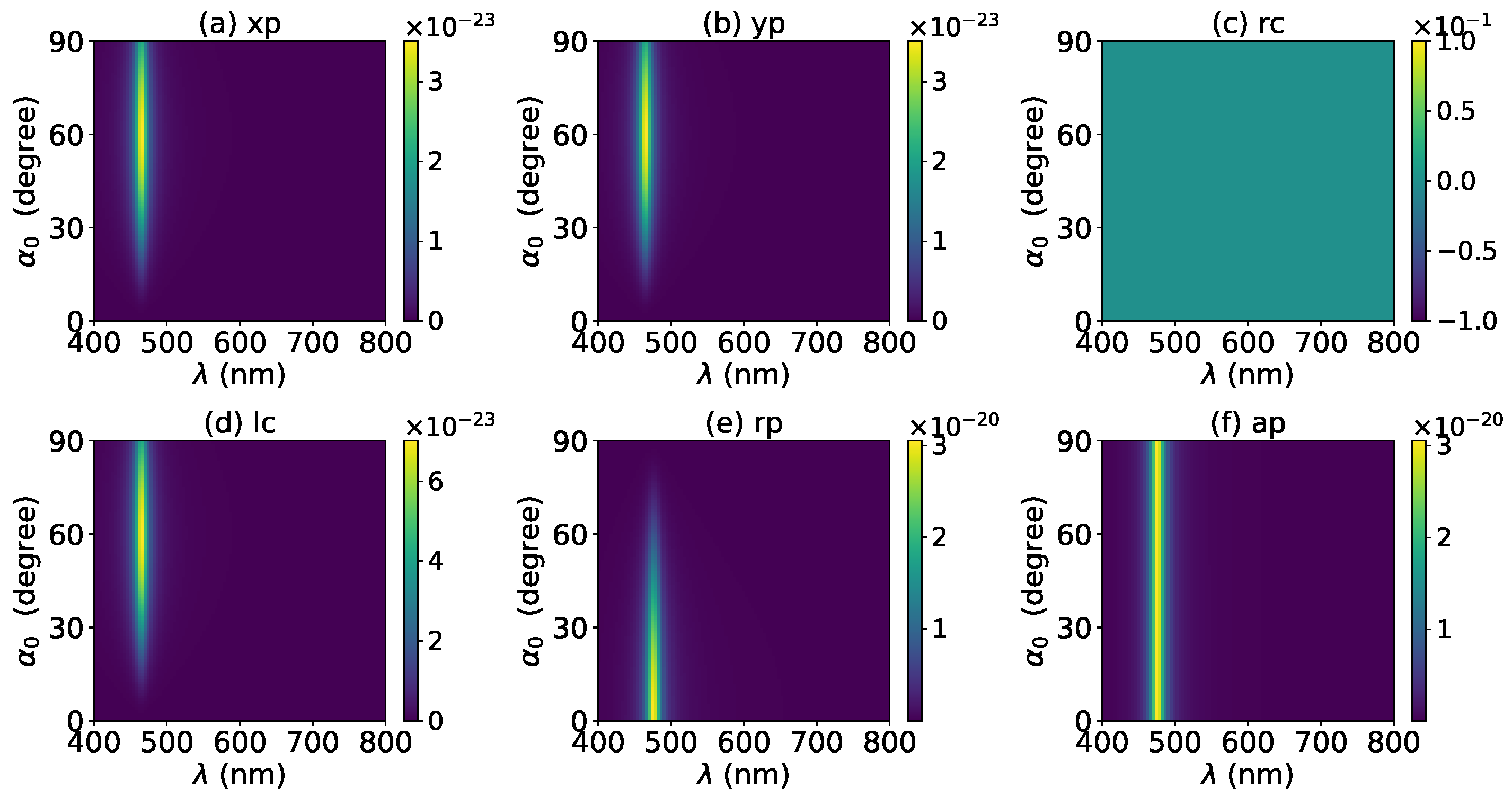
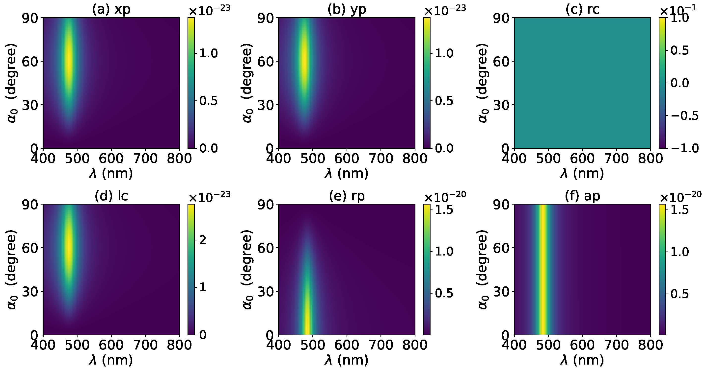
3.1. Optical Force
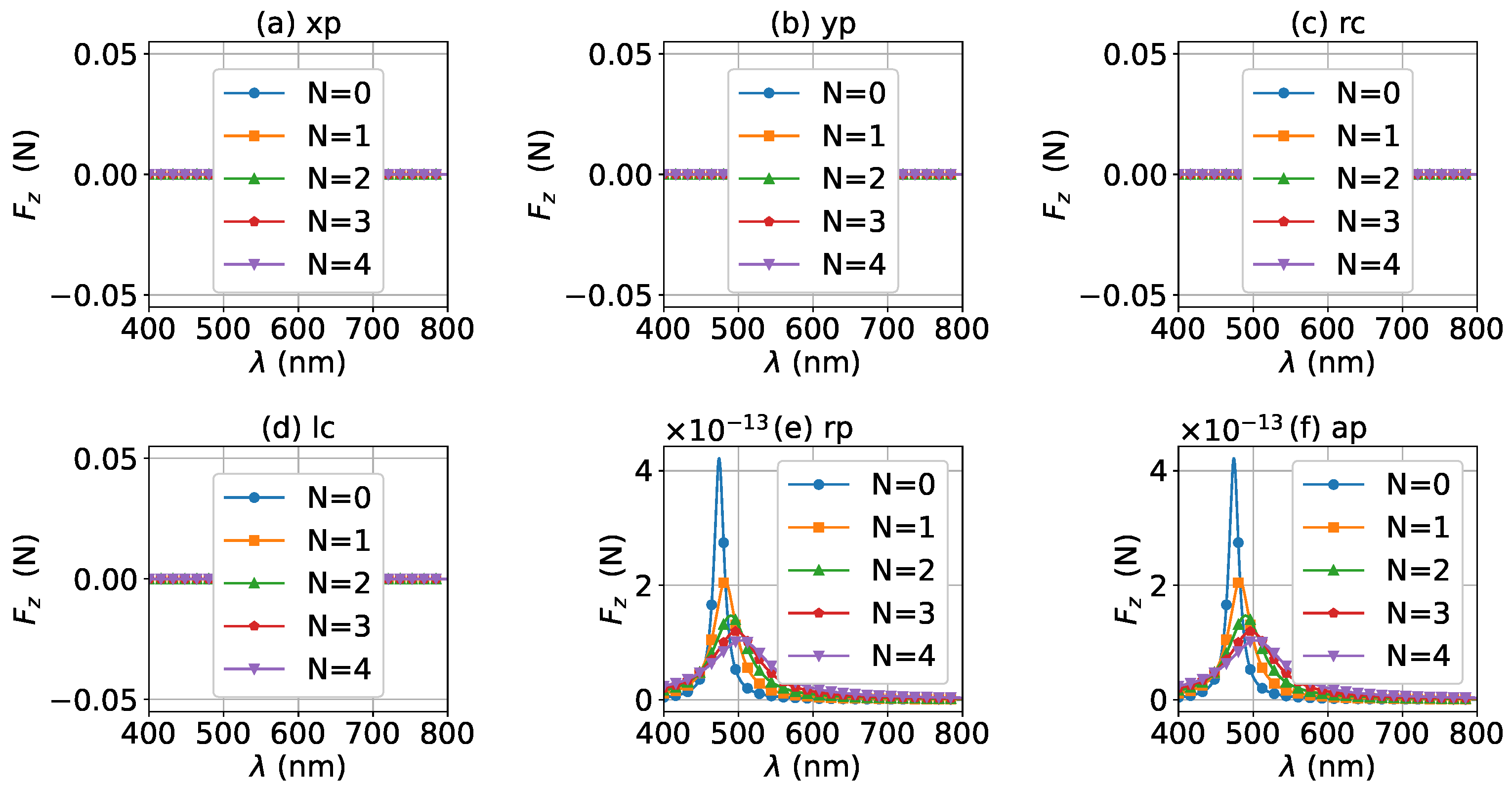
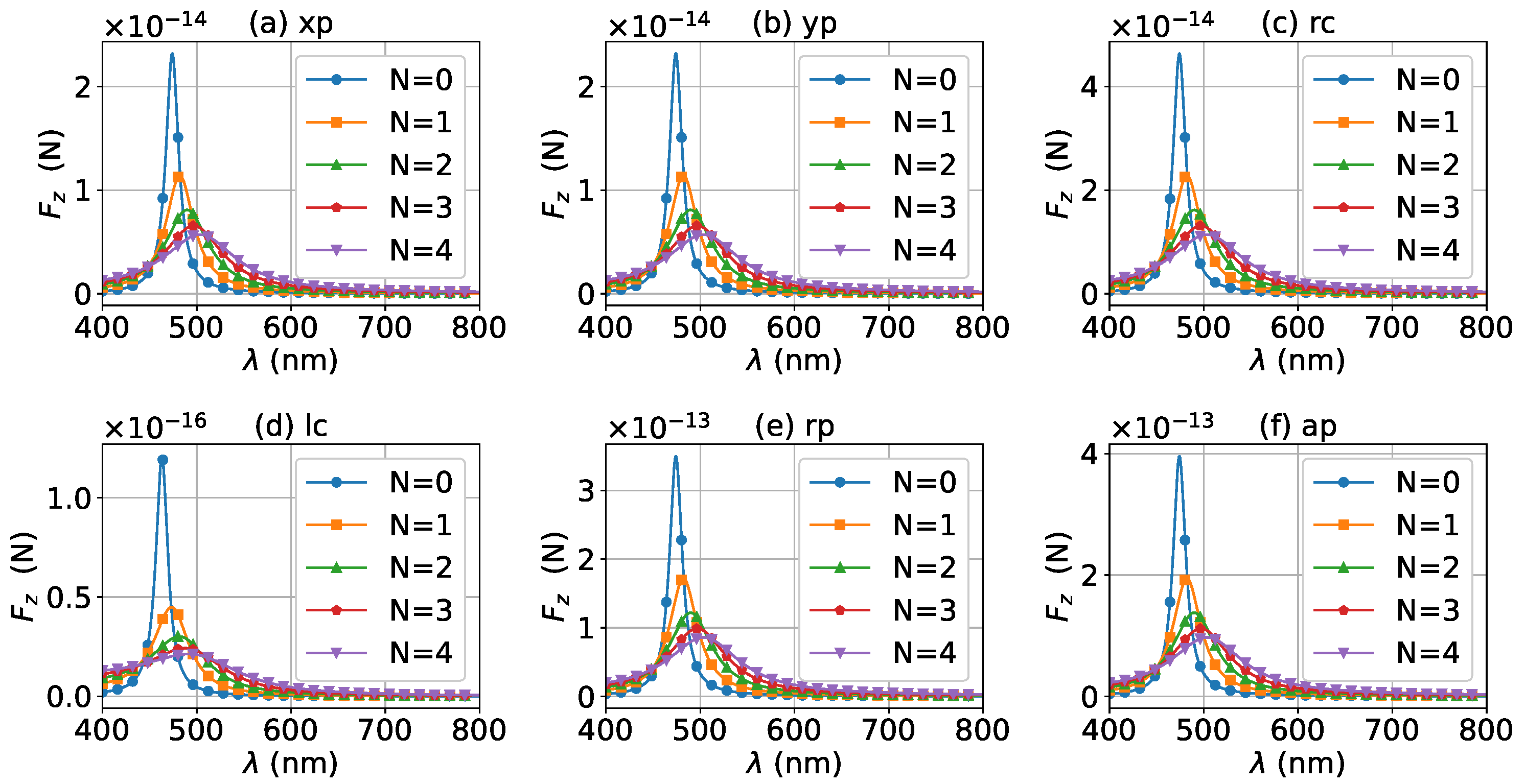
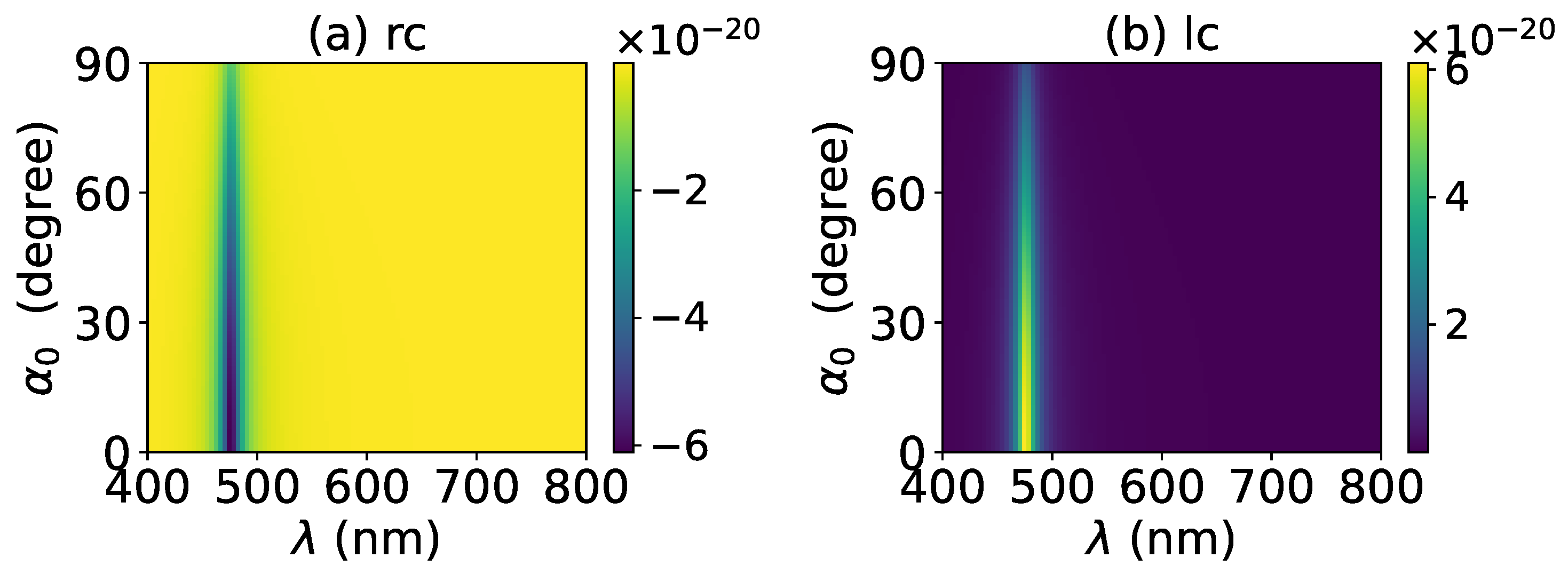
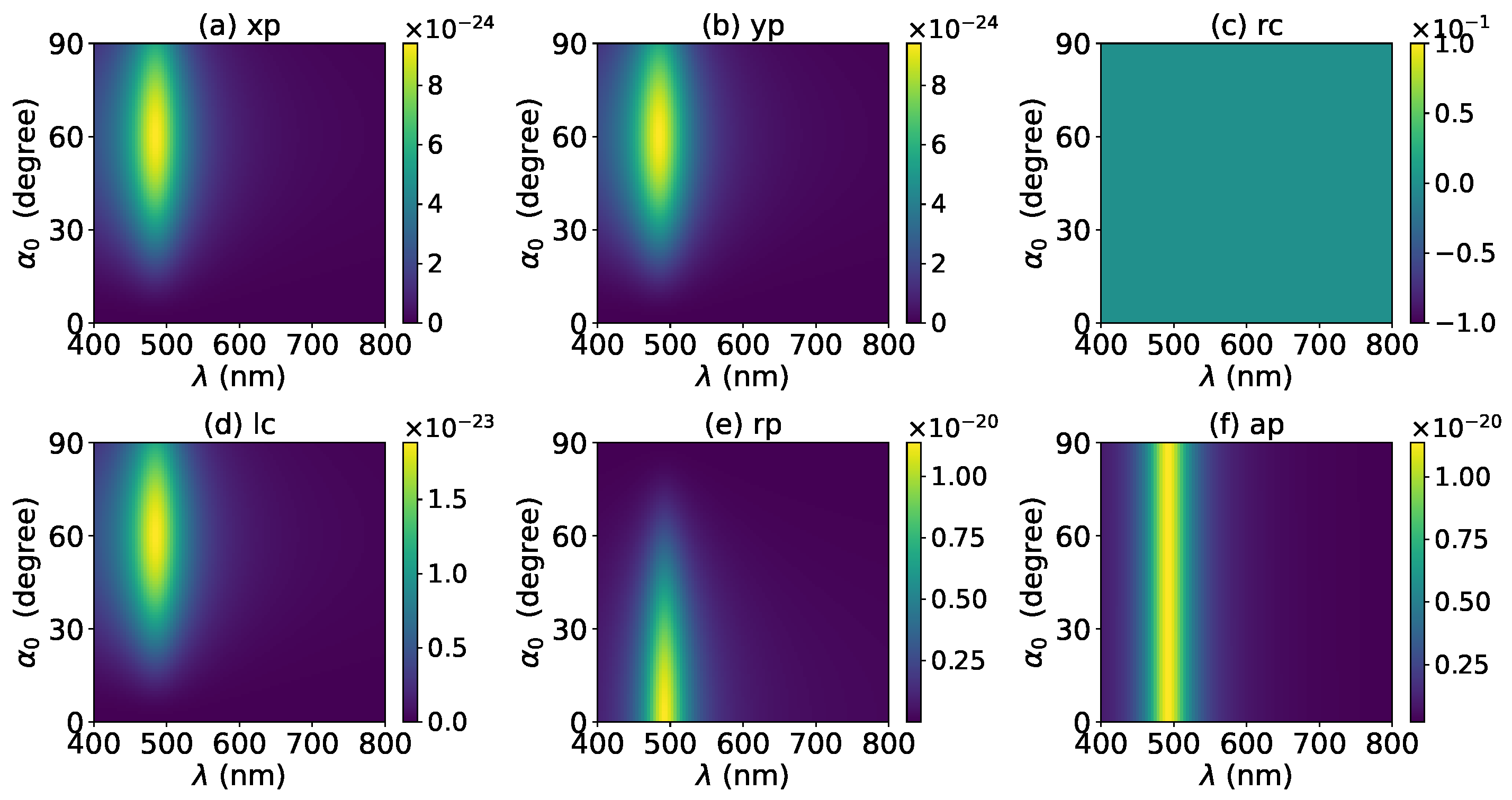
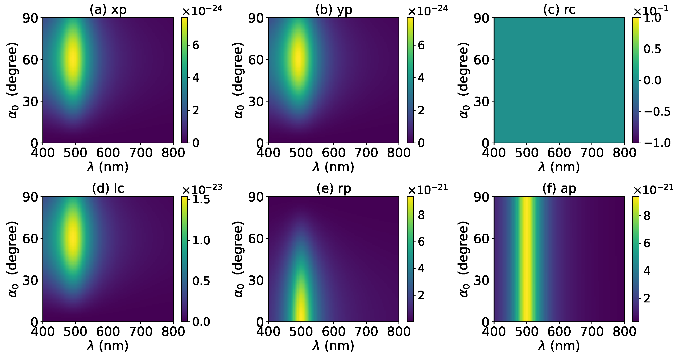
3.2. Optical Torque
4. Conclusions
Author Contributions
Funding
Institutional Review Board Statement
Informed Consent Statement
Data Availability Statement
Conflicts of Interest
Appendix A. Electric Fields of Vector Bessel Beams with Various Polarizations
- polarizationwhere with the amplitude of the plane wave forming the Bessel beam. is the -order Bessel function, and its argument has been omitted. and .
- polarization
- Circular polarizationwhere + and − correspond to left and right polarizations, respectively.
- Radial polarization
- Azimuthal polarization
Appendix B. BSCs for Vector Bessel Beam with Various Polarizations
- polarizationwhere, , and .
- polarization
- Circular polarization
- Radial polarization
- Azimuthal polarization
References
- Chen, M.; Huang, S.; Shao, W.; Liu, X. Optical force and torque on a dielectric Rayleigh particle by a circular Airy vortex beam. J. Quant. Spectrosc. Radiat. Transf. 2018, 208, 101–107. [Google Scholar] [CrossRef]
- Zhang, H.; Li, J.; Guo, M.; Duan, M.; Feng, Z.; Yang, W. Optical trapping two types of particles using a focused vortex beam. Optik 2018, 166, 138–146. [Google Scholar] [CrossRef]
- Chen, M.; Huang, S.; Liu, X.; Chen, Y.; Shao, W. Optical trapping and rotating of micro-particles using the circular Airy vortex beams. Appl. Phys. B 2019, 125, 184. [Google Scholar] [CrossRef]
- Rui, G.; Li, Y.; Gu, B.; Cui, Y.; Zhan, Q. Optical manipulation of nanoparticles with structured light. Thin Film Nanophotonics 2021, 139–177. [Google Scholar] [CrossRef]
- Durnin, J.; Miceli, J.J., Jr.; Eberly, J.H. Diffraction-free beams. Phys. Rev. Lett. 1987, 58, 1499–1501. [Google Scholar] [CrossRef]
- Bouchal, Z.; Wagner, J.; Chlup, M. Self-reconstruction of a distorted nondiffracting beam. Opt. Commun. 1998, 151, 207–211. [Google Scholar] [CrossRef]
- McGloin, D.; Dholakia, K. Bessel beams: Diffraction in a new light. Contemp. Phys. 2005, 46, 15–28. [Google Scholar] [CrossRef]
- Andrade, U.; Garcia, A.; Rocha, M. Bessel beam optical tweezers for manipulating superparamagnetic beads. Appl. Opt. 2021, 60, 3422–3429. [Google Scholar] [CrossRef]
- Chen, J.; Ng, J.; Lin, Z.; Chan, C.T. Optical pulling force. Nat. Photonics 2011, 5, 531–534. [Google Scholar] [CrossRef] [Green Version]
- Sukhov, S.; Dogariu, A. Negative nonconservative forces: Optical “tractor beams” for arbitrary objects. Phys. Rev. Lett. 2011, 107, 203602. [Google Scholar] [CrossRef]
- Novitsky, A.; Qiu, C.W.; Wang, H. Single gradientless light beam drags particles as tractor beams. Phys. Rev. Lett. 2011, 107, 279–281. [Google Scholar] [CrossRef] [PubMed] [Green Version]
- Ruffner, D.B.; Grier, D.G. Optical conveyors: A class of active tractor beams. Phys. Rev. Lett. 2012, 109, 163903. [Google Scholar] [CrossRef] [PubMed] [Green Version]
- Novitsky, A.; Qiu, C.W.; Lavrinenko, A. Material-independent and size-independent tractor beams for dipole objects. Phys. Rev. Lett. 2012, 109, 507–512. [Google Scholar] [CrossRef] [PubMed] [Green Version]
- Mitri, F.G. Near-field single tractor-beam acoustical tweezers. Appl. Phys. Lett. 2013, 103, 2140–2143. [Google Scholar] [CrossRef]
- Shvedov, V.; Davoyan, A.R.; Hnatovsky, C.; Engheta, N.; Krolikowski, W. A long-range polarization-controlled optical tractor beam. Nat. Photonics 2014, 8, 846. [Google Scholar] [CrossRef]
- Mitri, F.G. Single Bessel tractor-beam tweezers. Wave Motion 2014, 51, 986–993. [Google Scholar] [CrossRef] [Green Version]
- Wang, N.; Lu, W.; Ng, J.; Lin, Z. Optimized optical “tractor beam” for core-shell nanoparticles. Opt. Lett. 2014, 39, 2399–2402. [Google Scholar] [CrossRef]
- Carretero, L.; Acebal, P.; Blaya, S. Three-dimensional analysis of optical forces generated by an active tractor beam using radial polarization. Opt. Express 2014, 22, 3284–3295. [Google Scholar] [CrossRef]
- Selim, G.M. Optical Tractor Beam with Chiral Light. Phys. Rev. A 2015, 91, 061801. [Google Scholar]
- Gao, D.; Novitsky, A.; Zhang, T.; Cheong, F.C.; Gao, L.; Lim, C.T.; Luk’Yanchuk, B.; Qiu, C.W. Unveiling the correlation between non-diffracting tractor beam and its singularity in Poynting vector. Laser Photonics Rev. 2015, 9, 75–82. [Google Scholar] [CrossRef]
- Yevick, A.; Ruffner, D.B.; Grier, D.G. Tractor beams in the Rayleigh limit. Phys. Rev. A 2016, 93, 043807. [Google Scholar] [CrossRef] [Green Version]
- Mitri, F.G.; Li, R.X.; Yang, R.; Guo, L.X.; Ding, C.Y. Optical pulling force on a magneto-dielectric Rayleigh sphere in Bessel tractor polarized beams. J. Quant. Spectrosc. Radiat. Transf. 2016, 184, 360–381. [Google Scholar] [CrossRef]
- Novitsky, A.; Gao, D.; Gorlach, A.A.; Qiu, C.W.; Lavrinenko, A.V. Non-diffractive tractor beams. In Proceedings of the 19th International Conference on Transparent Optical Networks (ICTON), Girona, Spain, 2–6 July 2017; pp. 1–4. [Google Scholar]
- Mitri, F.G. Optical Bessel tractor beam on active dielectric Rayleigh prolate and oblate spheroids. J. Opt. Soc. Am. B Opt. Phys. 2017, 34, 899. [Google Scholar] [CrossRef]
- Novitsky, A.; Ding, W.; Wang, M.; Gao, D.; Lavrinenko, A.V.; Qiu, C.W. Pulling cylindrical particles using a soft-nonparaxial tractor beam. Sci. Rep. 2017, 7, 652. [Google Scholar] [CrossRef] [Green Version]
- Kajorndejnukul, V.; Ding, W.; Sukhov, S.; Qiu, C.W.; Dogariu, A. Linear momentum increase and negative optical forces at dielectric interface. Nat. Photonics 2013, 7, 787–790. [Google Scholar] [CrossRef] [Green Version]
- Qiu, C.W.; Ding, W.; Mahdy, M.R.C.; Gao, D.; Zhang, T.; Cheong, F.C.; Dogariu, A.; Wang, Z.; Lim, C.T. Photon momentum transfer in inhomogeneous dielectric mixtures and induced tractor beams. Light Sci. Appl. 2015, 4, e278. [Google Scholar] [CrossRef] [Green Version]
- Mizrahi, A.; Fainman, Y. Negative radiation pressure on gain medium structures. Opt. Lett. 2010, 35, 3405–3407. [Google Scholar] [CrossRef]
- Mitri, F.G. Negative axial radiation force on a fluid and elastic spheres illuminated by a high-order Bessel beam of progressive waves. J. Phys. A Math. Theor. 2009, 42, 1947–1957. [Google Scholar] [CrossRef]
- Mitri, F.G.; Li, R.X.; Guo, L.X.; Ding, C.Y. Optical tractor Bessel polarized beams. J. Quant. Spectrosc. Radiat. Transf. 2016, 187, 97–115. [Google Scholar] [CrossRef]
- Li, R.; Li, P.; Zhang, J.; Ding, C.; Cui, Z. Optical Bessel tractor polarized beams on a charged sphere of arbitrary size. J. Quant. Spectrosc. Radiat. Transf. 2018, 219, 186–198. [Google Scholar] [CrossRef]
- Bai, J.; Wu, Z.; Ge, C.; Li, Z.; Qu, T.; Shang, Q. Analytical description of lateral binding force exerted on bi-sphere induced by high-order Bessel beams. J. Quant. Spectrosc. Radiat. Transf. 2018, 214, 71–81. [Google Scholar] [CrossRef]
- Wang, H.; Wang, J.; Dong, W.; Han, Y.; Ambrosio, L.A.; Liu, L. Theoretical prediction of photophoretic force on a dielectric sphere illuminated by a circularly symmetric high-order Bessel beam: On-axis case. Opt. Express 2021, 29, 26894–26908. [Google Scholar] [CrossRef] [PubMed]
- Li, H.; Cao, Y.; Zhou, L.M.; Xu, X.; Zhu, T.; Shi, Y.; Qiu, C.W.; Ding, W. Optical pulling forces and their applications. Adv. Opt. Photonics 2020, 12, 288–366. [Google Scholar] [CrossRef]
- Ambrosio, L.A.; Gouesbet, G. On longitudinal radiation pressure cross-sections in the generalized Lorenz–Mie theory and their numerical relationship with the dipole theory of forces. JOSA B 2021, 38, 825–833. [Google Scholar] [CrossRef]
- Chen, H.; Gao, L.; Zhong, C.; Yuan, G.; Huang, Y.; Yu, Z.; Cao, M.; Wang, M. Optical pulling force on nonlinear nanoparticles with gain. AIP Adv. 2020, 10, 015131. [Google Scholar] [CrossRef]
- Mitri, F.G. Optical Bessel beam illumination of a subwavelength prolate gold (Au) spheroid coated by a layer of plasmonic material: Radiation force, spin and orbital torques. J. Phys. Commun. 2017, 1, 015001. [Google Scholar] [CrossRef] [Green Version]
- Li, R.; Ding, C.; Mitri, F.G. Optical spin torque induced by vector Bessel (vortex) beams with selective polarizations on a light-absorptive sphere of arbitrary size. J. Quant. Spectrosc. Radiat. Transf. 2017, 196, 53–68. [Google Scholar] [CrossRef]
- Yang, R.; Li, R.; Qin, S.; Ding, C.; Mitri, F.G. Direction reversal of the optical spin torque on a Rayleigh absorptive sphere in vector Bessel polarized beams. J. Opt. 2017, 19, 025602. [Google Scholar] [CrossRef]
- Mitri, F.G. Reverse orbiting and spinning of a Rayleigh dielectric spheroid in a J0 Bessel optical beam. J. Opt. Soc. Am. B Opt. Phys. 2017, 34, 2169. [Google Scholar] [CrossRef]
- Mitri, F.G. Negative optical spin torque wrench of a non-diffracting non-paraxial fractional Bessel vortex beam. J. Quant. Spectrosc. Radiat. Transf. 2016, 182, 172–179. [Google Scholar] [CrossRef] [Green Version]
- Mayer, K.M.; Hafner, J.H. Localized surface plasmon resonance sensors. Chem. Rev. 2011, 111, 3828–3857. [Google Scholar] [CrossRef] [PubMed]
- Szunerits, S.; Boukherroub, R. Sensing using localised surface plasmon resonance sensors. Chem. Commun. 2012, 48, 8999–9010. [Google Scholar] [CrossRef] [PubMed]
- El Barghouti, M.; Akjouj, A.; Mir, A. Effect of graphene layer on the localized surface plasmon resonance (LSPR) and the sensitivity in periodic nanostructure. Photonics Nanostruct.-Fundam. Appl. 2018, 31, 107–114. [Google Scholar] [CrossRef]
- Bravin, C.; Amendola, V. Plasmonic Absorption in Antigen-Induced Aggregated Gold Nanoparticles: Toward a Figure of Merit for Optical Nanosensors. ACS Appl. Nano Mater. 2021. [Google Scholar] [CrossRef]
- Yildirim, D.U.; Ghobadi, A.; Ozbay, E. Nanosensors Based on Localized Surface Plasmon Resonance. In Plasmonic Sensors and Their Applications; Wiley Online Library: Hoboken, NJ, USA, 2021; pp. 23–54. [Google Scholar]
- Hutter, E.; Maysinger, D. Gold nanoparticles and quantum dots for bioimaging. Microsc. Res. Tech. 2011, 74, 592–604. [Google Scholar] [CrossRef]
- Ou, X.; Liu, Y.; Zhang, M.; Hua, L.; Zhan, S. Plasmonic gold nanostructures for biosensing and bioimaging. Microchim. Acta 2021, 188, 304. [Google Scholar] [CrossRef]
- Si, P.; Razmi, N.; Nur, O.; Solanki, S.; Pandey, C.M.; Gupta, R.K.; Malhotra, B.D.; Willander, M.; de la Zerda, A. Gold nanomaterials for optical biosensing and bioimaging. Nanoscale Adv. 2021, 3, 2679–2698. [Google Scholar] [CrossRef]
- Andreiuk, B.; Nicolson, F.; Clark, L.M.; Panikkanvalappil, S.R.; Kenry, R.M.; Harmsen, S.; Kircher, M.F. Design and synthesis of gold nanostars-based SERS nanotags for bioimaging applications. Nanotheranostics 2022, 6, 10. [Google Scholar] [CrossRef]
- Singh, P.; Pandit, S.; Mokkapati, V.; Garg, A.; Ravikumar, V.; Mijakovic, I. Gold nanoparticles in diagnostics and therapeutics for human cancer. Int. J. Mol. Sci. 2018, 19, 1979. [Google Scholar] [CrossRef]
- Irshad, A.; Zahid, M.; Husnain, T.; Rao, A.Q.; Sarwar, N.; Hussain, I. A proactive model on innovative biomedical applications of gold nanoparticles. Appl. Nanosci. 2020, 10, 2453–2465. [Google Scholar] [CrossRef]
- Hu, X.; Zhang, Y.; Ding, T.; Liu, J.; Zhao, H. Multifunctional gold nanoparticles: A novel nanomaterial for various medical applications and biological activities. Front. Bioeng. Biotechnol. 2020, 8, 990. [Google Scholar] [CrossRef] [PubMed]
- Gordon, R. Biosensing with nanoaperture optical tweezers. Opt. Laser Technol. 2019, 109, 328–335. [Google Scholar] [CrossRef]
- Wu, Y.; Ali, M.R.; Chen, K.; Fang, N.; El-Sayed, M.A. Gold nanoparticles in biological optical imaging. Nano Today 2019, 24, 120–140. [Google Scholar] [CrossRef]
- Phummirat, P.; Mann, N.; Preece, D. Applications of Optically Controlled Gold Nanostructures in Biomedical Engineering. Front. Bioeng. Biotechnol. 2021, 8. [Google Scholar] [CrossRef] [PubMed]
- Farokhnezhad, M.; Esmaeilzadeh, M. Graphene coated gold nanoparticles: An emerging class of nanoagents for photothermal therapy applications. Phys. Chem. Chem. Phys. 2019, 21, 18352–18362. [Google Scholar] [CrossRef]
- Raad, S.H.; Atlasbaf, Z. Tunable optical meta-surface using graphene-coated spherical nanoparticles. AIP Adv. 2019, 9, 075224. [Google Scholar] [CrossRef] [Green Version]
- Chen, H.; Huang, Y. Tunable optical force on nonlinear graphene-wrapped nanoparticles. Phys. Lett. A 2020, 384, 126733. [Google Scholar] [CrossRef]
- Yang, Y.; Shi, Z.; Li, J.; Li, Z.Y. Optical forces exerted on a graphene-coated dielectric particle by a focused Gaussian beam. Photonics Res. 2016, 4, 65–69. [Google Scholar] [CrossRef]
- Hou, X.; Gao, D.; Gao, L. Graphene-tuned optical manipulation on microparticle by Bessel beam. AIP Adv. 2019, 9, 035154. [Google Scholar] [CrossRef] [Green Version]
- Pinchuk, A.; Kreibig, U.; Hilger, A. Optical properties of metallic nanoparticles: Influence of interface effects and interband transitions. Surf. Sci. 2004, 557, 269–280. [Google Scholar] [CrossRef]
- Schedin, F.; Lidorikis, E.; Lombardo, A.; Kravets, V.G.; Geim, A.K.; Grigorenko, A.N.; Novoselov, K.S.; Ferrari, A.C. Surface-enhanced Raman spectroscopy of graphene. ACS Nano 2010, 4, 5617–5626. [Google Scholar] [CrossRef] [PubMed]
- Mitri, F.G.; Li, R.X.; Guo, L.X.; Ding, C.Y. Resonance scattering of a dielectric sphere illuminated by electromagnetic Bessel non-diffracting (vortex) beams with arbitrary incidence and selective polarizations. Ann. Phys. 2015, 361, 120–147. [Google Scholar] [CrossRef]
- Chen, J.; Ng, J.; Wang, P.; Lin, Z. Analytical partial wave expansion of vector Bessel beam and its application to optical binding. Opt. Lett. 2010, 35, 1674–1676. [Google Scholar] [CrossRef] [PubMed]
- Gouesbet, G.; Gréhan, G. Generalized Lorenz-Mie Theories; Springer: Berlin/Heidelberg, Germany, 2011; pp. 277–333. [Google Scholar]
- Zambrana-Puyalto, X.; Molina-Terriza, G. The role of the angular momentum of light in Mie scattering. Excitation of dielectric spheres with Laguerre-Gaussian modes. J. Quant. Spectrosc. Radiat. Transf. 2013, 126, 50–55. [Google Scholar] [CrossRef] [Green Version]


Publisher’s Note: MDPI stays neutral with regard to jurisdictional claims in published maps and institutional affiliations. |
© 2022 by the authors. Licensee MDPI, Basel, Switzerland. This article is an open access article distributed under the terms and conditions of the Creative Commons Attribution (CC BY) license (https://creativecommons.org/licenses/by/4.0/).
Share and Cite
Yan, B.; Ling, X.; Li, R.; Zhang, J.; Liu, C. Optical Force and Torque on a Graphene-Coated Gold Nanosphere by a Vector Bessel Beam. Micromachines 2022, 13, 456. https://doi.org/10.3390/mi13030456
Yan B, Ling X, Li R, Zhang J, Liu C. Optical Force and Torque on a Graphene-Coated Gold Nanosphere by a Vector Bessel Beam. Micromachines. 2022; 13(3):456. https://doi.org/10.3390/mi13030456
Chicago/Turabian StyleYan, Bing, Xiulan Ling, Renxian Li, Jianyong Zhang, and Chenhua Liu. 2022. "Optical Force and Torque on a Graphene-Coated Gold Nanosphere by a Vector Bessel Beam" Micromachines 13, no. 3: 456. https://doi.org/10.3390/mi13030456