
Review of Electrothermal Micromirrors


Abstract
:1. Introduction
2. Thermal Effects for Actuation
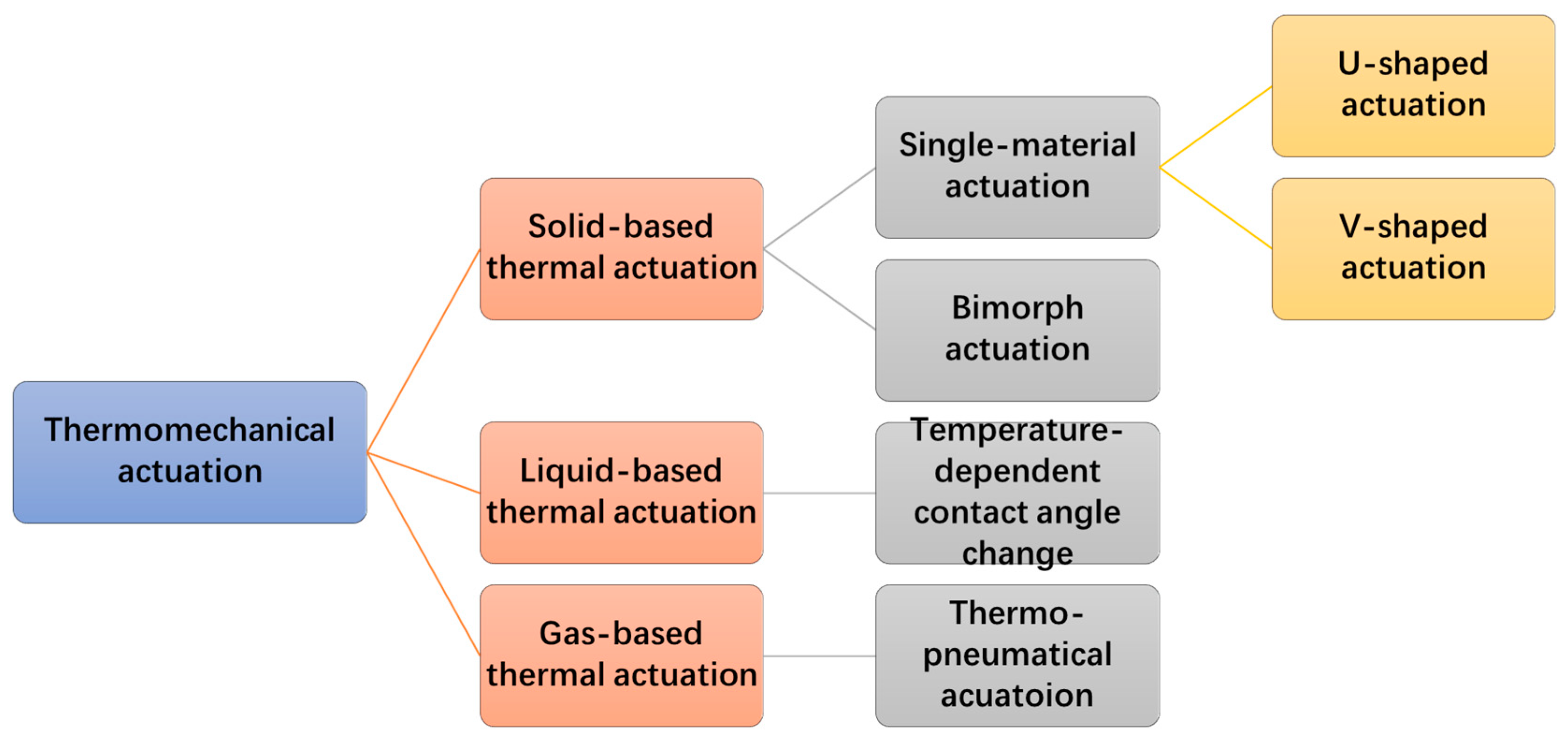
3. Electrothermal Action Mechanisms
3.1. Solid-Based Thermal Actuation
3.1.1. Single-Material Solid Thermal Actuators
Hot-Cold Arm Actuators
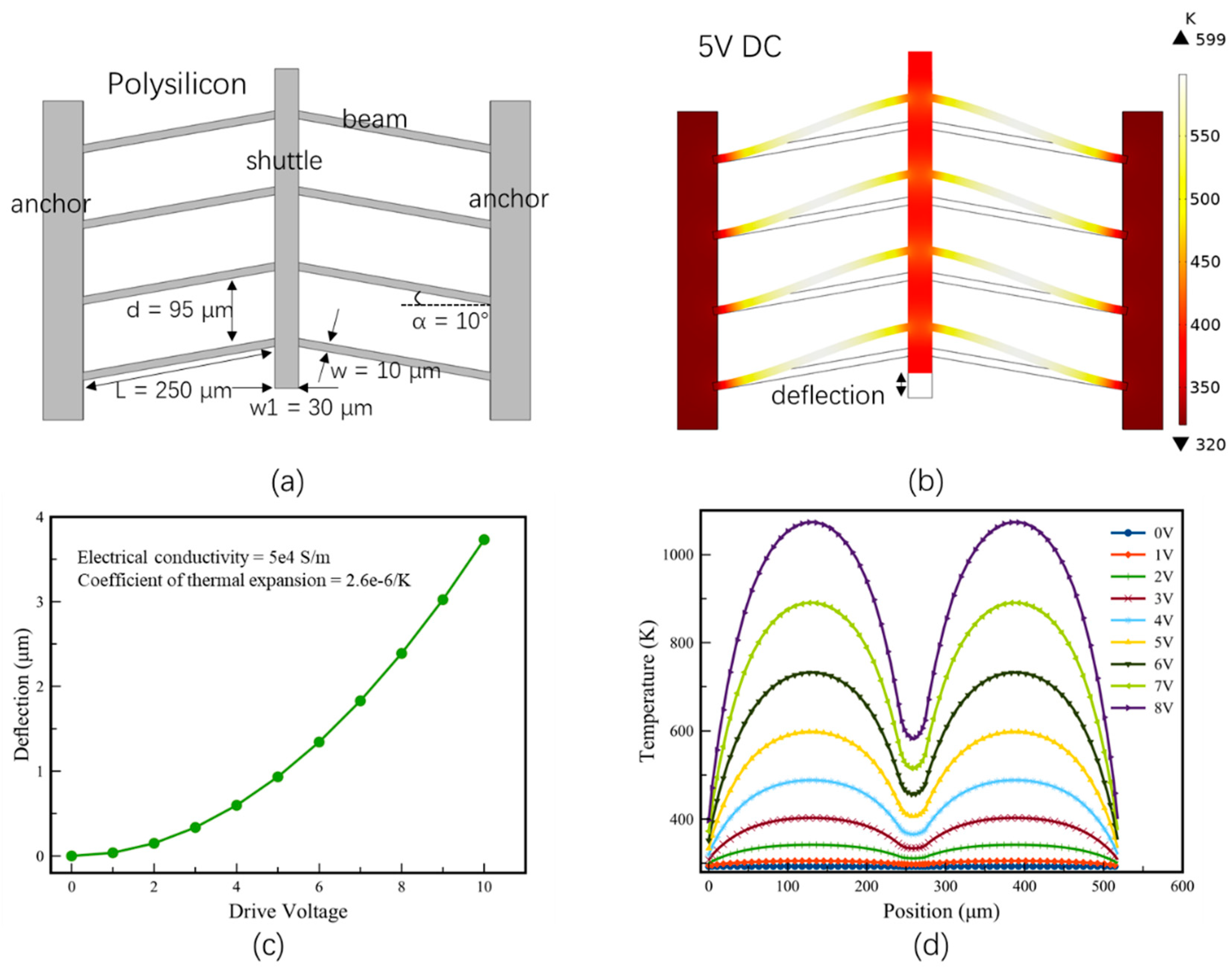
Chevron Actuators
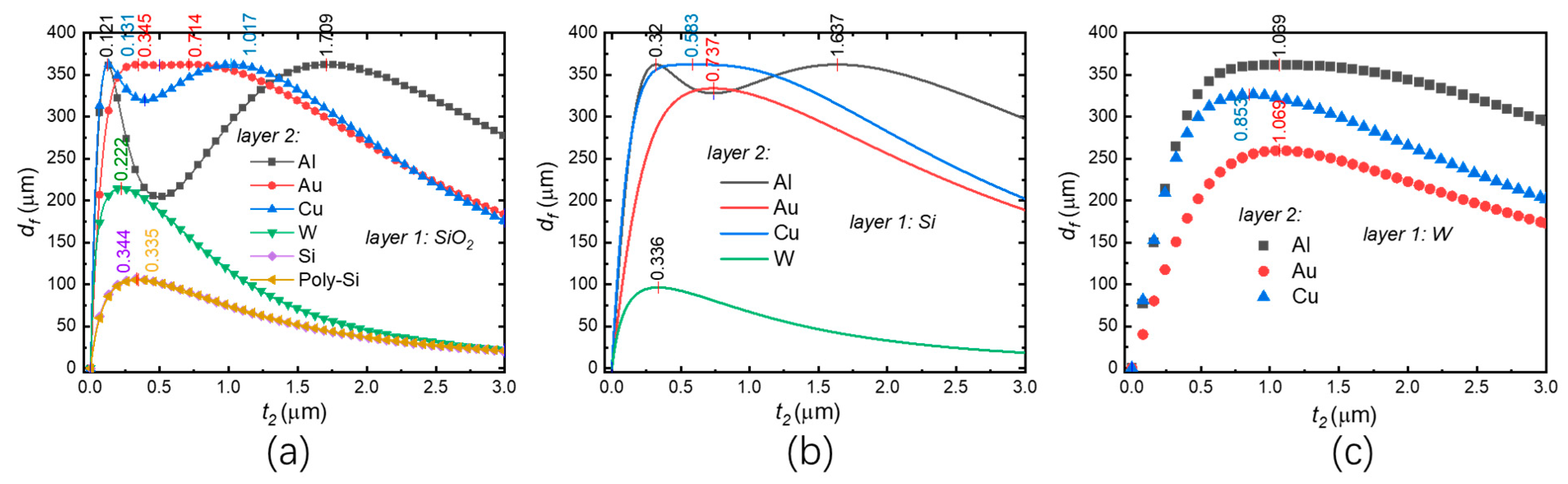
3.1.2. Bi-Material Solid Thermal Actuators
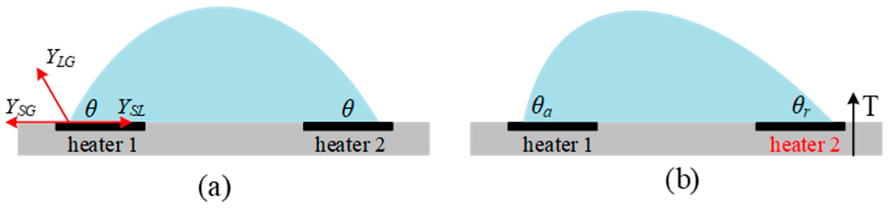
3.2. Liquid-Based Thermal Actuators
3.3. Thermo-Pneumatic Actuation
4. Electrothermal Micromirrors
4.1. Solid-State Thermal Micromirrors
4.1.1. Single-Material Solid-State Thermal Micromirrors
U Shaped Thermal Actuator-Based Micromirrors
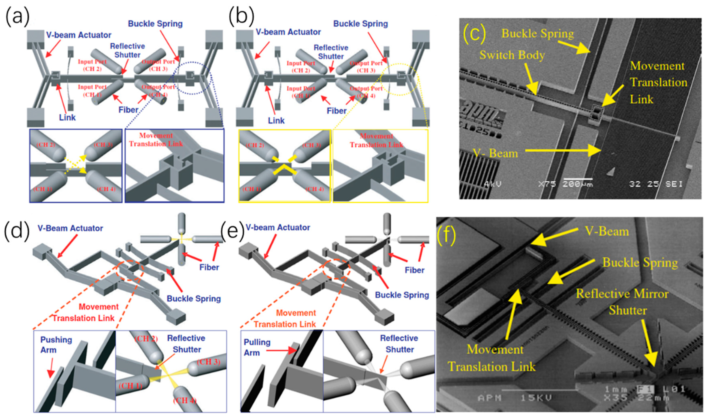
V-Shaped Thermal Actuator-Based Micromirrors
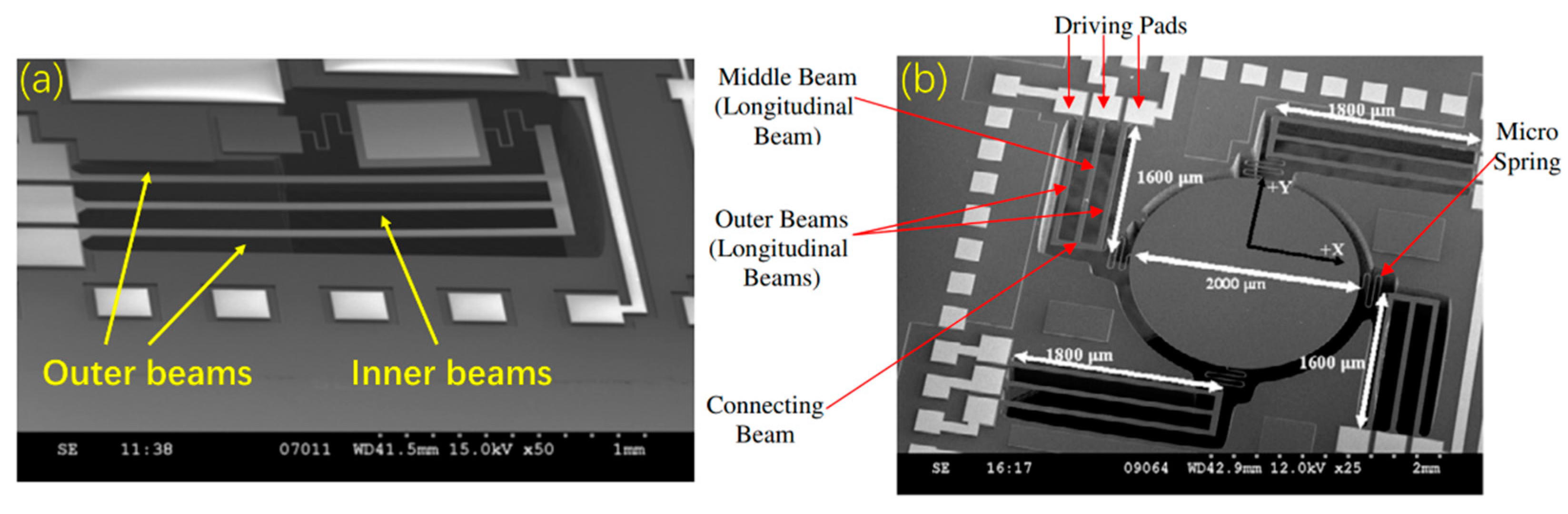
Buckle-Beam Thermal Actuator-Based Micromirrors
Three-Beam Thermal Actuator-Based Micromirrors
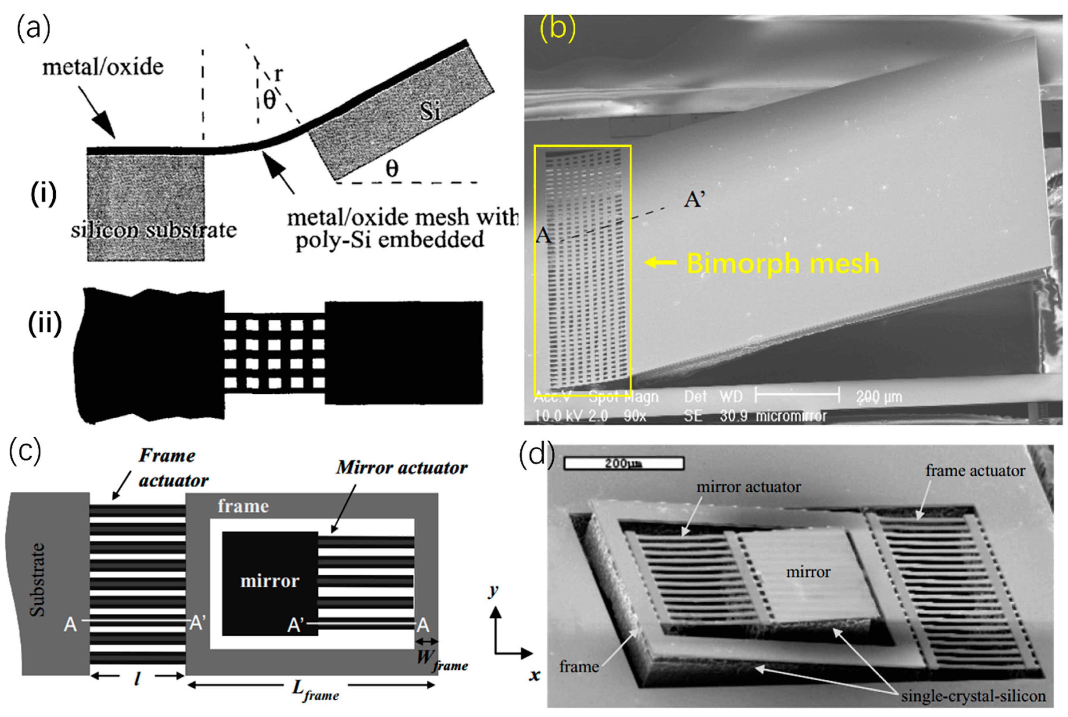
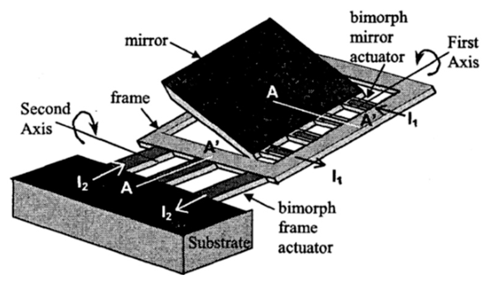
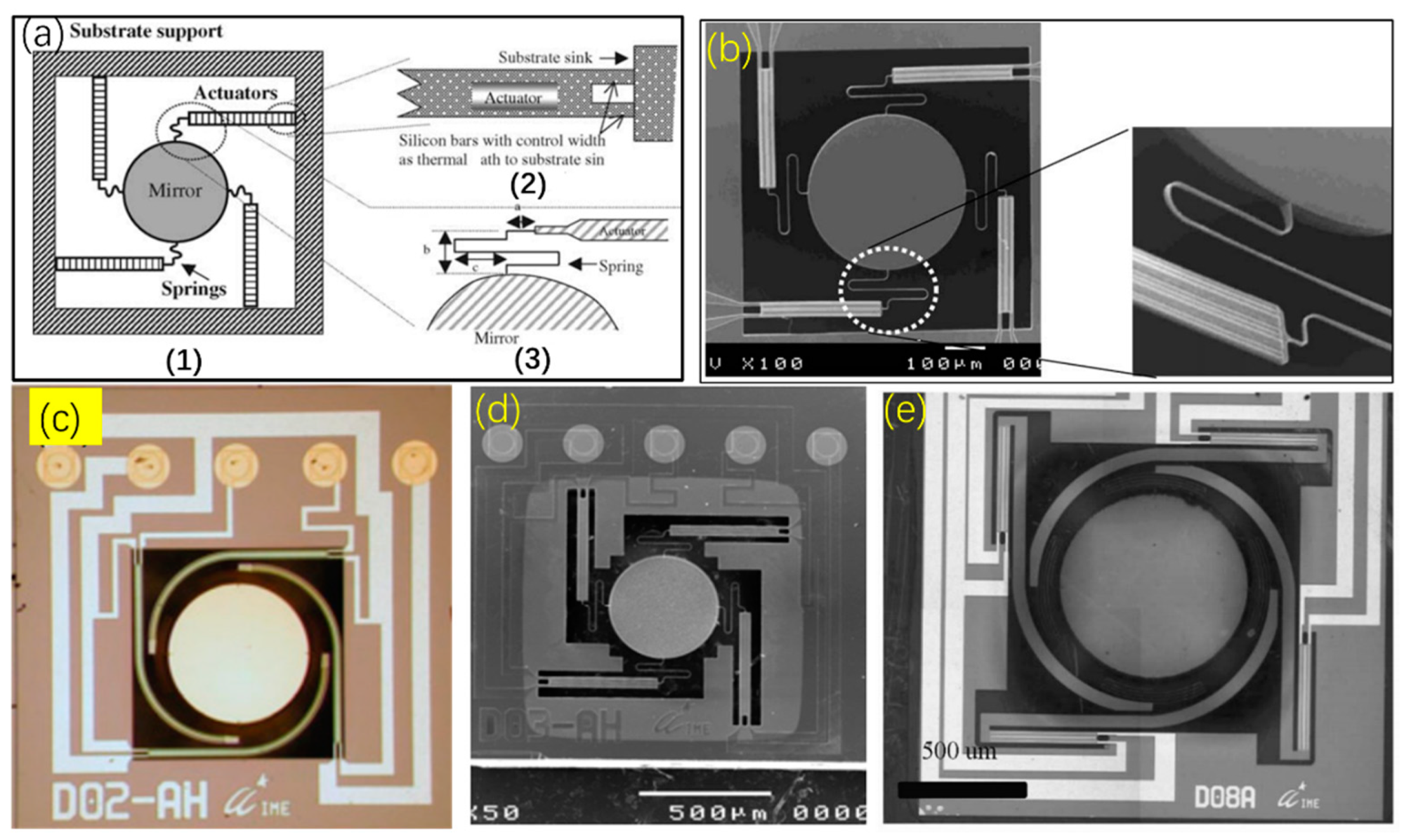
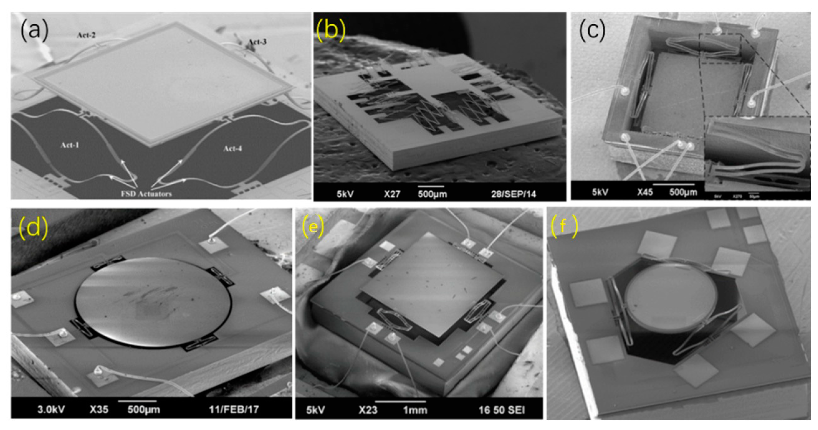
4.1.2. Bi-Material Solid Thermal Micromirror
Single Bimorph Thermal Micromirrors
Triple Bimorphs Thermal Micromirrors
Quadruple Bimorphs Thermal Micromirrors
An Origami Inspired Bimorph Thermal Micromirror
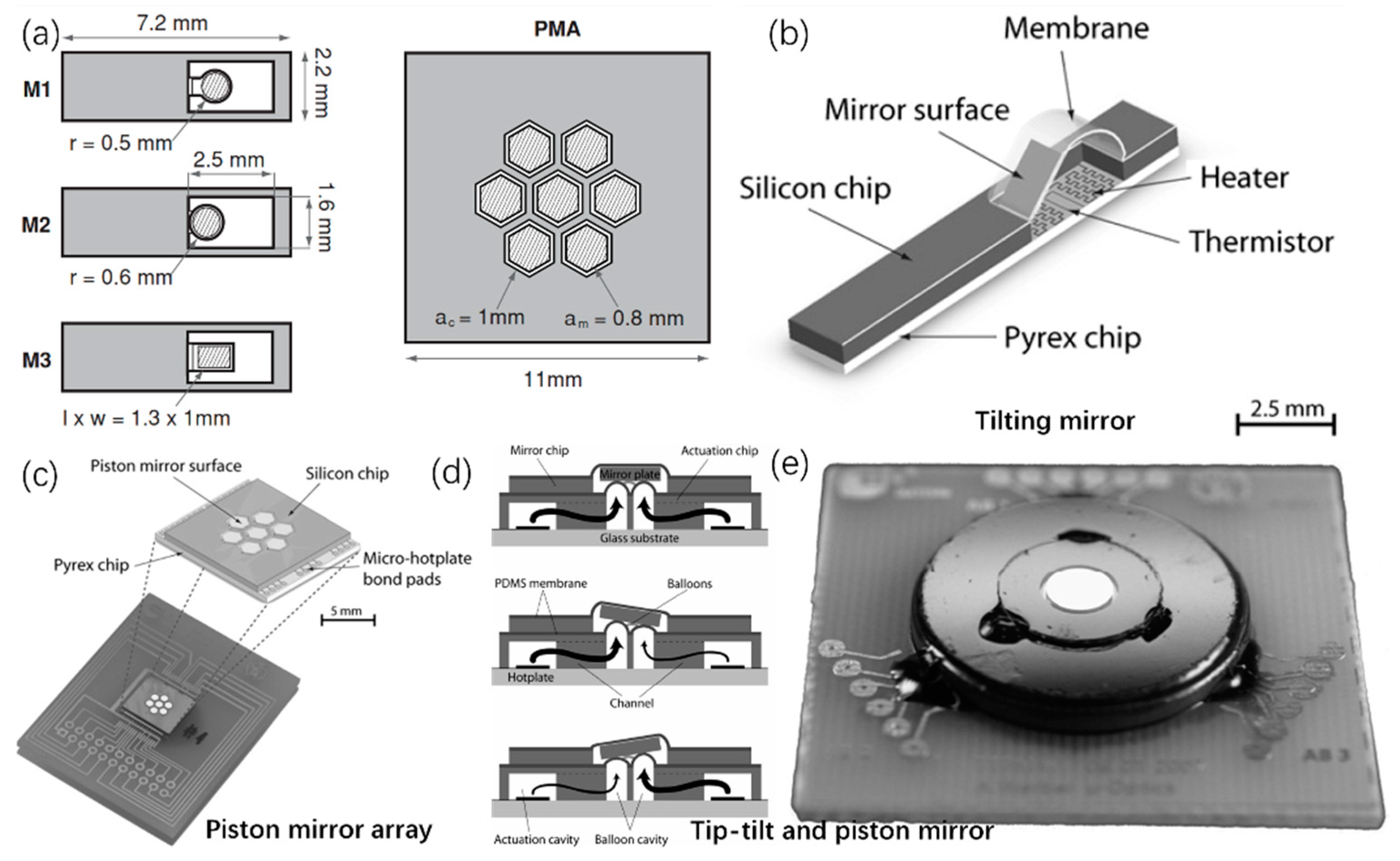
4.2. Liquid-Based Thermal Micromirrors
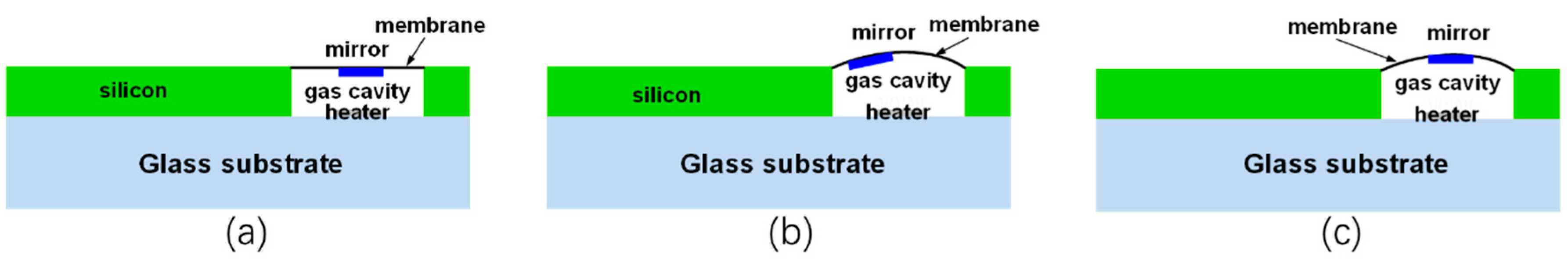
4.3. Thrmo-Pneumatic Micromirrors
4.4. Electrothermal Actuator-Base Hybrid Micromirrors
4.5. Summary
5. Conclusions and Future Perspectives
Author Contributions
Funding
Institutional Review Board Statement
Informed Consent Statement
Conflicts of Interest
References
- Sakai, S.; Ueno, K.; Ishizuka, T.; Yawo, H. Parallel and patterned optogenetic manipulation of neurons in the brain slice using a DMD-based projector. Neurosci. Res. 2013, 75, 59–64. [Google Scholar] [CrossRef] [PubMed]
- Shan, X.C.; Ikehara, T.; Murakoshi, Y.; Maeda, R. Applications of micro hot embossing for optical switch formation. Sens. Actuators A Phys. 2005, 119, 433–440. [Google Scholar] [CrossRef]
- Smith, B.; Hellman, B.; Gin, A.; Espinoza, A.; Takashima, Y. Single chip lidar with discrete beam steering by digital micromirror device. Opt. Express 2017, 25, 14732–14745. [Google Scholar] [CrossRef] [PubMed]
- Kaylor, B.M.; Keith, C.J.; Roos, P.A.; Reibel, R.R. Face recognition via a projective compressive sensing system. In Proceedings of the Emerging Digital Micromirror Device Based Systems and Applications IV, San Francisco, CA, USA, 21–26 January 2012; SPIE: Bellingham, WA, USA, 2012; Volume 8254, pp. 118–123. [Google Scholar]
- Xie, H.; Jain, A.; Xie, T.; Pan, Y.; Fedder, G.K. A single-crystal silicon-based micromirror with large scanning angle for biomedical applications. In Proceedings of the Conference on Lasers and Electro-Optics, Baltimore, MD, USA, 1–6 June 2003; Optical Society of America: Washington, DC, USA, 2003; p. CTuW1. [Google Scholar]
- MacKenty, J.W.; Greenhouse, M.A.; Green, R.F.; Sparr, L.; Ohl, R.G., IV; Winsor, R.S. IRMOS: An infrared multi-object spectrometer using a MEMs micromirror array. In Proceedings of the Instrument Design and Performance for Optical/Infrared Ground-Based Telescopes, Waikoloa, HI, USA, 7 March 2003; International Society for Optics and Photonics: Bellingham, WA, USA, 2003; Volume 4841, pp. 953–961. [Google Scholar]
- Kang, S.-Y.; Park, J.-H.; Ji, C.-H. Design optimization of a 6.4 mm-diameter electromagnetic 2D scanning micromirror. Opt. Express 2020, 28, 31272–31286. [Google Scholar] [PubMed]
- Fan, Y.; Cui, C.; Yu, H.; Shen, W.; Wang, Z.; Li, J. An electrostatic vertical comb-drive micromirror with self-aligned assembly. In Proceedings of the 2017 IEEE 12th International Conference on Nano/Micro Engineered and Molecular Systems (NEMS), Los Angeles, CA, USA, 9–12 April 2017; pp. 268–272. [Google Scholar]
- Sadhukhan, D.; Singh, G.P. Study of electrostatic actuated MEMS biaxial scanning micro-mirror with comb structure. In AIP Conference Proceedings; AIP Publishing LLC: Melville, NY, USA, 2020; Volume 2269, p. 030019. [Google Scholar]
- Liu, W.; Zhu, Y.; Li, J.; Virendrapal, A.S.; Tang, Y.; Wang, B.; Xie, H. Two-axis scanning micromirror based on a tilt-and-lateral shift-free piezoelectric actuator. In Proceedings of the SENSORS, Waikoloa, HI, USA, 1–4 November 2010; pp. 2189–2192. [Google Scholar]
- Shao, J.; Li, Q.; Feng, C.; Li, W.; Yu, H. AlN based piezoelectric micromirror. Opt. Lett. 2018, 43, 987–990. [Google Scholar] [CrossRef] [PubMed]
- Girbau, D.; Llamas, M.A.; Casals-Terré, J.; Simó-Selvas, X.; Pradell, L.; Lázaro, A. A low-power-consumption out-of-plane electrothermal actuator. J. Microelectromech. Syst. 2007, 16, 719–727. [Google Scholar] [CrossRef] [Green Version]
- Thangavel, A.; Rengaswamy, R.; Sukumar, P.K.; Sekar, R. Modelling of Chevron electrothermal actuator and its performance analysis. Microsyst. Technol. 2018, 24, 1767–1774. [Google Scholar] [CrossRef]
- Varona, J.; Tecpoyotl-Torres, M.; Hamoui, A.A. Design of MEMS vertical–horizontal chevron thermal actuators. Sens. Actuators A Phys. 2009, 153, 127–130. [Google Scholar] [CrossRef]
- Yan, D.; Khajepour, A.; Mansour, R. Design and modeling of a MEMS bidirectional vertical thermal actuator. J. Micromech. Microeng. 2004, 14, 841. [Google Scholar] [CrossRef]
- Knick, C.R.; Sharar, D.J.; Wilson, A.A.; Smith, G.L.; Morris, C.J.; Bruck, H.A. High frequency, low power, electrically actuated shape memory alloy MEMS bimorph thermal actuators. J. Micromech. Microeng. 2019, 29, 075005. [Google Scholar] [CrossRef]
- Dhull, R.K.; Puchades, I.; Fuller, L.; Lu, Y.W. Optical micromirror actuation using thermocapillary effect in microdroplets. In Proceedings of the 2009 IEEE 22nd International Conference on Micro Electro Mechanical Systems, Sorrento, Italy, 25–29 January 2009; pp. 995–998. [Google Scholar]
- Werber, A.; Zappe, H. Thermo-pneumatically actuated, membrane-based micro-mirror devices. J. Micromech. Microeng. 2006, 16, 2524. [Google Scholar] [CrossRef]
- Brown, G.; Li, L.; Bauer, R.; Liu, J.; Uttamchandani, D. A two-axis hybrid MEMS scanner incorporating electrothermal and electrostatic actuators. In Proceedings of the 2010 International Conference on Optical MEMS and Nanophotonics, Sapporo, Japan, 9–12 August 2010. [Google Scholar]
- Koh, K.H.; Lee, C. A two-dimensional MEMS scanning mirror using hybrid actuation mechanisms with low operation voltage. J. Microelectromech. Syst. 2012, 21, 1124–1135. [Google Scholar] [CrossRef]
- Zhang, X.; Liu, L.; Liang, W.; Li, X.; Xie, H. An electrothermal/electrostatic dual driven MEMS scanner with large in-plane and out-of-plane displacement. In Proceedings of the 2013 International Conference on Optical MEMS and Nanophotonics (OMN), Kanazawa, Japan, 18–22 August 2013. [Google Scholar]
- Reid, J.R.; Bright, V.M.; Comtois, J.H. Force measurements of polysilicon thermal microactuators. In Proceedings of the Micromachined Devices and Components II, Austin, TX, USA, 14–15 October 1996; International Society for Optics and Photonics: Bellingham, WA, USA, 1996; Volume 2882, pp. 296–306. [Google Scholar]
- Butler, J.T.; Bright, V.M.; Reid, J.R. Scanning and rotating micromirrors using thermal actuators. In Proceedings of the Optical Scanning Systems: Design and Applications, San Diego, CA, USA, 27 July–1 August 1997; International Society for Optics and Photonics: Bellingham, WA, USA, 1997; Volume 3131, pp. 134–144. [Google Scholar]
- COMSOL Multiphysics. Available online: https://cn.comsol.com/ (accessed on 12 December 2021).
- Huang, Q.-A.; Lee, N.K.S. Analysis and design of polysilicon thermal flexure actuator. J. Micromech. Microeng. 1999, 9, 64. [Google Scholar] [CrossRef]
- Reid, J.R.; Bright, V.M.; Comtois, J.H. A surface micromachined rotating micro-mirror normal to the substrate. In Proceedings of the Digest IEEE/Leos 1996 Summer Topical Meeting. Advanced Applications of Lasers in Materials and Processing, Keystone, CO, USA, 5–9 August 1996; pp. 39–40. [Google Scholar]
- Gianchandani, Y.B.; Najafi, K. Bent-beam strain sensors. J. Microelectromech. Syst. 1996, 5, 52–58. [Google Scholar] [CrossRef]
- Cragun, R.; Howell, L.L. Linear thermomechanical microactuators. In Proceedings of the ASME International Mechanical Engineering Congress and Exposition, Nashville, NT, USA, 14–19 November 1999; American Society of Mechanical Engineers: New York, NY, USA, 1999; Volume 16387, pp. 181–188. [Google Scholar]
- Que, L.; Park, J.S.; Gianchandani, Y.B. Bent-beam electro-thermal actuators for high force applications. In Proceedings of the Technical Digest, IEEE International MEMS 99 Conference, Twelfth IEEE International Conference on Micro Electro Mechanical Systems (Cat. No. 99CH36291), Orlando, FL, USA, 21–21 January 1999; pp. 31–36. [Google Scholar]
- Baracu, A.; Voicu, R.; Müller, R.; Avram, A.; Pustan, M.; Chiorean, R.; Birleanu, C.; Dudescu, C. Design and fabrication of a MEMS chevron-type thermal actuator. In AIP Conference Proceedings, Proceedings of the NN14 and ISFOE14, Thessaloniki, Greece, 12 June 2014; American Institute of Physics: College Park, MD, USA, 2015; Volume 1646, pp. 25–30. [Google Scholar]
- Timoshenko, S. Analysis of bi-metal thermostats. JOSA 1925, 11, 233–255. [Google Scholar] [CrossRef]
- Riethmuller, W.; Wolfgang, B. Thermally excited silicon microactuators. IEEE Trans. Electron. Devices 1988, 35, 758–763. [Google Scholar] [CrossRef]
- Benecke, W.; Riethmuller, W. Applications of silicon microactuators based on bimorph structures. In Proceedings of the IEEE Micro Electro Mechanical Systems, ‘An Investigation of Micro Structures, Sensors, Actuators, Machines and Robots’, Salt Lake City, UT, USA, 20–22 February 1989; pp. 116–120. [Google Scholar]
- Peng, W.; Xiao, Z.; Farmer, K.R. Optimization of thermally actuated bimorph cantilevers for maximum deflection. Nanotech Proc. 2003, 1, 376–379. [Google Scholar]
- Xie, H.; Todd, S.; Jain, A.; Fedder, G.K. Single-crystal silicon based electrothermal MEMS mirrors for biomedical imaging applications. In MEMS/NEMS; Springer: Boston, MA, USA, 2006; pp. 1429–1471. [Google Scholar]
- Jain, A.; Xie, T.; Pan, Y.; Fedder, G.K.; Xie, H. A two-axis electrothermal SCS micromirror for biomedical imaging. In Proceedings of the 2003 IEEE/LEOS International Conference on Optical MEMS (Cat. No. 03EX682), Waikoloa, HI, USA, 18–21 August 2003; pp. 14–15. [Google Scholar]
- Todd, S.T.; Jain, A.; Qu, H.; Xie, H. A 3-D micromirror utilizing inverted-series-connected electrothermal bimorph actuators for piston and tilt motion. In Proceedings of the IEEE/LEOS International Conference on Optical MEMS and Their Applications Conference, Oulu, Finland, 1–4 August 2005; pp. 27–28. [Google Scholar]
- Wu, L.; Xie, H. A lateral-shift-free and large-vertical-displacement electrothermal actuator for scanning micromirror/lens. In Proceedings of the TRANSDUCERS 2007—2007 International Solid-State Sensors, Actuators and Microsystems Conference, Lyon, France, 10–14 June 2007; pp. 1075–1078. [Google Scholar]
- Fyen, W.; Holsteyns, F.; Bearda, T.; Arnauts, S.; Van Steenbergen, J.; Doumen, G.; Kenis, K.; Mertens, P.W. A Detailed Study of Semiconductor Wafer Drying. In Developments in Surface Contamination and Cleaning; William Andrew Publishing: Norwich, NY, USA, 2008; pp. 1067–1136. [Google Scholar]
- Berthier, J. Micro-Drops and Digital Microfluidics; William Andrew: Norwich, NY, USA, 2012. [Google Scholar]
- Reid, J.R.; Bright, V.M.; Comtois, J.H. Arrays of thermal microactuators coupled to micro-optical components. In Proceedings of the Actuator Technology and Applications, Denver, CO, USA, 4–9 August 1996; SPIE: Bellingham, WA, USA, 1996; Volume 2865, pp. 74–82. [Google Scholar]
- Markus, K.W.; Koester, D.A. Multi-User MEMS Process (MUMPs) Introduction and Design Rules; MCNC Electronic Technologies Division: Research Triangle, NC, USA, 1994. [Google Scholar]
- Reid, J.R.; Bright, V.M.; Butler, J.T. Automated assembly of flip-up micromirrors. Sens. Actuators A Phys. 1998, 66, 292–298. [Google Scholar] [CrossRef]
- Comtois, J.H. Surface micromachined polysilicon thermal actuator arrays and applications. In Proceedings of the Technical Digest, Solid State Sensor and Actuator Workshop, Hilton Head Island, SC, USA, 3–6 June 1996; pp. 174–177. [Google Scholar]
- Chen, W.C.; Wu, C.Y.; Lee, C. Bi-directional movable latching structure using electrothermal V-beam actuators for optical switch application. In Proceedings of the 2003 IEEE/LEOS International Conference on Optical MEMS (Cat. No. 03EX682), Waikoloa, HI, USA, 18–21 August 2003; pp. 149–150. [Google Scholar]
- Lee, C.; Wu, C.Y. Study of electrothermal V-beam actuators and latched mechanism for optical switch. J. Micromech. Microeng. 2004, 15, 11. [Google Scholar] [CrossRef]
- Eun, Y.; Kim, J. Thermally driven torsional micromirrors using pre-bent torsion bar for large static angular displacement. J. Micromech. Microeng. 2009, 19, 045009. [Google Scholar] [CrossRef]
- Sinclair, M. 1D and 2D scanning mirrors using thermal buckle-beam actuation. In Proceedings of the Device and Process Technologies for MEMS and Microelectronics II, Adelaide, Australia, 17–19 December 2001; SPIE: Bellingham, WA, USA, 2001; Volume 4592, pp. 307–314. [Google Scholar]
- Sinclair, M. A high frequency resonant scanner using thermal actuation. In Proceedings of the Technical Digest. MEMS 2002 IEEE International Conference, Fifteenth IEEE International Conference on Micro Electro Mechanical Systems (Cat. No. 02CH37266), Las Vegas, NV, USA, 24–24 January 2002; pp. 698–701. [Google Scholar]
- Li, L.; Begbie, M.; Brown, G.; Uttamchandani, D. Design, simulation and characterization of a MEMS optical scanner. J. Micromech. Microeng. 2007, 17, 1781. [Google Scholar] [CrossRef]
- Li, L.; Stewart, G.; Thursby, G.; Arsad, N.; Uttamchandani, D.; Culshaw, B.; Wang, Y. External laser intensity modulation based on a MEMS micro-mirror for photo-acoustic gas sensing. In Proceedings of the 5th International Symposium on Advanced Optical Manufacturing and Testing Technologies: Design, Manufacturing, and Testing of Micro-and Nano-Optical Devices and Systems, Dalian, China, 26–29 April 2010; International Society for Optics and Photonics: Bellingham, WA, USA, 2010; Volume 7657, p. 76570M. [Google Scholar]
- Li, L.; Stankovic, V.; Stankovic, L.; Li, L.; Cheng, S.; Uttamchandani, D. Single pixel optical imaging using a scanning MEMS mirror. J. Micromech. Microeng. 2011, 21, 025022. [Google Scholar] [CrossRef]
- Schweizer, S.; Calmes, S.; Laudon, M.; Renaud, P. Thermally actuated optical microscanner with large angle and low consumption. Sens. Actuators A Phys. 1999, 76, 470–477. [Google Scholar] [CrossRef]
- Buser, R.A.; De Rooij, N.F.; Tischhauser, H.; Dommann, A.; Staufert, G. Biaxial scanning mirror activated by bimorph structures for medical applications. Sens. Actuators A Phys. 1992, 31, 29–34. [Google Scholar] [CrossRef]
- Bühler, J.; Funk, J.; Paul, O.; Steiner, F.P.; Baltes, H. Thermally actuated CMOS micromirrors. Sens. Actuators A Phys. 1995, 47, 572–575. [Google Scholar] [CrossRef]
- Funk, J.; Korvink, J.G.; Bachtold, M.; Buhler, J.; Baltes, H. Coupled 3D thermo-electro-mechanical simulations of microactuators. In Proceedings of the Ninth International Workshop on Micro Electromechanical Systems, San Diego, CA, USA, 11–15 February 1996; pp. 133–138. [Google Scholar]
- Xie, H.; Pan, Y.; Fedder, G.K. A SCS CMOS micromirror for optical coherence tomographic imaging. In Proceedings of the Technical Digest. MEMS 2002 IEEE International Conference. Fifteenth IEEE International Conference on Micro Electro Mechanical Systems (Cat. No. 02CH37266), Las Vegas, NV, USA, 24 January 2002; pp. 495–498. [Google Scholar]
- Jain, A.; Qu, H.; Todd, S.; Fedder, G.K.; Xie, H. Electrothermal SCS micromirror with large-vertical-displacement actuation. In Proceedings of the 2004 Solid State Sensor, Actuator and Microsystems Workshop, Hilton Head Island, SC, USA, 6–10 June 2004; pp. 228–231. [Google Scholar]
- Lee, A.P.; McConaghy, C.F.; Sommargren, G.; Krulevitch, P.; Campbell, E.W. Vertical-actuated electrostatic comb drive with in situ capacitive position correction for application in phase shifting diffraction interferometry. J. Microelectromech. Syst. 2003, 12, 960–971. [Google Scholar] [CrossRef]
- Jain, A.; Kopa, A.; Pan, Y.; Fedder, G.K.; Xie, H. A two-axis electrothermal micromirror for endoscopic optical coherence tomography. IEEE J. Sel. Top. Quantum Electron. 2004, 10, 636–642. [Google Scholar] [CrossRef]
- Singh, J.; Gan, T.; Agarwal, A.; Liw, S. 3D free space thermally actuated micromirror device. Sens. Actuators A Phys. 2005, 123, 468–475. [Google Scholar] [CrossRef]
- Xu, Y.; Singh, J.; Jason, T.H.S.; Ramakrishna, K.; Premchandran, C.S.; Kelvin, C.W.S.; Kuan, C.T.; Chen, N.; Olivo, M.C.; Sheppard, C.J.R. MEMS based non-rotatory circumferential scanning optical probe for endoscopic optical coherence tomography. In Proceedings of the European Conference on Biomedical Optics, Munich, Germany, 17–21 June 2007; Optical Society of America: Washington, DC, USA, 2007; p. 6627_33. [Google Scholar]
- Xu, Y.; Singh, J.; Premachandran, C.S.; Khairyanto, A.; Chen, K.W.S.; Chen, N.; Sheppard, C.J.R.; Olivo, M. Design and development of a 3D scanning MEMS OCT probe using a novel SiOB package assembly. J. Micromech. Microeng. 2008, 18, 125005. [Google Scholar] [CrossRef]
- Singh, J.; Teo, J.H.S.; Xu, Y.; Premachandran, C.S.; Chen, N.; Kotlanka, R.; Olivo, M.; Sheppard, C.J.R. A two axes scanning SOI MEMS micromirror for endoscopic bioimaging. J. Micromech. Microeng. 2007, 18, 025001. [Google Scholar] [CrossRef]
- Xu, Y.; Singh, J.; Selvaratnam, T.; Chen, N. Two-axis gimbal-less electrothermal micromirror for large-angle circumferential scanning. IEEE J. Sel. Top. Quantum Electron. 2009, 15, 1432–1438. [Google Scholar]
- Wu, L.; Xie, H. A large vertical displacement electrothermal bimorph microactuator with very small lateral shift. Sens. Actuators A Phys. 2008, 145, 371–379. [Google Scholar] [CrossRef]
- Liu, L.; Sun, J.; Lin, E.; Xie, H.; Wu, L. Miniature endoscopic optical coherence tomography probe employing a two-axis microelectromechanical scanning mirror with through-silicon vias. J. Biomed. Opt. 2011, 16, 026006. [Google Scholar] [CrossRef] [PubMed]
- Liu, L.; Xie, H. Three-dimensional confocal scanning microscope using an MEMS mirror for lateral scan and an MEMS lens scanner for depth scan. In Proceedings of the 2012 International Conference on Optical MEMS and Nanophotonics, Banff, AB, Canada, 6–9 August 2012; pp. 158–159. [Google Scholar]
- Zhang, X.; Zhou, L.; Xie, H. A fast, large-stroke electrothermal MEMS mirror based on Cu/W bimorph. Micromachines 2015, 6, 1876–1889. [Google Scholar] [CrossRef]
- Liu, L.; Pal, S.; Xie, H. MEMS mirrors based on curved concentric electrothermal actuators with very small lateral shift and tilt. In Proceedings of the 2011 16th International Solid-State Sensors, Actuators and Microsystems Conference, Beijing, China, 5–9 June 2011; pp. 2522–2525. [Google Scholar]
- Liu, L.; Pal, S.; Xie, H. MEMS mirrors based on a curved concentric electrothermal actuator. Sens. Actuators A Phys. 2012, 188, 349–358. [Google Scholar] [CrossRef]
- Ervin, J.D.; Brei, D. Recurve piezoelectric-strain-amplifying actuator architecture. IEEE/ASME Trans. Mechatron. 1998, 3, 293–301. [Google Scholar] [CrossRef]
- Oz, A.; Fedder, G.K. CMOS electro-thermal lateral micromovers for actuation and self-assembly. In Proceedings of the SEM Annual Conference on Experimental and Applied Mechanics, Charlotte, NC, USA, 2–4 June 2003; pp. 2–4. [Google Scholar]
- Jia, K.; Pal, S.; Xie, H. An electrothermal tip–tilt–piston micromirror based on folded dual S-shaped bimorphs. J. Microelectromech. Syst. 2009, 18, 1004–1015. [Google Scholar]
- Wang, W.; Samuelson, S.R.; Chen, J.; Xie, H. Miniaturizing Fourier transform spectrometer with an electrothermal micromirror. IEEE Photonics Technol. Lett. 2015, 27, 1418–1421. [Google Scholar] [CrossRef]
- Xie, H.; Lan, S.; Wang, D.; Wang, W.; Sun, J.; Liu, H.; Cheng, J.; Ding, J.; Qin, Z.; Chen, Q.; et al. Miniature fourier transform spectrometers based on electrothermal MEMS mirrors with large piston scan range. In Proceedings of the 2015 IEEE SENSORS, Busan, Korea, 1–4 November 2015; pp. 1–4. [Google Scholar]
- Wang, D.; Strassle, S.; Stainsby, A.; Bai, Y.; Koppal, S.; Xie, H. A compact 3D lidar based on an electrothermal two-axis MEMS scanner for small UAV. In Proceedings of the Laser Radar Technology and Applications XXIII, Orlando, FL, USA, 15–19 April 2018; International Society for Optics and Photonics: Bellingham, WA, USA, 2018; Volume 10636, p. 106360G. [Google Scholar]
- Wang, D.; Watkins, C.; Aradhya, M.; Koppal, S.; Xie, H. A large aperture 2-axis electrothermal MEMS mirror for compact 3D LiDAR. In Proceedings of the 2019 International Conference on Optical MEMS and Nanophotonics (OMN), Daejeon, Korea, 28 July–1 August 2019; pp. 180–181. [Google Scholar]
- Wang, D.; Watkins, C.; Koppal, S.; Li, M.; Ding, Y.; Xie, H. A compact omnidirectional laser scanner based on an electrothermal tripod mems mirror for lidar. In Proceedings of the 2019 20th International Conference on Solid-State Sensors, Actuators and Microsystems & Eurosensors XXXIII (TRANSDUCERS & EUROSENSORS XXXIII), Berlin, Germany, 23–27 June 2019; pp. 1526–1529. [Google Scholar]
- Zhang, X.; Li, B.; Li, X.; Xie, H. A robust, fast electrothermal micromirror with symmetric bimorph actuators made of copper/tungsten. In Proceedings of the 2015 Transducers—2015 18th International Conference on Solid-State Sensors, Actuators and Microsystems (TRANSDUCERS), Berlin, Germany, 23–27 June 2019; pp. 912–915. [Google Scholar]
- Wang, D.; Zhang, X.; Zhou, L.; Liang, M.; Zhang, D.; Xie, H. An ultra-fast electrothermal micromirror with bimorph actuators made of copper/tungsten. In Proceedings of the 2017 International Conference on Optical MEMS and Nanophotonics (OMN), Santa Fe, NM, USA, 13–17 August 2017; pp. 1–2. [Google Scholar]
- Zhou, L.; Zhang, X.; Xie, H. An electrothermal Cu/W bimorph tip-tilt-piston MEMS mirror with high reliability. Micromachines 2019, 10, 323. [Google Scholar] [CrossRef] [Green Version]
- Tanguy, Q.A.; Duan, C.; Wang, W.; Xie, H.; Bargiel, S.; Struk, P.; Lutz, P.; Gorecki, C. A 2-axis electrothermal MEMS micro-scanner with torsional beam. In Proceedings of the 2016 International Conference on Optical MEMS and Nanophotonics (OMN), Singapore, 31 July–4 August 2016; pp. 1–2. [Google Scholar]
- Tanguy, Q.A.; Bargiel, S.; Xie, H.; Passilly, N.; Barthès, M.; Gaiffe, O.; Rutkowski, J.; Lutz, P.; Gorecki, C. Design and fabrication of a 2-axis electrothermal mems micro-scanner for optical coherence tomography. Micromachines 2017, 8, 146. [Google Scholar] [CrossRef]
- Hashimoto, M.; Taguchi, Y. Design and fabrication of a kirigami-inspired electrothermal mems scanner with large displacement. Micromachines 2020, 11, 362. [Google Scholar] [CrossRef] [PubMed] [Green Version]
- Dhull, R.K. A Two Degrees-of-Freedom (DOF) Scanning Micromirror Using Thermocapillary Effect in Microdroplets; Rochester Institute of Technology: Rochester, NY, USA, 2010. [Google Scholar]
- Werber, A.; Zappe, H. Tunable pneumatic microoptics. J. Microelectromech. Syst. 2008, 17, 1218–1227. [Google Scholar] [CrossRef]
- Werber, A.; Zappe, H. A thermo-pneumatically actuated tip-tilt-piston mirror. In Proceedings of the TRANSDUCERS 2007—2007 International Solid-State Sensors, Actuators and Microsystems Conference, Lyon, France, 10–14 June 2007; pp. 1525–1528. [Google Scholar]
- Li, L.; Bauer, R.; Brown, G.; Uttamchandani, D. A symmetric hybrid MEMS scanner with electrothermal and electrostatic actuators. In Proceedings of the 16th International Conference on Optical MEMS and Nanophotonics, Istanbul, Turkey, 8–11 August 2011; pp. 163–164. [Google Scholar]
- Zhang, X.; Zhou, L.; Xie, H. A large range micro-XZ-stage with monolithic integration of electrothermal bimorph actuators and electrostatic comb drives. In Proceedings of the 2016 IEEE 29th International Conference on Micro Electro Mechanical Systems (MEMS), Shanghai, China, 24–28 January 2016; pp. 71–74. [Google Scholar]
- Eun, Y.; Na, H.; Choi, J.; Lee, J.I.; Kim, J. Angular vertical comb actuators assembled on-chip using in-plane electrothermal actuators and latching mechanisms. Sens. Actuators A Phys. 2011, 165, 94–100. [Google Scholar] [CrossRef]
- Lee, F.Y.; Zhou, X.; Fang, W.; Chen, S.C. Design of a tunable resonant micromirror. Sens. Actuators A Phys. 2015, 234, 72–81. [Google Scholar] [CrossRef]


| Layer 1 | Layer 2 | Optimal Thickness Ratio | ||||||
|---|---|---|---|---|---|---|---|---|
| Material-1 | E1 (GPa) | a1 (10−6K−1) | Melting (°C) | Material-2 | E2 (GPa) | a2 (10−6K−1) | Melting (°C) | |
| SiO2 | 70 | 0.5 | 1710 | Al | 70 | 23.1 | 660 | 0.12, 1.7 |
| Au | 70 | 14.2 | 1060 | 0.35–0.7 | ||||
| Cu | 120 | 16.5 | 0.13, 1 | |||||
| W | 411 | 4.5 | 3370 | 0.22 | ||||
| Si | 170 | 2.6 | 1410 | 0.344 | ||||
| Poly-Si | 160 | 2.6 | 1410 | 0.335 | ||||
| Si | 170 | 2.6 | 1410 | Al | 70 | 23.1 | -- | 0.32, 1.6 |
| Au | 70 | 14.2 | -- | 0.58 | ||||
| Cu | 120 | 16.5 | -- | 0.74 | ||||
| W | 411 | 4.5 | -- | 0.336 | ||||
| W | 411 | 4.5 | 3370 | Al | 70 | 23.1 | -- | 1.1 |
| Au | 70 | 14.2 | -- | 0.85 | ||||
| Cu | 120 | 16.5 | -- | 1.1 | ||||
| Principles of Micromirrors | Stroke (μm or °) | Voltage (V) | Types | Materials | Advantages | Disadvantages | References | |
|---|---|---|---|---|---|---|---|---|
| U-shaped | 15° | 9 V | 1D | Poly- Si | Low voltage | Complicated | [41] | |
| 360°-rotation | -- | Rotatory | Poly- Si | Rotatory | [44] | |||
| V-shaped | 6.5° | 13 V | 1D | Si | Reliability; Robustness | Low fill factor; Low stroke | [47] | |
| 5.4° 5.2° | 11 V | 2D | Si | [47] | ||||
| Buckle beams | 18° | 9 kHz | 1D | Poly- Si | Easy to fabrication | Low fill factor | [48] | |
| 20° | 16 kHz | 2D | Poly- Si | [49] | ||||
| Three beams | 10° | 18 V 2.19 kHz | TTP | Si | Innovation | Low stroke | [50,51] | |
| bimorph | suspend | 0.3° | -- | 1D | SiO2/Al | Innovation | Low stroke | [55] |
| 90° | -- | 1D | metal/SiO2 | Large stoke | High power consumption | [53] | ||
| With gimbal | 45°, 25° | 15 V 17 V | 2D | SiO2/Al | Large stroke; Low voltage injection | With gimble | [36] | |
| 200 μm | 6 V | TTP | SiO2/Al | [58] | ||||
| Origami-like | 200 μm | 25 V | Phase-only | NiCr/SiN | Innovation; Large stroke | Piston only | [85] | |
| ISC | 480 μm ±30° | 8 V | TTP | SiO2/Al | Large stroke; Low voltage injection; Lateral shift free | High power consumption | [74] | |
| 300 μm | 7 Vpp | SiO2/Al | [76] | |||||
| ±2.8° | SiO2/Al | [77] | ||||||
| 169 μm | 2.3 V | Cu/W | [80] | |||||
| 32°, 22° | -- | SiO2/Al | [83,84] | |||||
| LSF | 620 μm | 5.3 V | SiO2/Al | Large stoke; Very low voltage; Lateral shift free | High power consumption | [38,66] | ||
| ±15° | 3.6 V | SiO2/Al | [67] | |||||
| ±20° | 4.5 V | SiO2/Al | [68] | |||||
| 227 μm ±11° | 0.6 V 0.8 V | Al/W | [70] | |||||
| 200 μm | 0.9 V | Al/W | [71] | |||||
| 320 μm ±18° | 3 V | Cu/W | [69] | |||||
| Liquid droplet | 6.5° | 30 V | 1D | Oil | innovation | Vulnerable | [17] | |
| Thermal-pneumatic | 12.5° | 30 V | 1D | PDMS/gas cavity | Large stroke | High power consumption | [18] | |
| 80 μm | 20 V | Phase-only | ||||||
| 385 μm, 5° | 35 V | TTP | [88] | |||||
Publisher’s Note: MDPI stays neutral with regard to jurisdictional claims in published maps and institutional affiliations. |
© 2022 by the authors. Licensee MDPI, Basel, Switzerland. This article is an open access article distributed under the terms and conditions of the Creative Commons Attribution (CC BY) license (https://creativecommons.org/licenses/by/4.0/).
Share and Cite
Tang, Y.; Li, J.; Xu, L.; Lee, J.-B.; Xie, H. Review of Electrothermal Micromirrors. Micromachines 2022, 13, 429. https://doi.org/10.3390/mi13030429
Tang Y, Li J, Xu L, Lee J-B, Xie H. Review of Electrothermal Micromirrors. Micromachines. 2022; 13(3):429. https://doi.org/10.3390/mi13030429
Chicago/Turabian StyleTang, Yue, Jianhua Li, Lixin Xu, Jeong-Bong Lee, and Huikai Xie. 2022. "Review of Electrothermal Micromirrors" Micromachines 13, no. 3: 429. https://doi.org/10.3390/mi13030429