
Four-Port Dual-Band Multiple-Input Multiple-Output Dielectric Resonator Antenna for Sub-6 GHz 5G Communication Applications

Abstract
:1. Introduction
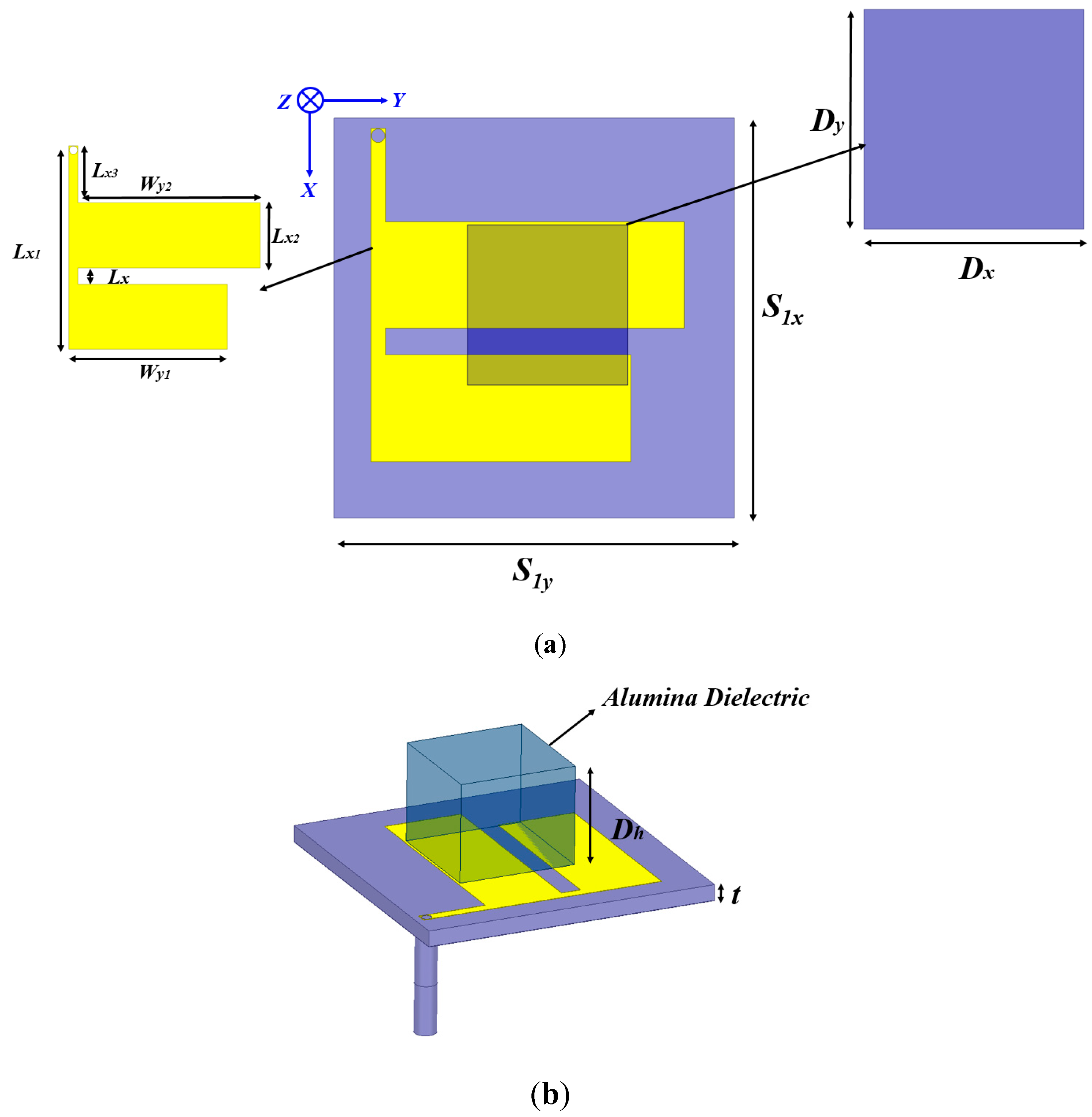
2. Antenna Design
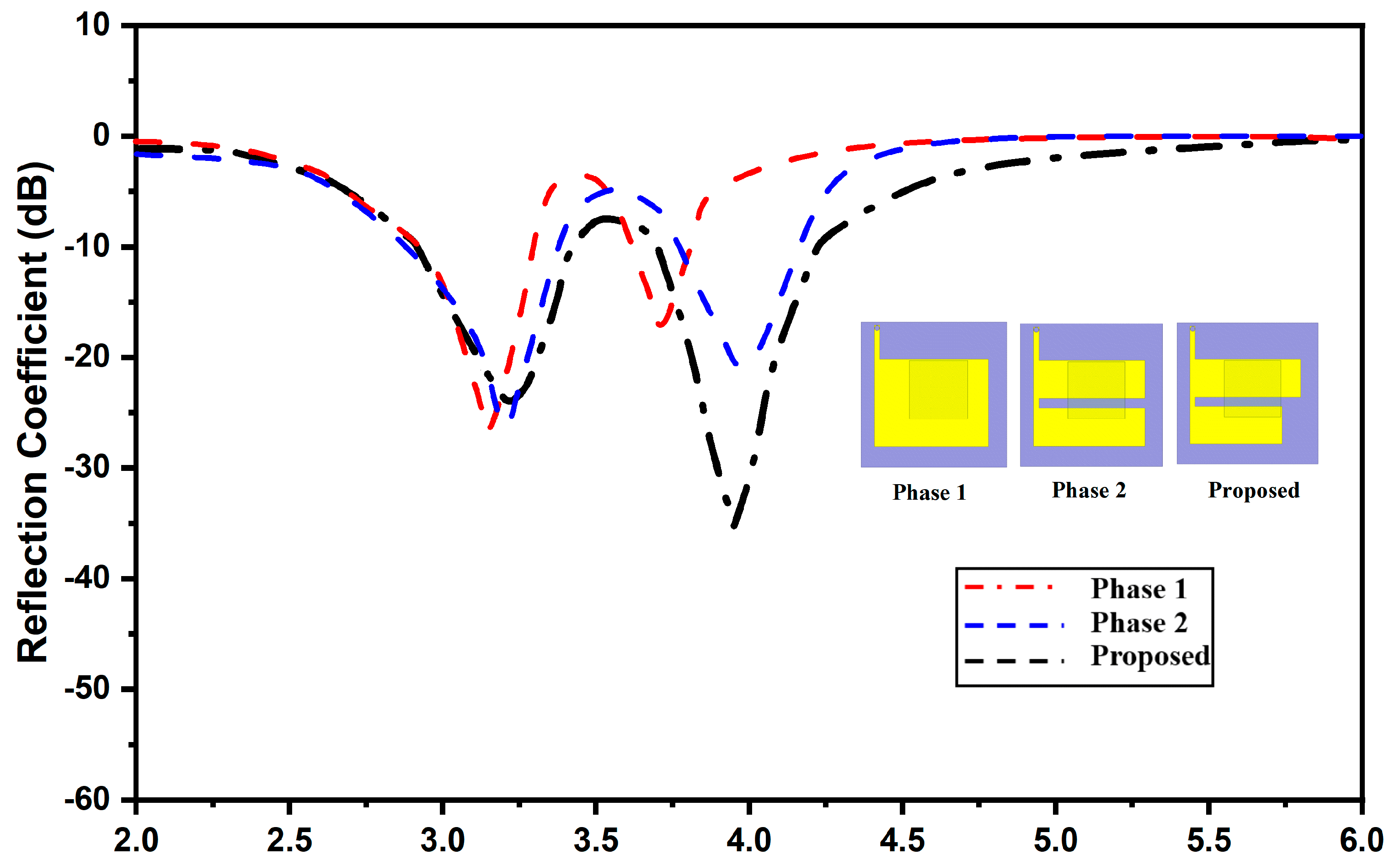
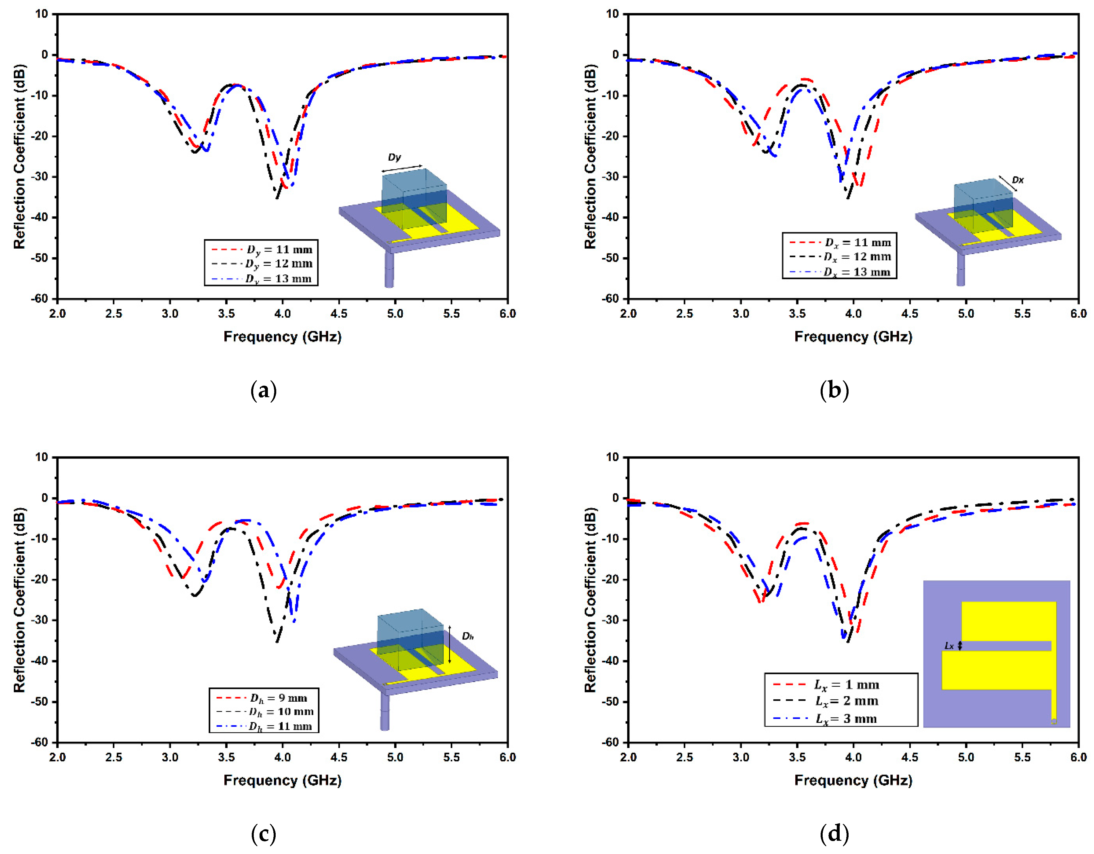
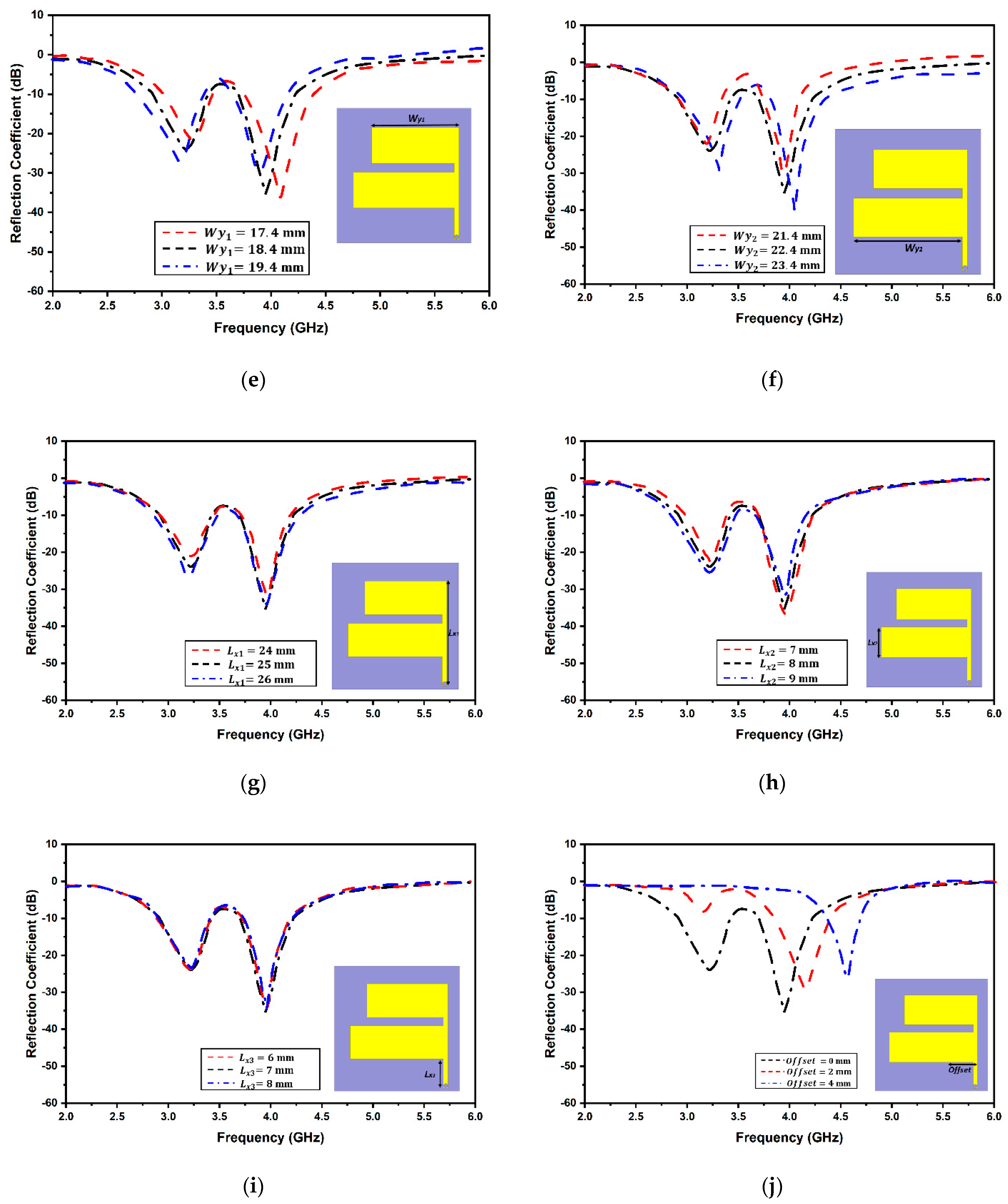
3. Design Optimization
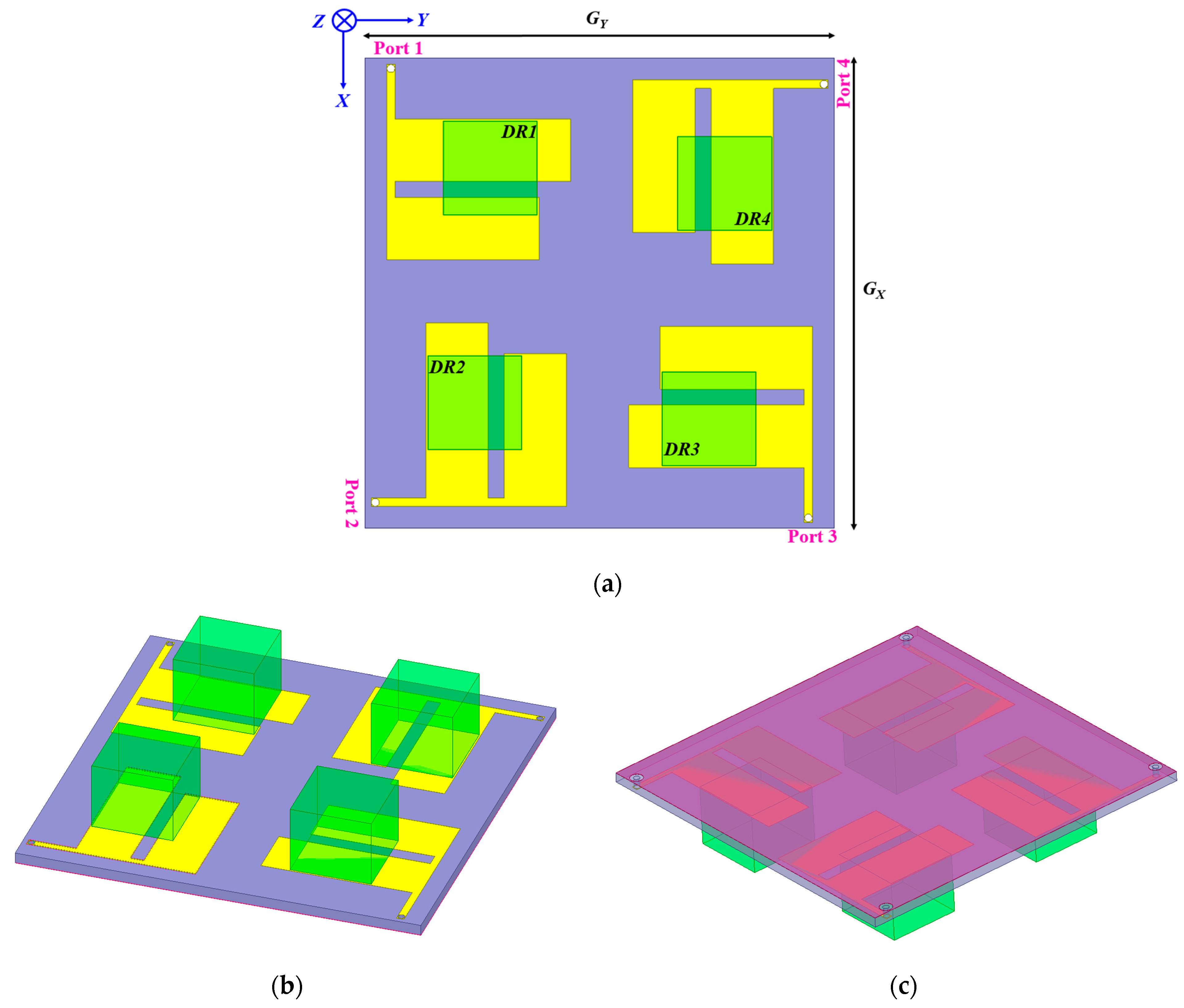
4. MIMO Antenna Design Configuration
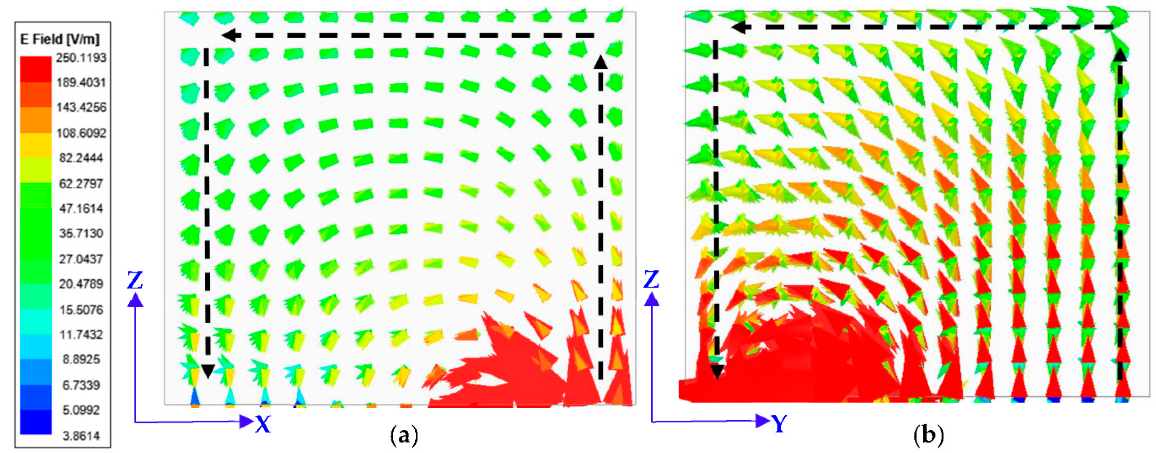
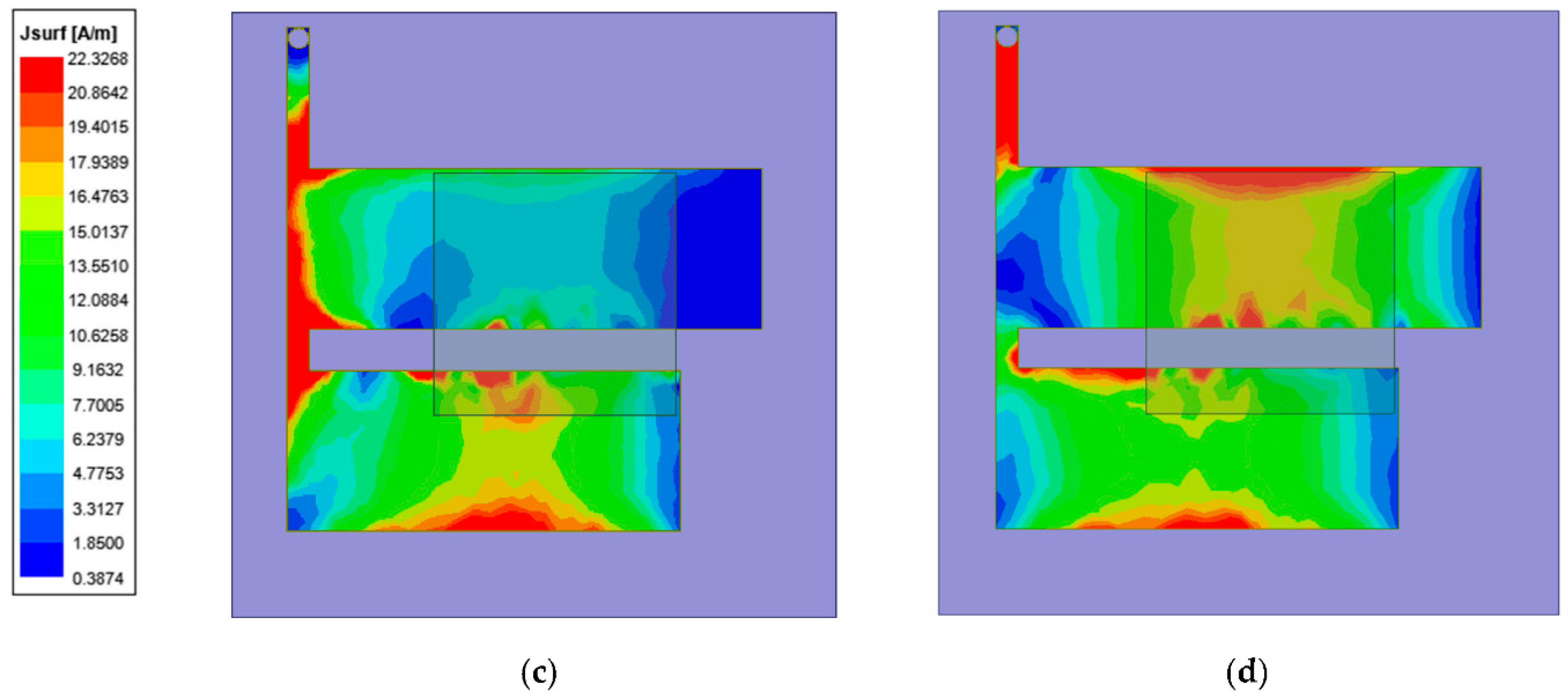
5. Proposed Antenna Results and Discussions
6. Conclusions
Author Contributions
Funding
Data Availability Statement
Conflicts of Interest
References
- Sharawi, M.S. Printed multi-band MIMO antenna systems and their performance metrics [wireless corner]. IEEE Antennas Propag. Mag. 2013, 55, 218–232. [Google Scholar] [CrossRef]
- Karaboikis, M.P.; Papamichael, V.C.; Tsachtsiris, G.F.; Soras, C.F.; Makios, V.T. Integrating compact printed antennas onto small diversity/MIMO terminals. IEEE Trans. Antennas Propag. 2008, 56, 2067–2078. [Google Scholar] [CrossRef]
- Huang, H.; Li, X.; Liu, Y. A low-profile, dual-polarized patch antenna for 5G MIMO application. IEEE Trans. Antennas Propag. 2018, 67, 1275–1279. [Google Scholar] [CrossRef]
- Li, Y.; Zhao, Z.; Tang, Z.; Yin, Y. Differentially fed, dual-band dual-polarized filtering antenna with high selectivity for 5G sub-6 GHz base station applications. IEEE Trans. Antennas Propag. 2019, 68, 3231–3236. [Google Scholar] [CrossRef]
- Le Thi, C.H.; Ta, S.X.; Nguyen, X.Q.; Nguyen, K.K.; Dao-Ngoc, C. Design of compact broadband dual-polarized antenna for 5G applications. Int. J. RF Microw. Comput. Aided Eng. 2021, 31, e22615. [Google Scholar] [CrossRef]
- Chouhan, S.; Panda, D.K.; Kushwah, V.S.; Mishra, P.K. Octagonal-shaped wideband MIMO antenna for human interface device and S-band application. Int. J. Microw. Wirel. Technol. 2019, 11, 287–296. [Google Scholar] [CrossRef]
- Yadav, S.K.; Kaur, A.; Khanna, R. Compact Rack Shaped MIMO Dielectric Resonator Antenna with Improved Axial Ratio for UWB Applications. Wirel. Pers. Commun. 2021, 117, 591–606. [Google Scholar] [CrossRef]
- Girjashankar, P.R.; Upadhyaya, T. Substrate integrated waveguide fed dual band quad-elements rectangular dielectric resonator MIMO antenna for millimeter wave 5G wireless communication systems. AEU-Int. J. Electron. Commun. 2021, 137, 153821. [Google Scholar] [CrossRef]
- Anuar, S.U.; Jamaluddin, M.H.; Din, J.; Kamardin, K.; Dahri, M.H.; Idris, I.H. Triple band MIMO dielectric resonator antenna for LTE applications. AEU-Int. J. Electron. Commun. 2020, 118, 153172. [Google Scholar] [CrossRef]
- Dwivedi, A.K.; Sharma, A.; Singh, A.K.; Singh, V. Circularly polarized quad-port MIMO dielectric resonator antenna with beam tilting feature for vehicular communication. IETE Tech. Rev. 2020, 39, 389–401. [Google Scholar] [CrossRef]
- Alibakhshikenari, M.; Babaeian, F.; Virdee, B.S.; Aïssa, S.; Azpilicueta, L.; See, C.H.; Althuwayb, A.A.; Huynen, I.; Abd-Alhameed, R.A.; Falcone, F.; et al. A comprehensive survey on “Various decoupling mechanisms with focus on metamaterial and metasurface principles applicable to SAR and MIMO antenna systems”. IEEE Access 2020, 8, 192965–193004. [Google Scholar] [CrossRef]
- Wang, Z.; Li, C.; Wu, Q.; Yin, Y. A metasurface-based low-profile array decoupling technology to enhance isolation in MIMO antenna systems. IEEE Access 2020, 8, 125565–125575. [Google Scholar] [CrossRef]
- Bhattacharjee, A.; Karmakar, A.; Saha, A.; Bhattacharya, D. Design of a compact UWB MIMO-diversity antenna incorporating fractal inspired isolation structure with band notch characteristics. Microw. Opt. Technol. Lett. 2021, 63, 2597–2605. [Google Scholar] [CrossRef]
- Yang, Z.; Xiao, J.; Ye, Q. Enhancing MIMO antenna isolation characteristic by manipulating the propagation of surface wave. IEEE Access 2020, 8, 115572–115581. [Google Scholar] [CrossRef]
- Tang, J.; Faraz, F.; Chen, X.; Zhang, Q.; Li, Q.; Li, Y.; Zhang, S. A metasurface superstrate for mutual coupling reduction of large antenna arrays. IEEE Access 2020, 8, 126859–126867. [Google Scholar] [CrossRef]
- Deng, J.Y.; Li, J.Y.; Guo, L.X. Decoupling of a three-port MIMO antenna with different impedances using reactively loaded dummy elements. IEEE Antennas Wirel. Propag. Lett. 2018, 17, 430–433. [Google Scholar] [CrossRef]
- Roy, S.; Chakraborty, U. Mutual coupling reduction in a multi-band MIMO antenna using meta-inspired decoupling network. Wirel. Pers. Commun. 2020, 114, 3231–3246. [Google Scholar] [CrossRef]
- Moussa, K.H.; Amar, A.S.; Mabrouk, M.; Mohamed, H.G. Slotted E-Shaped Meta-Material Decoupling Slab for Densely Packed MIMO Antenna Arrays. Micromachines 2021, 12, 873. [Google Scholar] [CrossRef]
- Li, M.; Cheung, S. A novel calculation-based parasitic decoupling technique for increasing isolation in multiple-element MIMO antenna arrays. IEEE Trans. Veh. Technol. 2020, 70, 446–458. [Google Scholar] [CrossRef]
- Ding, C.F.; Zhang, X.Y.; Xue, C.D. Novel pattern-diversity-based decoupling method and its application to multielement MIMO antenna. IEEE Trans. Antennas Propag. 2018, 66, 4976–4985. [Google Scholar] [CrossRef]
- Kumar, S.; Nandan, D.; Srivastava, K.; Kumar, S.; Singh, H.; Marey, M.; Mostafa, H.; Kanaujia, B.K. Wideband circularly polarized textile MIMO antenna for wearable applications. IEEE Access 2021, 9, 108601–108613. [Google Scholar] [CrossRef]
- Huang, J.; Dong, G.; Cai, J.; Li, H.; Liu, G. A quad-port dual-band MIMO antenna array for 5G smartphone applications. Electronics 2021, 10, 542. [Google Scholar] [CrossRef]
- Pant, A.; Singh, M.; Parihar, M.S. A frequency reconfigurable/switchable MIMO antenna for LTE and early 5G applications. AEU-Int. J. Electron. Commun. 2021, 131, 153638. [Google Scholar] [CrossRef]
- El Hadri, D.; Zakriti, A.; Zugari, A.; El Ouahabi, M.; El Aoufi, J. High isolation and ideal correlation using spatial diversity in a compact MIMO antenna for fifth-generation applications. Int. J. Antennas Propag. 2020, 2020, 2740920. [Google Scholar] [CrossRef]
- Jin, X.; Qiu, Y.; Wu, D.; Yu, G.; Guo, R.; Wu, G.; Zhu, M.; Zhou, H.M. A Low-Profile Dual-Polarized MIMO Antenna with an AMC Surface for WLAN Applications. Int. J. Antennas Propag. 2021, 2021, 9218255. [Google Scholar] [CrossRef]
- Laxman, P.; Jain, A. Circularly Polarized Wideband Fabric Stealth Multiple-Input Multiple-Output Antenna for Ultrawideband Applications Useful for Wireless Systems Wearable on Garments. Int. J. Antennas Propag. 2021, 2021, 1426680. [Google Scholar] [CrossRef]
- Daghari, M.; Essid, C.; Sakli, H. Muli-UWB Antenna System Design for 5G Wireless Applications with Diversity. Wirel. Commun. Mob. Comput. 2021, 2021, 9966581. [Google Scholar] [CrossRef]
- Upadhyaya, T.; Park, I.; Pandey, R.; Patel, U.; Pandya, K.; Desai, A.; Pabari, J.; Byun, G.; Kosta, Y. Aperture-Fed Quad-Port Dual-Band Dielectric Resonator-MIMO Antenna for Sub-6 GHz 5G and WLAN Application. Int. J. Antennas Propag. 2022, 2022, 4136347. [Google Scholar] [CrossRef]
- Ali, A.; Tong, J.; Iqbal, J.; Illahi, U.; Rauf, A.; Rehman, S.U.; Ali, H.; Qadir, M.M.; Khan, M.A.; Ghoniem, R.M. Mutual Coupling Reduction through Defected Ground Structure in Circularly Polarized, Dielectric Resonator-Based MIMO Antennas for Sub-6 GHz 5G Applications. Micromachines 2022, 13, 1082. [Google Scholar] [CrossRef]
- Singhwal, S.S.; Kanaujia, B.K.; Singh, A.; Kishor, J.; Matekovits, L. Multiple input multiple output dielectric resonator antenna with circular polarized adaptability for 5G applications. J. Electromagn. Waves Appl. 2020, 34, 1180–1194. [Google Scholar] [CrossRef]
- Iqbal, A.; Nasir, J.; Qureshi, M.B.; Khan, A.A.; Rehman, J.U.; Rahman, H.U.; Fayyaz, M.A.; Nawaz, R. A CPW fed quad-port MIMO DRA for sub-6 GHz 5G applications. PLoS ONE 2022, 17, e0268867. [Google Scholar] [CrossRef] [PubMed]
- Roshani, S.; Yahya, S.I.; Alameri, B.M.; Mezaal, Y.S.; Liu, L.W.; Roshani, S. Filtering Power Divider Design Using Resonant LC Branches for 5G Low-Band Applications. Sustainability 2022, 14, 12291. [Google Scholar] [CrossRef]
- Sarkar, G.A.; Ballav, S.; Chatterjee, A.; Ranjit, S.; Parui, S.K. Four element MIMO DRA with high isolation for WLAN applications. Prog. Electromagn. Res. Lett. 2019, 84, 99–106. [Google Scholar] [CrossRef] [Green Version]
- Dwivedi, A.K.; Sharma, A.; Singh, A.K.; Singh, V. Design of dual band four port circularly polarized MIMO DRA for WLAN/WiMAX applications. J. Electromagn. Waves Appl. 2020, 34, 1990–2009. [Google Scholar] [CrossRef]
- Varshney, G.; Singh, R.; Pandey, V.S.; Yaduvanshi, R.S. Circularly polarized two-port MIMO dielectric resonator antenna. Prog. Electromagn. Res. M 2020, 91, 19–28. [Google Scholar] [CrossRef]
- Fakhte, S.; Oraizi, H. Compact uniaxial anisotropic dielectric resonator antenna operating at higher order radiating mode. Electron. Lett. 2016, 52, 1579–1580. [Google Scholar] [CrossRef]
- Mukherjee, B.; Patel, P.; Mukherjee, J. Hemispherical dielectric resonator antenna based on apollonian gasket of circles—A fractal approach. IEEE Trans. Antennas Propag. 2013, 62, 40–47. [Google Scholar] [CrossRef]
- Sharma, A.; Biswas, A. Wideband multiple-input–multiple-output dielectric resonator antenna. IET Microw. Antennas Propag. 2017, 11, 496–502. [Google Scholar] [CrossRef]
- Maity, S.; Gupta, B. Experimental investigations on wideband triangular dielectric resonator antenna. IEEE Trans. Antennas Propag. 2016, 64, 5483–5486. [Google Scholar] [CrossRef]


| Parameter | Dimensions (mm) | Parameter | Dimensions (mm) |
|---|---|---|---|
| S1x = S1y | 30 | Lx3 | 7 |
| Dx = Dy | 12 | Wy1 | 19.5 |
| Lx | 2 | Wy2 | 22.4 |
| Lx1 | 25 | Dh | 10 |
| Lx2 | 8 | t | 1.6 |
| Reference | Operating Frequencies (GHz) | Antenna Size (λ) | Isolation (dB) | Gain (dBi) | Fractional Bandwidth (%) | Efficiency (%) | Feed Type |
|---|---|---|---|---|---|---|---|
| [33] | 4.9 | 2.28 × 0.73 × 0.13 | 25 | 6.2 | 5 | -- | Microstrip |
| [34] | 3.22–3.97, 4.95–5.51 | 0.86 × 0.86 × 0.12 | 18, 20 | 5.2, 5.5 | 4.9, 2.3 | 94 | Microstrip |
| [35] | 5.71–8.2, 7.57–7.95 | 1.53 × 1.53 × 0.12 | 20, 15 | −1.9, 3.8 | 34.8, 4.5 | -- | Microstrip |
| [36] | 3.40–4.13 | 1.13 × 1.13 × 0.19 | 14 | 8.1 | 19.4 | 91 | Probe |
| [37] | 3.50–5.10 | 1.43 × 1.43 × 0.36 | -- | 8.5 | 46 | 89 | Probe |
| [38] | 4.56–9.96 | 1.5 × 1.5 × 0.39 | 23 | -- | 73.9 | -- | Trapezoidal Patch |
| [39] | 4.33–7.02 | 2.6 × 2.6 × 0.36 | -- | -- | 48 | 90 | Probe |
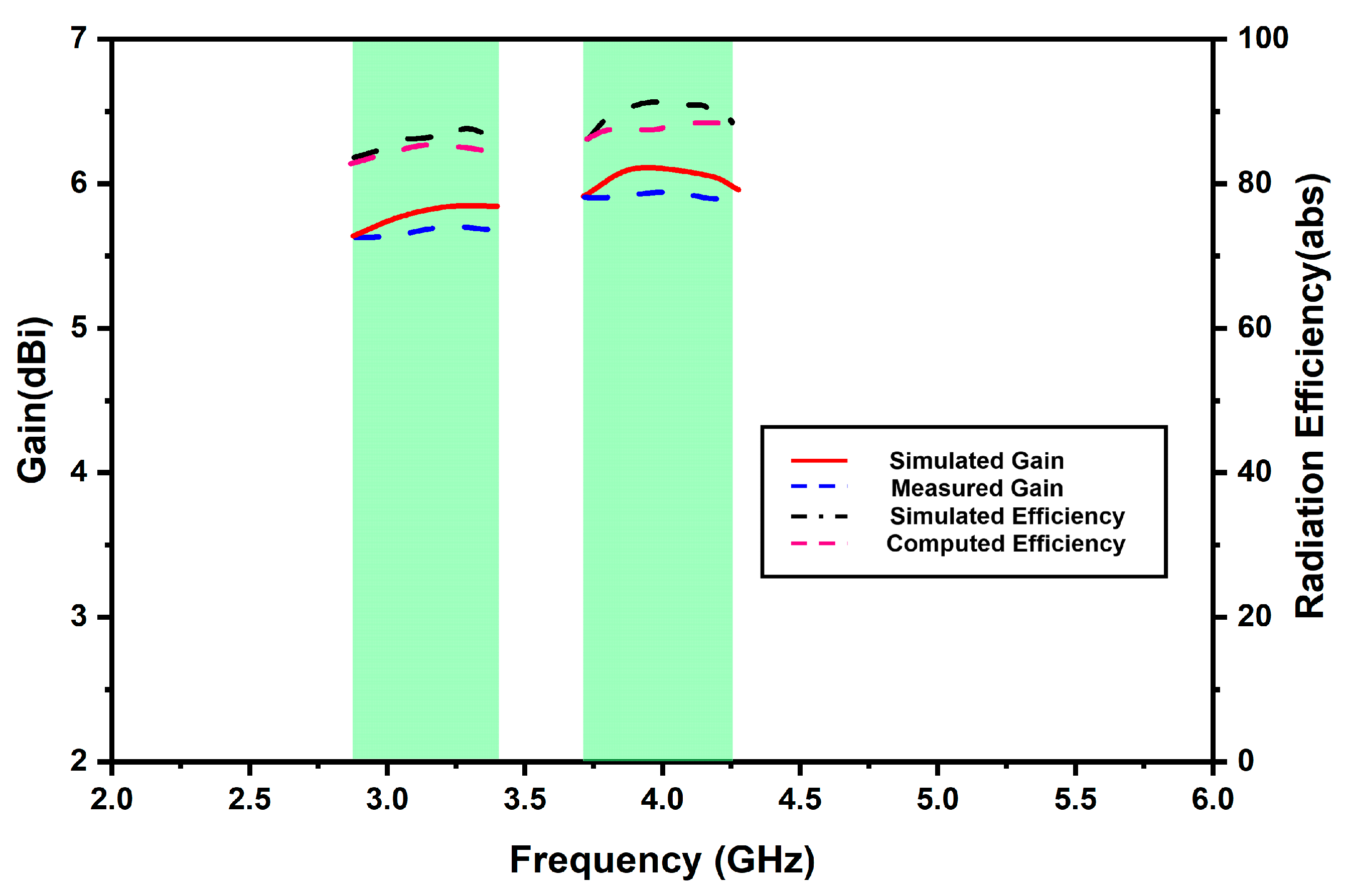
| Proposed Antenna | 2.86–3.48 3.67–4.25 | 0.66 × 0.66 × 0.12 | 20, 26 | 5.8, 6.2 | 18.7, 14.6 | 88.6, 90.2 | Aperture Couple |
Publisher’s Note: MDPI stays neutral with regard to jurisdictional claims in published maps and institutional affiliations. |
© 2022 by the authors. Licensee MDPI, Basel, Switzerland. This article is an open access article distributed under the terms and conditions of the Creative Commons Attribution (CC BY) license (https://creativecommons.org/licenses/by/4.0/).
Share and Cite
Patel, U.; Upadhyaya, T. Four-Port Dual-Band Multiple-Input Multiple-Output Dielectric Resonator Antenna for Sub-6 GHz 5G Communication Applications. Micromachines 2022, 13, 2022. https://doi.org/10.3390/mi13112022
Patel U, Upadhyaya T. Four-Port Dual-Band Multiple-Input Multiple-Output Dielectric Resonator Antenna for Sub-6 GHz 5G Communication Applications. Micromachines. 2022; 13(11):2022. https://doi.org/10.3390/mi13112022
Chicago/Turabian StylePatel, Upesh, and Trushit Upadhyaya. 2022. "Four-Port Dual-Band Multiple-Input Multiple-Output Dielectric Resonator Antenna for Sub-6 GHz 5G Communication Applications" Micromachines 13, no. 11: 2022. https://doi.org/10.3390/mi13112022