1. Introduction
Axial piston pumps are the key components in many hydraulic systems, which are widely used in harsh operating conditions because they can run efficiently under high pressure and at various speeds [
1,
2]. However, during the operation of axial piston pumps, the power loss of the valve plate can reach up to 8%. The main sources of power loss are the friction and leakage of the lubrication interface: the former can reach 5% and the latter can reach 3% [
3,
4]. The friction loss is not only related to the viscosity of hydraulic oil, but also to the textured surface of the lubrication interface [
5]. Understanding how to reduce power loss caused by the valve plate and the design of the lubrication interface are key to improving the efficiency of the piston pump. The surface-texturing technique is a new technology in the field of tribology [
6]. It has obvious positive effects in improving the load-carrying capacity, wear resistance and friction efficiency of friction pairs, and this is widely recognized.
Tribology researchers all over the world have carried out extensive research on the processing, application, lubrication mechanism and optimization design of micro-pit surface textures, and they have obtained a series of achievements in recent decades. It has been found that micro-textured surfaces, such as grooves [
7], asperities [
8], and dimples [
9], can also improve lubrication performance and reduce friction loss. In 2007, French scholar Tala-Ighil studied the radial bearing with a spherical textured surface and found that the friction performance is related to the area ratio, depths and diameter of the micro-texture [
10]. From 2009 to 2013, Wang and Yu conducted a series of experiments and concluded that there is an optimal texture radius that makes the texture effect most obvious compared to the experimental data. In particular, to textures with different shapes, there is an optimal micro-pit area ratio and depth, corresponding to the largest effect [
11,
12,
13,
14]. In 2011, American experts found that textured surfaces can always reduce the friction coefficient to varying degrees [
15]. In 2013, Muthuvel and Rajagopal, as well as Scaraggi and Segu, explored the relationship between micro-textures with different parameters and friction properties and proved that micro-textures can effectively reduce friction coefficients and improve wear resistance [
16,
17,
18,
19]. From Jiangsu University, Fu established a mathematical model of hydrodynamic lubrication for parabolic, triangular and rectangular micro-textured surfaces along a uniform straight line [
20,
21]. The equations of oil film thickness and pressure were derived, then the boundary conditions were given, and the pressure distribution was solved by using the multigrid method. In 2018, Zhang used laser surface texturing (LST) to process micro-textures on a brass column and carried out experimental research on an EHA pump prototype [
22]. It was proved that the texture can improve mechanical efficiency and prototype efficiency, and it was explained that the texture can improve the angle by reducing wear and cylinder inclination. The next year, Chen optimized the micro-texture, further improved the efficiency of the pump, and evaluated the parameters of the texture [
23]. In 2020, Ye found a textured slipper with an area density and a dimple-depth-to-diameter ratio of 24% and 0.3, which can provide a greater load-carrying capacity when taking into account the textured-surface deformation [
24].
In recent years, there has been a lot of research on the lubrication models of the valve plate pair of pumps. Bergada pointed out the relationship between oil-film-thickness and oil-film-pressure distribution and studied the leakage between the cylinder block and the valve plate [
25,
26]. According to the Reynolds equation, Chao derived the pressure formula of the valve plate pair and the distribution of the pressure and temperature was analyzed numerically [
27]. Lin used computational fluid dynamics (CFD) software to analyze the pressure and temperature of the oil film [
28]. In summary, the effect of micro-texture on friction efficiency was studied. However, there are few studies on the optimization of texture structure.
In this paper, the authors established a coupled numerical lubrication model of a cylinder block and the valve plate of an axial piston pump, based on considerations of rectangle micro-textures. Combined with thermohydrodynamic theory, the finite difference method was used to solve the Reynolds equation and energy equation by using the difference quotient of pressure and temperature between nodes, instead of reciprocals. Then, the discrete pressure and temperature values were calculated by FORTRAN (FORTRAN95, IBM, Armonk, NY, USA) procedures. Through continuous iterative coupling, the accuracy of the calculation results was improved and the numerical results within the allowable error range was obtained. Additionally, the nephograms of pressure, temperature and elastic deformation distribution were made by MATLAB (MATLAB2018, MathWorks, Natick, MA, USA). This makes it convenient for us to observe the change trend.
Finally, by means of the control variable method, the influence of the cylinder rotational speed, tilt angle, oil viscosity, thickness, texture lengths and depths on the friction characteristics of non-textured and textured surfaces of the valve plate were calculated and analyzed. These conclusions lay a foundation for improving the design of valve plates.
2. Model and Theory
2.1. Model Building
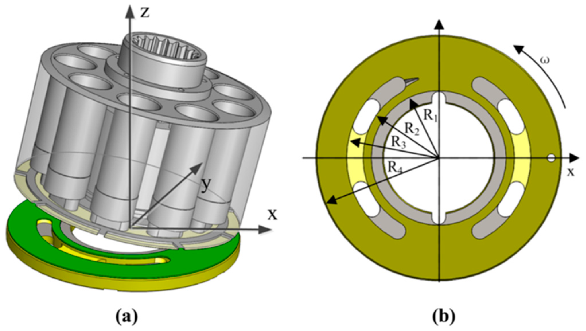
During the operation of the piston pump, due to the high-speed rotation of the cylinder block relative to the valve plate, the offset load moment on the cylinder block makes it tilt to one side along a certain central axis, as shown in
Figure 1a. The friction interface between the cylinder block and the valve plate is annular, and there are regularly arranged micro-pits on the friction surface of the valve plate, the size of which is shown in
Figure 1b. In order to calculate the annular oil film characteristics conveniently, the rectangular coordinate system is transformed into a polar coordinate system, and the conversion rules are as follows:
= circumference angle
= radius
Assuming that the inclination angle between the cylinder block and the valve plate is
, the following oil-film-thickness formula can be obtained:
= thickness of oil film
= initial oil film thickness
= cylinder block tilt angle
Figure 1.
Model of valve plate pair of the piston pump. (a) Structure diagram; (b) Schematic of the main dimensions.
Figure 1.
Model of valve plate pair of the piston pump. (a) Structure diagram; (b) Schematic of the main dimensions.
The micro-pits are arranged regularly on the friction surface of the valve plate. The shape and size of the texture are shown in
Figure 2. It can be seen from
Figure 2a that the depth of the texture is
.
Figure 2b shows a square texture, and its side length is
;
Figure 2c shows a triangular texture, and its side length is
; and
Figure 2d shows a circular texture and its radius is
.
The Reynolds equation in this study is derived from the Navier–Stokes equation for incompressible flow; therefore, it is necessary to make assumptions about the oil film in the valve plate pair before solving the Reynolds equation. The assumptions are as follows:
Lubricating oil is treated as an incompressible fluid.
The lubricating oil is Newtonian fluid.
The inertial force can be ignored.
Oil film pressure remains constant along the -axis.
2.2. Solving Formula of Theory
The oil film pressure of the valve plate pair is governed by the Reynolds equation and the generalized Reynolds equation is expressed as [
29]:
According to the assumptions in
Section 2.1, Equation (3) can be simplified, obtaining a simplified Reynolds equation as:
The simplified Reynolds equation in rectangular coordinates is transformed into a form of polar coordinates. Equation (1) can be replaced with Equation (4) to obtain the following formula:
= working pressure
= viscosity of oil film
= velocity of rotation
Equation (5) can be written as follows:
The temperature distribution of the lubricating oil film can be obtained by numerically solving the energy equation, and the two-dimensional energy equation can be taken as:
Trans Equation (10), which changed rectangular coordinates to polar coordinates, obtains this:
= working temperature of oil
= volume flowrate in direction
= volume flowrate in direction
= mechanical equivalent of heat
= density of lubricating oil
= specific heat capacity of lubricating oil
Discretize Equation (11):
Equation (12) can be simplified as:
Boundary conditions:
Under the influence of pressure and temperature, the viscosity of the lubricating oil will also change. It is usually expressed by Roelands formula:
= viscosity of oil film
= initial viscosity of oil film
= initial temperature of oil
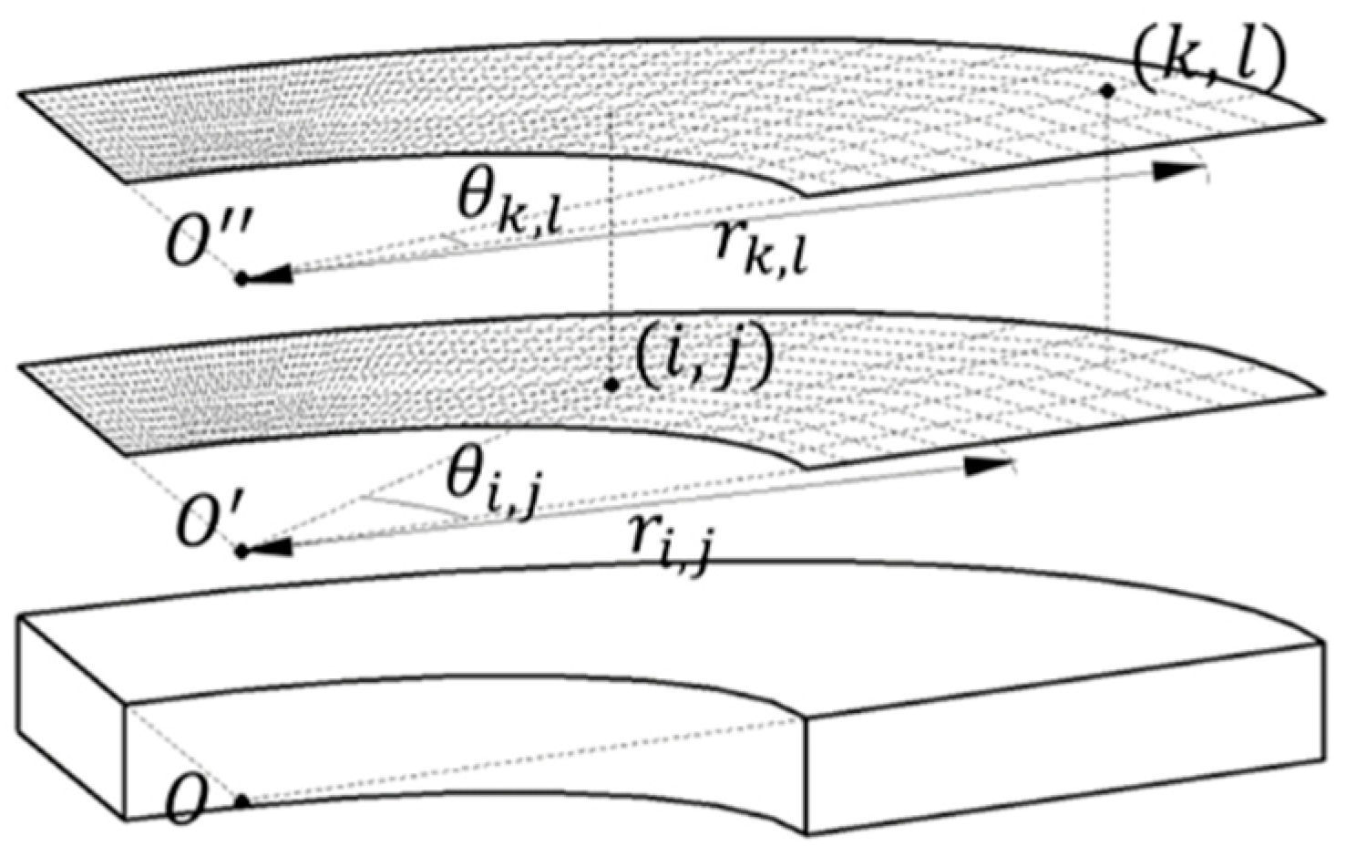
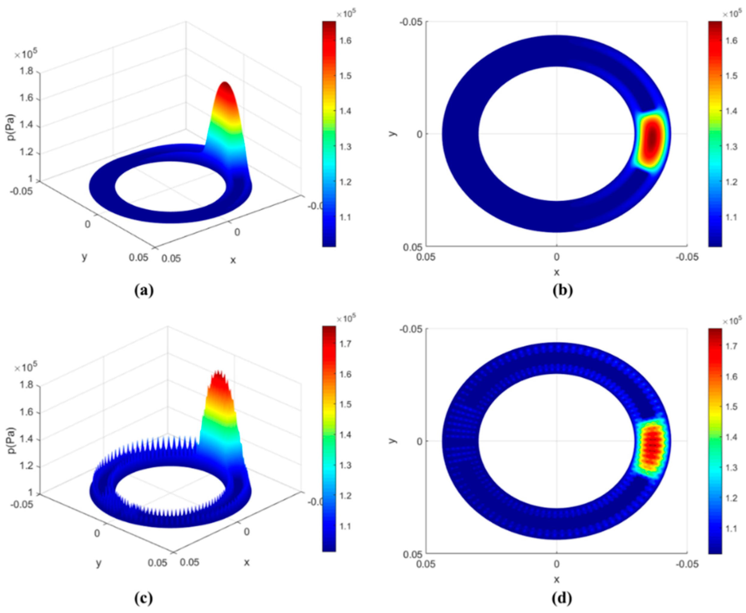
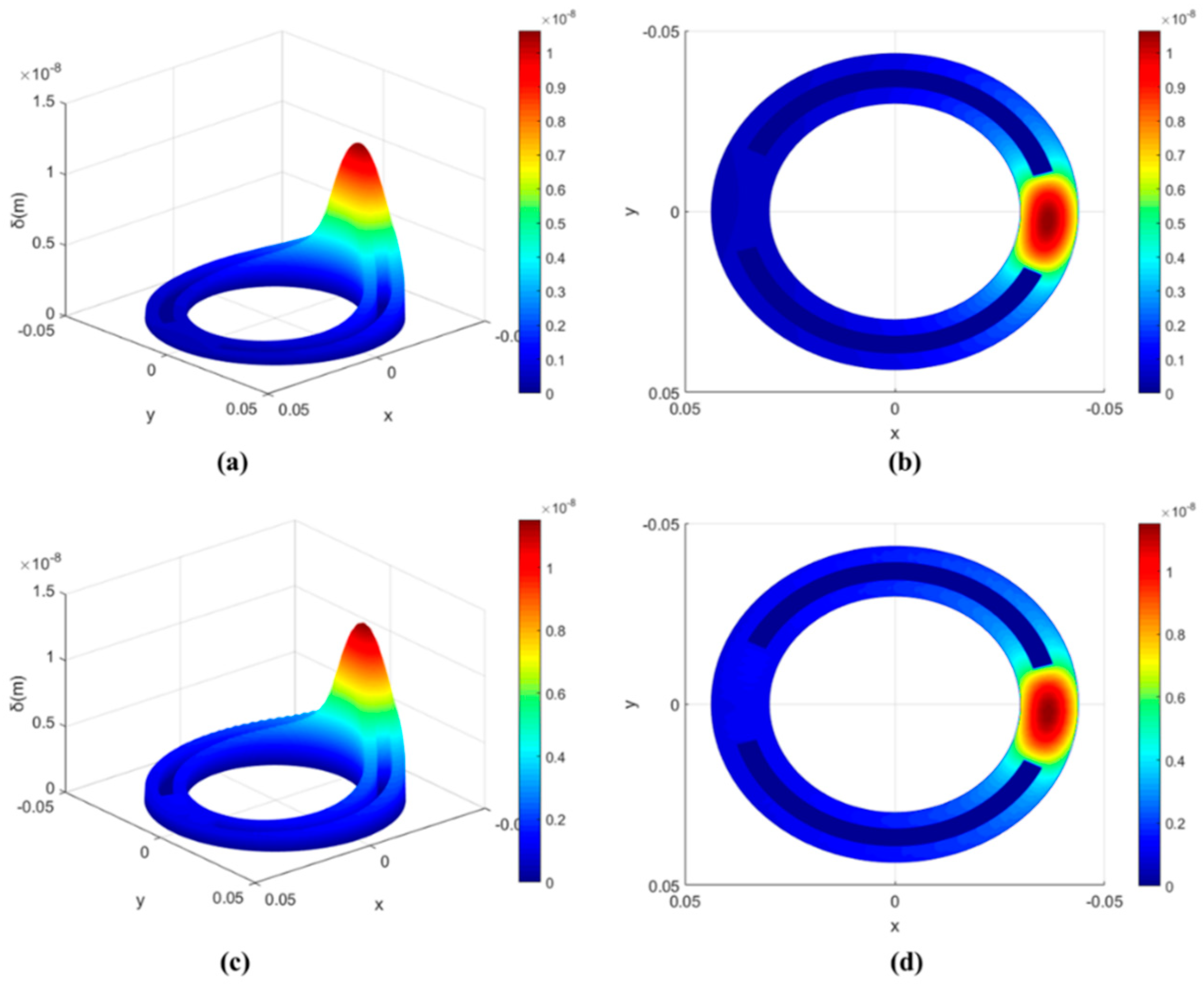
The wedge of the oil film is formed by the inclination of the cylinder block that provides the base for the hydrodynamic effect. As a result, the distribution of oil film pressure is single-peak-like, concentrated on one side of the oil film. Due to the concentration of pressure distribution, the valve plate has an elastic deformation, which needs to be calculated according to the elastic deformation theory. As shown in
Figure 3, the elastic deformation
of node
in plane
caused by node
in plane
was taken as:
Convert the coordinate system to a cylindrical coordinate system and discretize Equation (16):
When nodes (
) and (
) are the same point, replace node (
) with (
) in the process of calculating the distance:
Therefore, the total elastic deformation at node (
) is as follows:
where
= elastic deformation
= number of nodes in circumferential direction
= number of nodes in radius direction
= comprehensive elastic modulus
= elastic modulus of the valve plate
= elastic modulus of the cylinder block
= Poisson’s ratio of valve plate
= Poisson’s ratio of cylinder block
Simplify Equation (18) as follows:
2.3. Numerical Calculations
In this paper, the finite difference method is used to solve the mathematical model. The Reynolds equation and energy equation are discretized by the central difference method. More concretely, difference coefficients are used to replace derivatives of the Reynolds equation and energy equation, which improves the accuracy of the calculation. Concurrently, the numerical solutions of pressure and temperature of oil film are obtained by the relaxation iteration method. The convergence condition is taken as:
where
is an accuracy error of
and
is the number of iterations.
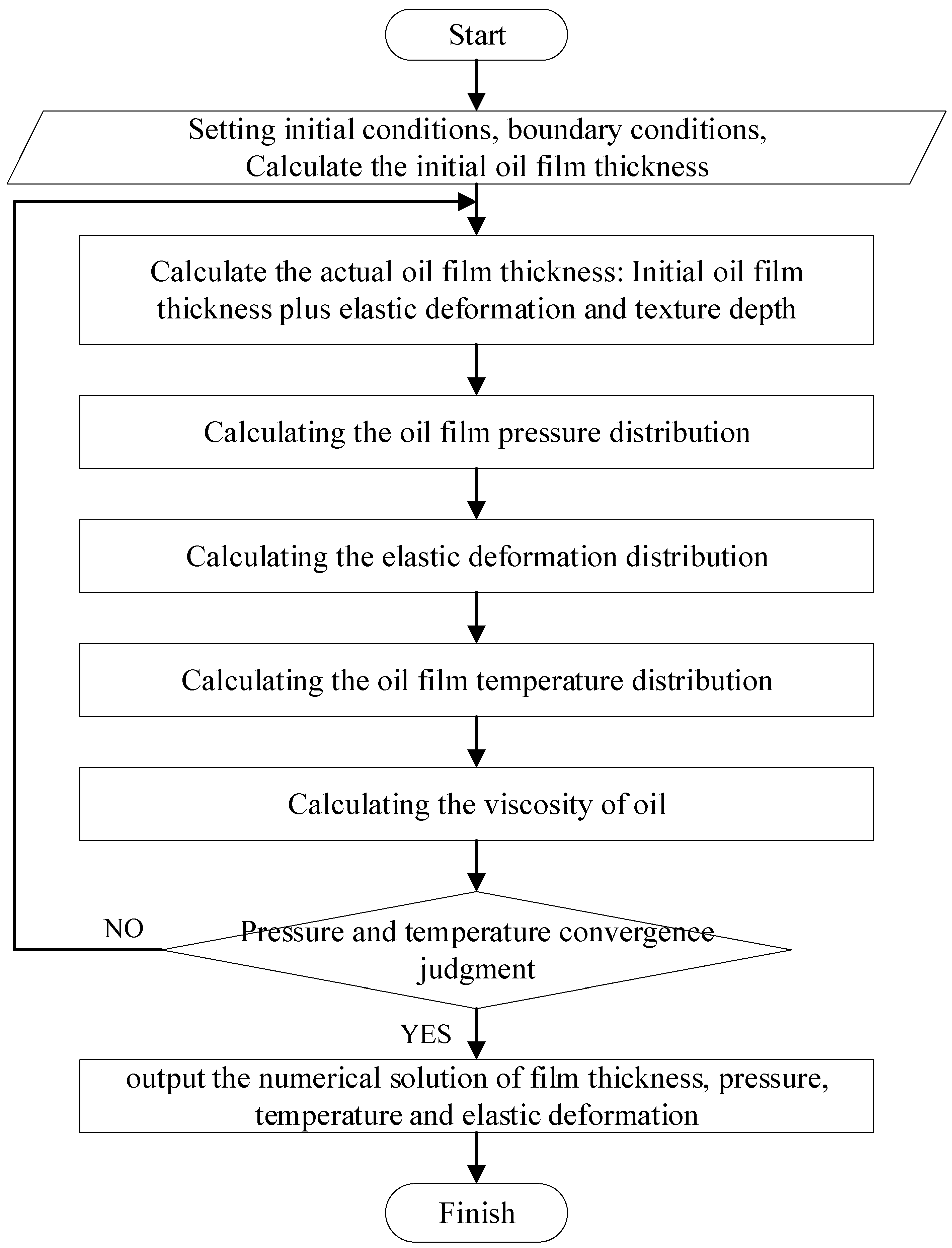
Firstly, the initial conditions of the valve plate parameters and the operating conditions are set. Secondly, according to the oil-film-thickness formula, the oil film thickness of each node is calculated, which is substituted into the Reynolds equation to calculate the pressure distribution of the lubricating oil film. According to the pressure of each node, the elastic deformation of the valve plate is calculated by substituting it into the elastic deformation equation. Finally, the obtained numerical solution is brought into the energy equation to obtain the temperature distribution of the lubricating oil film. At this time, it is judged whether the numerical solution meets the required accuracy requirements. If it does not meet the requirements, the results will be brought back into the calculation.
The flowchart of the numerical calculation procedures for oil film pressure, temperature and elastic deformation is shown in
Figure 4.
4. Friction Characteristics
Compared with the non-textured surface of the valve plate, the texture on the valve plate can improve the load-carrying capacity and friction efficiency of the oil film in different degrees, but the textured structure needs to be adjusted continuously for simulation experiments. Through the comparison of the data results, the best parameters can be found to improve the friction reduction effect as much as possible.
In this section, the friction characteristics values under different valve plate pair parameters and texture structure parameters are calculated, such as the maximum pressure of the oil film, the load-carrying forces, the friction force of the lubricating oil during operation and the friction coefficient.
4.1. Influence of Valve Plate Pair Parameters
The initial parameters in
Table 1 remain unchanged, except for cylinder block rotation speeds, cylinder block inclination angles, initial film thicknesses and initial oil viscosities.
Cylinder block rotation speeds are taken as: 1000 ; 1500 ; 2000 ; 2500 ; 3000 ; 3500 ; 4000 ; 4500 ; and 5000 .
Cylinder block inclination angles are taken as: 0.002; 0.003; 0.004; 0.005; 0.006; 0.007; 0.008; 0.009; and 0.010.
The initial film thicknesses are taken as: 17.5 ; 22.5 ; 27.5 ; 32.5 ; 37.5 ; 42.5 ; and 47.5 .
The initial oil viscosities are taken as: 0.0165 ; 0.0265 ; 0.0365 ; 0.0465 ; 0.0565 ; 0.0665 ; and 0.0765 .
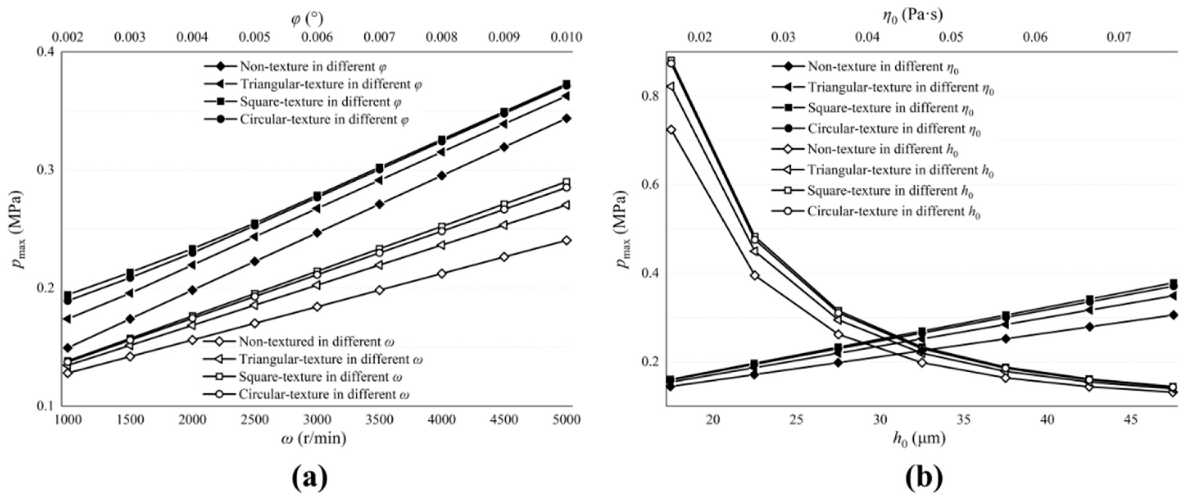
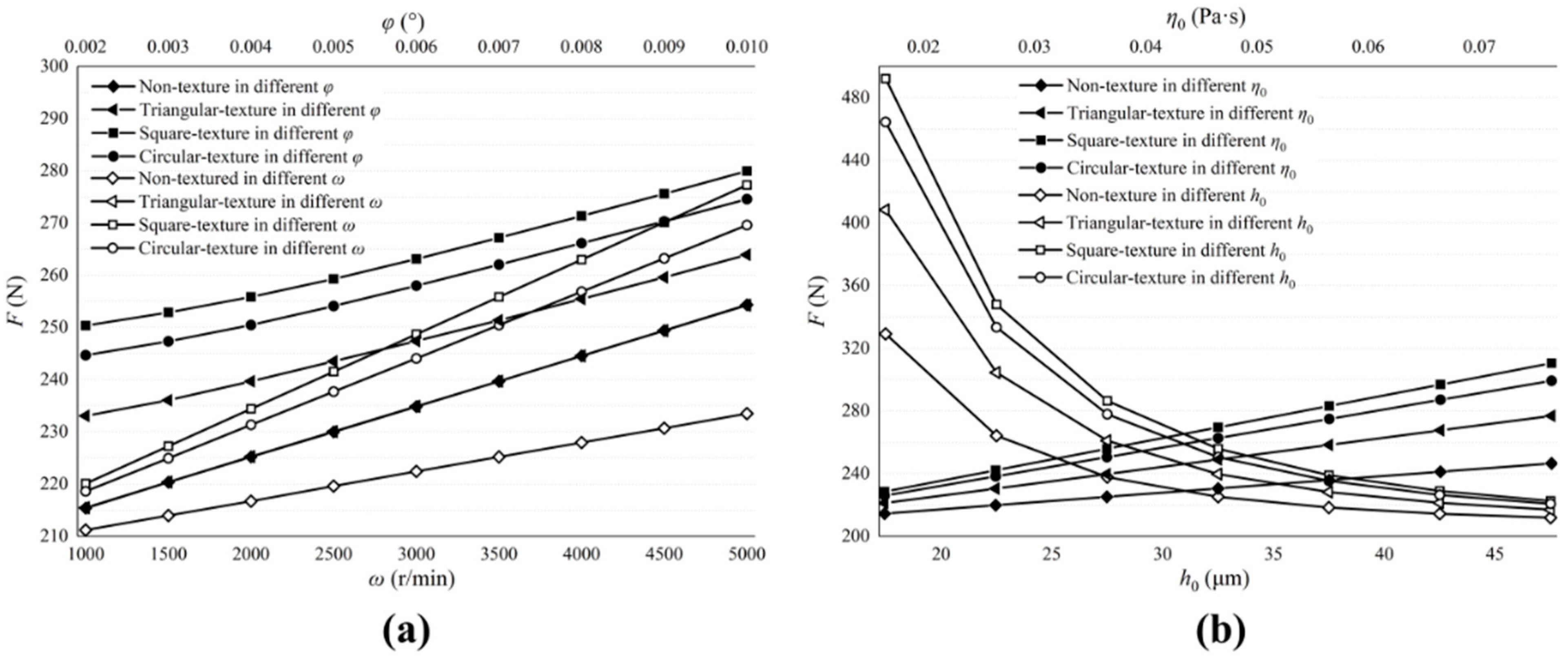
Figure 10 and
Figure 11 describe the influence of the valve plate pair parameters on the maximum film pressure and load-carrying forces.
Figure 10a and
Figure 11a show the influence of
and
.
Figure 10b and
Figure 11b show the influence of
and
. Among them, influence factors,
,
and
are positively correlated with the maximum oil film pressure and load-carrying forces, while
is the opposite. The larger the inclination angle of the cylinder block, the stronger the convergence of the oil film thickness in the thin oil film area, which makes the flow hydrodynamic effect more obvious, similar to the increase in cylinder speed, and causes pressure and forces to amplify.
The biggest impact on the maximum pressure and load-carrying forces are the initial film thicknesses. Reducing thicknesses can greatly increase pressure and forces and, when thicknesses are large enough, the flow hydrodynamic effect is not obvious and almost disappears.
The textured surface of the valve plate can produce larger oil film pressure and load-carrying forces, and the pressure and forces on the circular textured surface is the largest, while the triangular textured surface is the smallest.
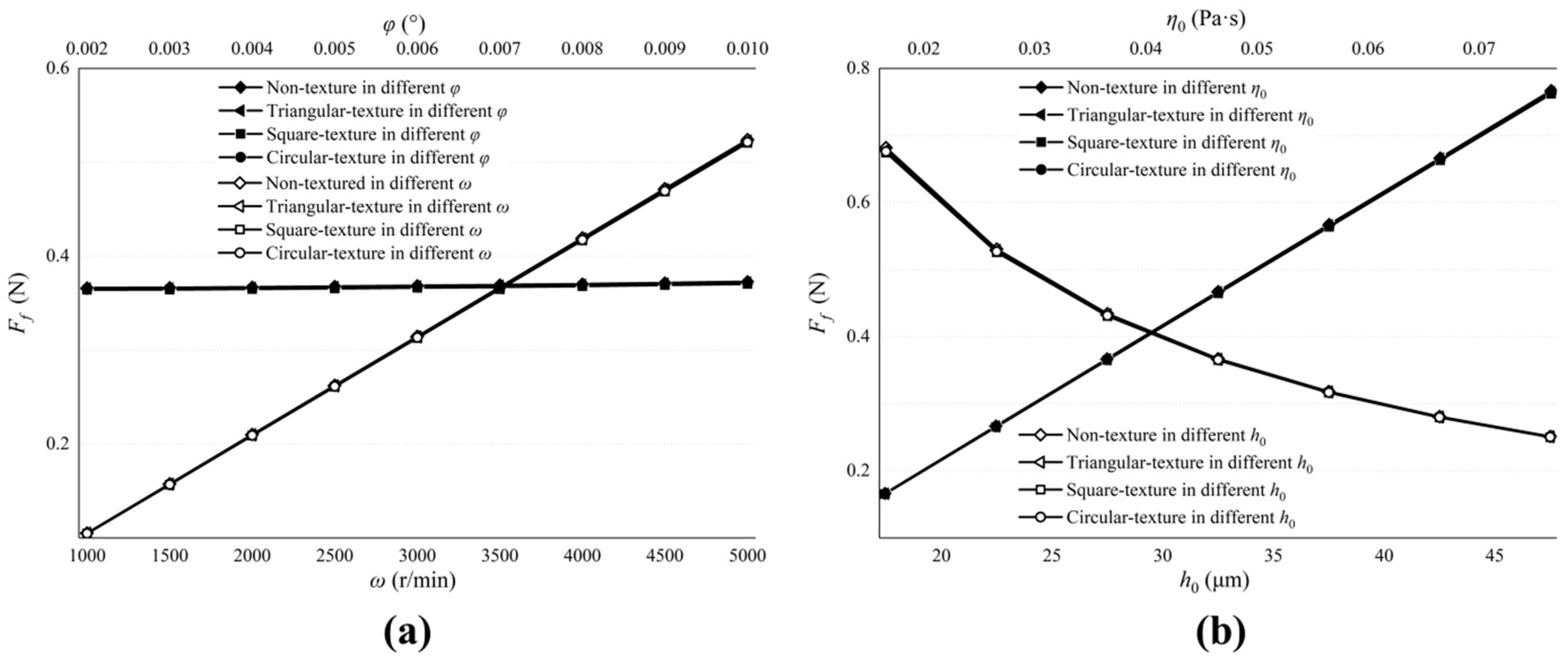
Figure 12 describes the influence of valve plate pair parameters on the friction forces.
Figure 12a shows the influence of
and
.
Figure 12b shows the influence of
and
. The friction forces increase with the increase in
and
, but when
increases, the friction decreases. At the same time, we notice that no matter how much
increases, the change in friction forces is very small. The best way to reduce friction forces is to reduce the initial oil viscosity, but this will lead to smaller load-carrying forces. In actual operating conditions, the appropriate viscosity of the lubricating oil should be selected.
No matter how the parameters of the valve plate pair change, the non-textured and textured surfaces of the valve plate are almost the same for the friction forces.
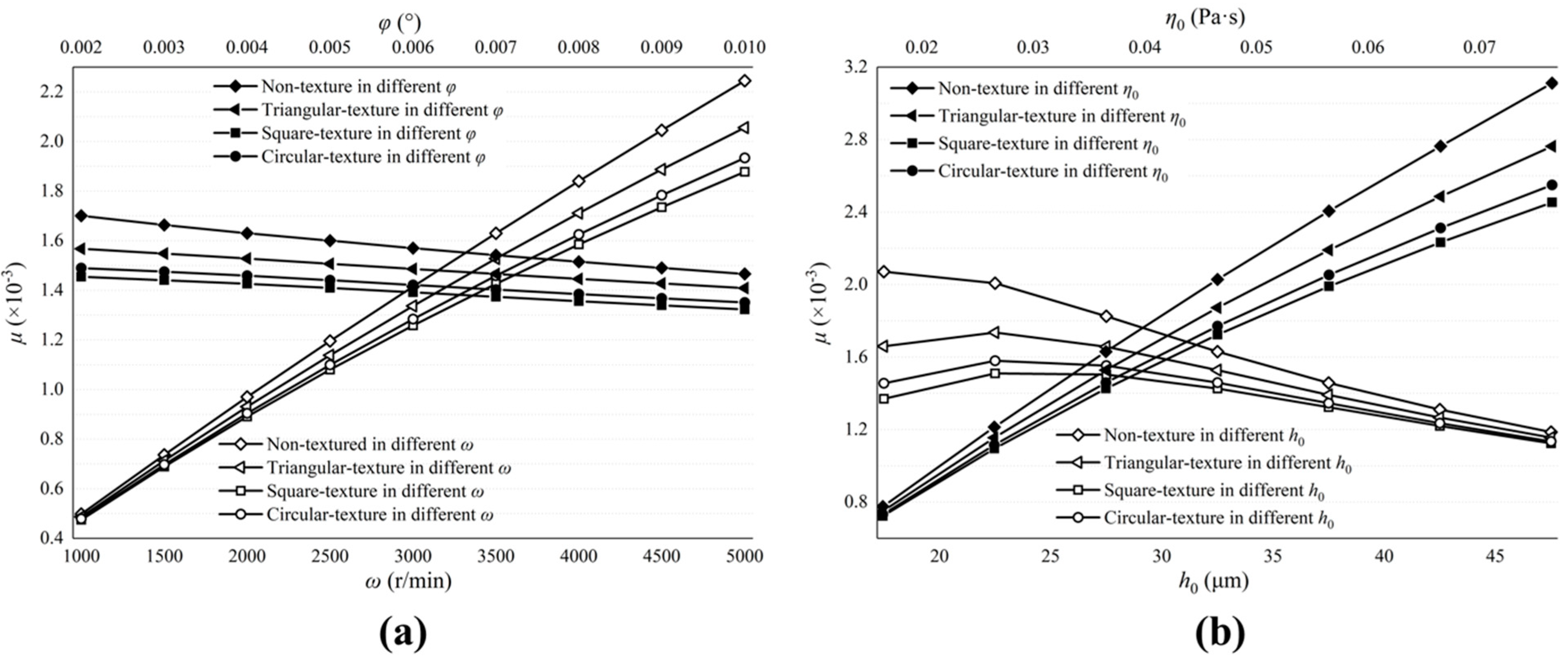
Figure 13 describes the influence of the valve plate pair parameters on the friction coefficient.
Figure 13a shows the influence of
and
.
Figure 13b shows the influence of
and
. Reducing ω can diminish the friction coefficient and improve the friction efficiency. It has the same effect as reducing the viscosity of the lubricating oil. Although increasing the inclination angle of the cylinder block and the initial oil film thickness can also improve friction efficiency, the result is not obvious and this may lead to an increase in cylinder leakage and a reduction in the volumetric efficiency of the pump.
4.2. Influence of Texture Structural Parameters
From
Section 4.1, we noticed that the friction characteristics of differently shaped textured valve plate surfaces are distinctive, so it can be inferred that changing the micro-pit parameters will also bring about different friction characteristics. The initial parameters in
Table 1 remain unchanged, but the lengths or radii and depths of the micro-pits changed.
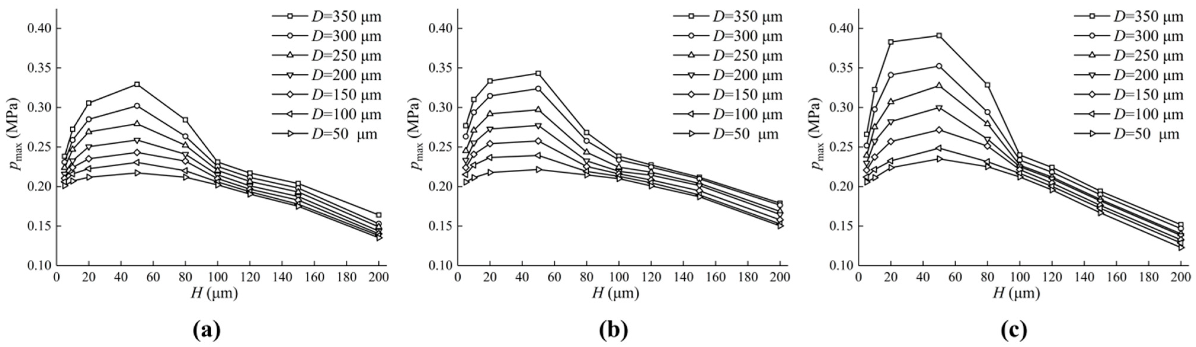
Figure 14 shows the effect of different textures on the maximum pressure of the oil film. It can be seen from the figure that, with the increase in texture depth, the maximum pressure of the oil film increases firstly and then decreases. The maximum value of pressure appears near H at 50
, and the larger D is, the greater the maximum pressure will be. Compared with
Figure 14a–c, it was found that the maximum oil film pressure on the valve plate surface of a circular texture is the largest, followed by that of a square texture. The smallest was that of a triangular texture. The specific texture structure parameters are shown in
Table 2:
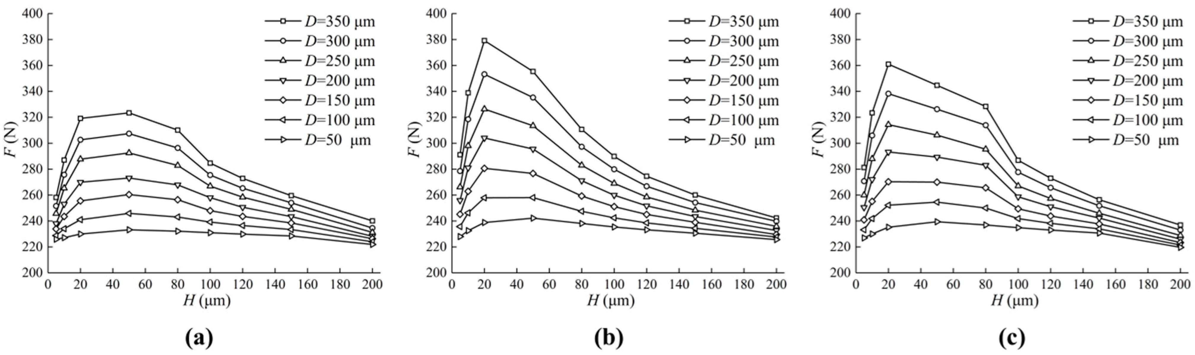
Figure 15 shows the effect of different textures on the load-carrying forces. The change trend in the load-carrying forces of the oil film are the same as the maximum oil film pressure. When H is between 20
and 40
, there is a maximum load-carrying force of the oil film, and the larger D is, the greater the forces are. Compared with the triangular textured valve plate surface, the square textured and circular textured valve plate surface provide greater load-carrying forces.
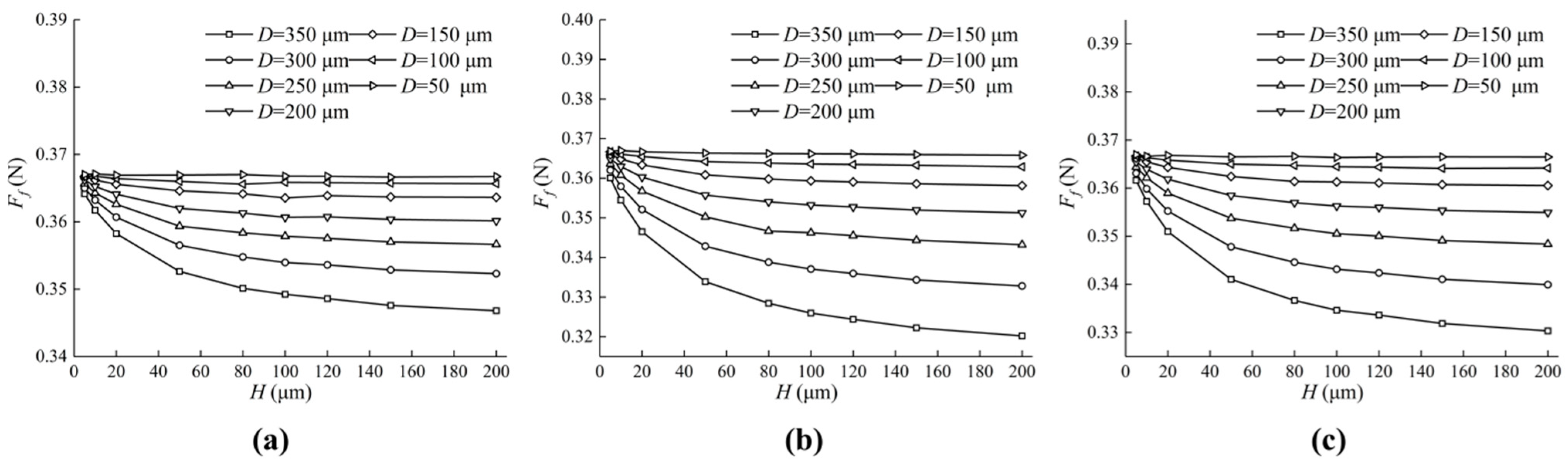
Figure 16 shows the effect of different textures on the friction forces. Enlarging
and
leads to a decrease in friction forces. However, the friction forces decrease little with the increase in
when
is small enough (50
, 100
). In addition, the friction forces of the valve plate of a square texture and of a circular texture is smaller than that of a triangular texture.
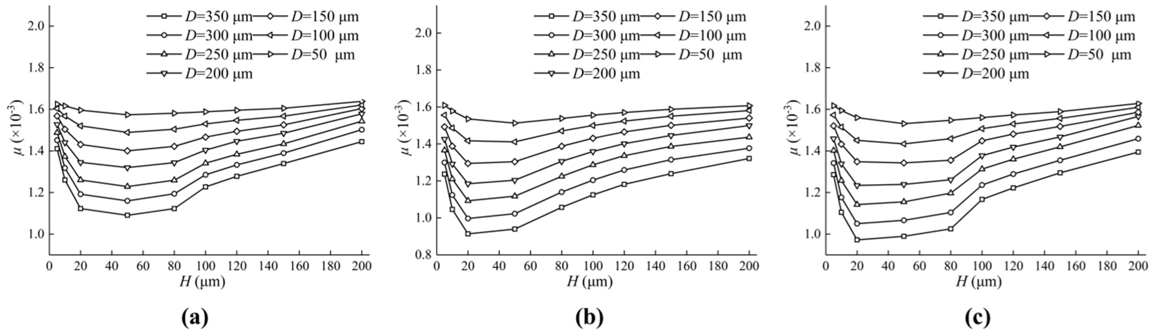
Figure 17 shows the effect of different textures on the friction coefficient. The friction coefficient decreases with the increase in
from 5
to 50
, and the continuous increase in
brings about the increase in
, which can be seen in
Figure 17. When
changes from 20
to 40
, there is a minimum value of the friction coefficient, which makes the friction efficiency the highest. The larger
is, the smaller the friction coefficient and the higher the friction efficiency.
Under the same operating conditions, the friction efficiency of the square texture and the circular texture is higher than that of the triangular texture.
5. Conclusions
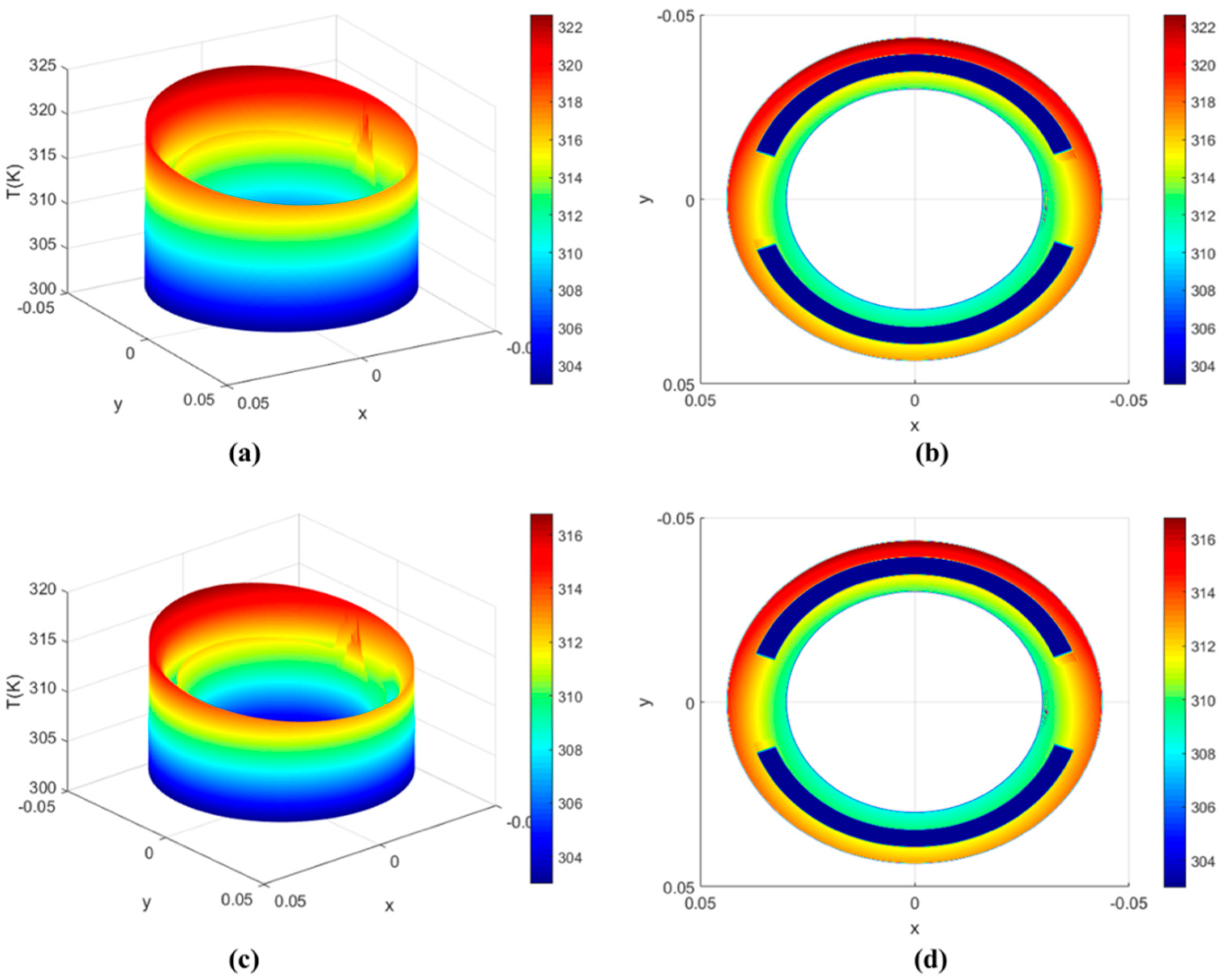
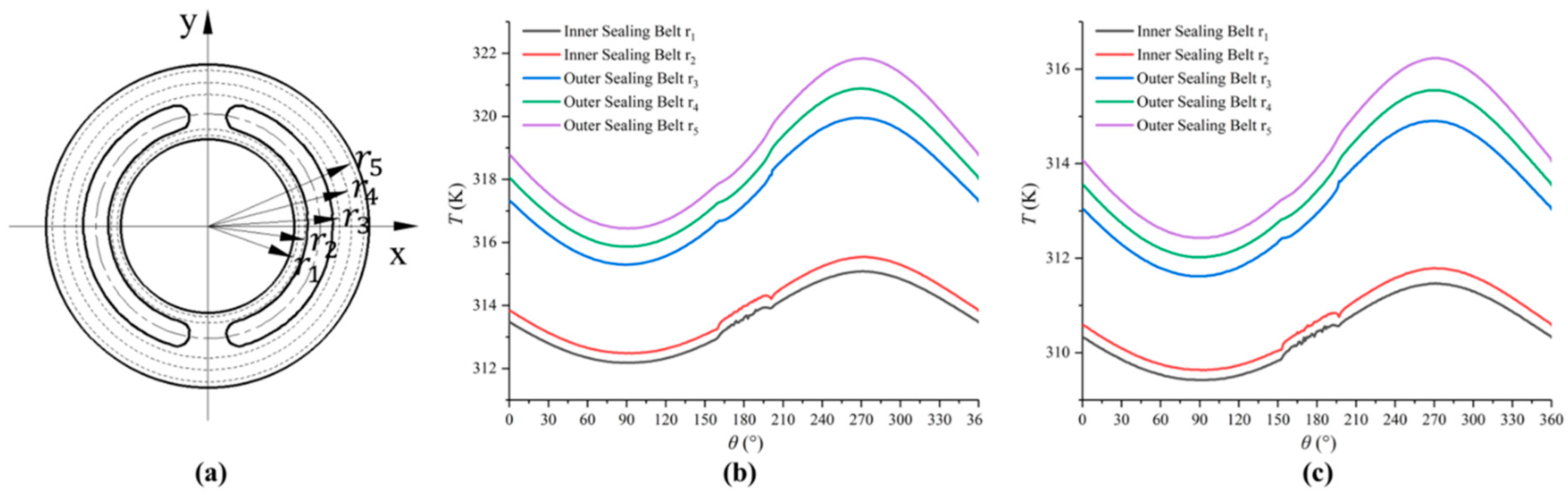
Due to the rotation of cylinder block rotation, the cylinder block inclines to different degrees, which leads to a wedge-shaped oil film with a different thickness. On the inclined side, the oil film thickness reaches the minimum and the hydrodynamic effect is produced under the flow of oil, and the maximum oil film pressure, temperature and elastic deformation are produced in the same region. By comparing the simulation results of the oil film in the textured surface of the valve plate, it is found that the oil film lubrication interface of the valve plate pair with texture can significantly improve the hydrodynamic effect and load-carrying forces. The specific conclusions are as follows:
At the same angular velocity, the larger the radius is, the greater the linear velocity is. Because the friction power is converted into heat energy, the temperature of the oil film increases with the increase in radius. Because the temperature can significantly affect the viscosity of oil and change the pressure distribution and oil film load-carrying forces, the oil film temperature distribution is an important factor affecting lubrication performance.
The maximum film pressure, elastic deformation and temperature can be affected by the initial film thickness, cylinder inclination angle, oil viscosity and rotating speed, and the initial film thickness has the greatest influence on the maximum pressure and elastic deformation, while the inclination angle of the cylinder block has the greatest influence on the maximum oil film temperature.
Under the same operating conditions, the textured surface of the valve plate has larger pressure, elastic deformation, load-carrying forces and a smaller temperature than the non-textured surface.
With the increase in micro-texture depth, the friction efficiency increases first and then decreases, and the friction efficiency reaches the maximum between 20 and 80 . In addition, the friction efficiency of the textured surface is always higher than the non-textured surface under the same operating conditions.
The friction efficiency can be improved by three different textures. What we noticed is that the friction coefficient of the circular textured surface is smaller, the friction efficiency is higher and the triangular textured surface is the worst.


