Article

Refractive Index Sensor Based on the Fano Resonance in Metal–Insulator–Metal Waveguides Coupled with a Whistle-Shaped Cavity

1
School of Software, North University of China, Taiyuan 030051, China
2
Key Laboratory of Instrumentation Science & Dynamic Measurement of Ministry of Education, North University of China, Taiyuan 030051, China
3
School of Physical Science and Technology, Lingnan Normal University, Zhanjiang 524048, China
4
School of Electrical and Control Engineering, North University of China, Taiyuan 030051, China
*
Authors to whom correspondence should be addressed.
Micromachines 2022, 13(10), 1592; https://doi.org/10.3390/mi13101592
Submission received: 2 September 2022 / Revised: 19 September 2022 / Accepted: 21 September 2022 / Published: 25 September 2022
(This article belongs to the Special Issue Flexible and Wearable Sensors)

Abstract

:
A plasmonic refractive index sensor based on surface plasmon polaritons (SPPs) that consist of metal–insulator–metal (MIM) waveguides and a whistle-shaped cavity is proposed. The transmission properties were simulated numerically by using the finite element method. The Fano resonance phenomenon can be observed in their transmission spectra, which is due to the coupling of SPPs between the transmission along the clockwise and anticlockwise directions. The refractive index-sensing properties based on the Fano resonance were investigated by changing the refractive index of the insulator of the MIM waveguide. Modulation of the structural parameters on the Fano resonance and the optics transmission properties of the coupled structure of two MIM waveguides with a whistle-shaped cavity were designed and evaluated. The results of this study will help in the design of new photonic devices and micro-sensors with high sensitivity, and can serve as a guide for future application of this structure.

1. Introduction

Surface plasmon polaritons (SPPs) have the capability of overcoming the diffraction limit due to their energy evanescently confining in the perpendicular direction of the metal–insulator interference [1,2,3]. SPPs have been widely used in surface-enhanced Raman scattering, imaging, solar cells, sensors, optical filters [4,5,6,7,8,9,10], and so on. Recently, another new type of surface plasmon, Tamm plasmon modes in the metal-PhC cavity, has shown excellent performance in gas sensors and refractive index sensors due to its sensitivity to the environment and strong localization [11,12,13]. For the application of manipulating SPPs in chip-scale integration, metal–insulator–metal (MIM) waveguides are an excellent subwavelength photonic device [14,15]. A plasmonic interferometric biosensor based on MIM waveguides for phase-sensitive biomolecular analysis has been proposed [16]. SPP photonic devices based on MIM waveguides have received increasing attention, such as all-optical switches, sensors, and slow light devices [17,18,19].
Recently, the Fano resonance phenomenon was observed in the MIM waveguide-coupled resonator system [20,21]. It was first discovered by Fano Ugo, and has an asymmetric line profile due to the interference between a narrow discrete resonance and a broad spectral line or continuum [22,23,24]. Fano resonance, as a weak coupling and interference phenomenon, has a unique line shape, which provides a promising pathway to achieve ultrahigh sensitivity sensors, lasing, all-optical switching, and nonlinear and slow light [25,26,27,28,29,30,31]. Biosensors and chemical sensors based on Fano resonance have attracted much attention from researchers due to their extreme sensitivity to changes in structural parameters and the surrounding dielectrics [32,33]. These sensors exhibit good performance in terms of sensitivity and figure of merit (FOM) [34,35]. To achieve ultrahigh sensitivity, these structures and parameters need to be optimized. Therefore, the way in which to optimize the MIM waveguide-coupled resonator system to obtain a plasmonic coupled system with a Fano line shape is a key issue for designing high-sensitivity plasmonic sensors.
In this study, a whistle-shaped plasmonic structure composed of one whistle-shaped cavity and an MIM waveguide was designed to obtain high-sensitivity sensors based on Fano resonance. The transmission properties and magnetic field distributions of the whistle-shaped structures were simulated using the finite element method (FEM). The effects of the structural parameters of the whistle-shaped structure on the transmission spectrum were investigated. The refractive index sensitivity and the FOM of the whistle-shaped structure were explored. A derived plasmonic structure composed of a double whistle-shaped coupled structure was designed and evaluated. The sensitivity of the derived structure was examined.

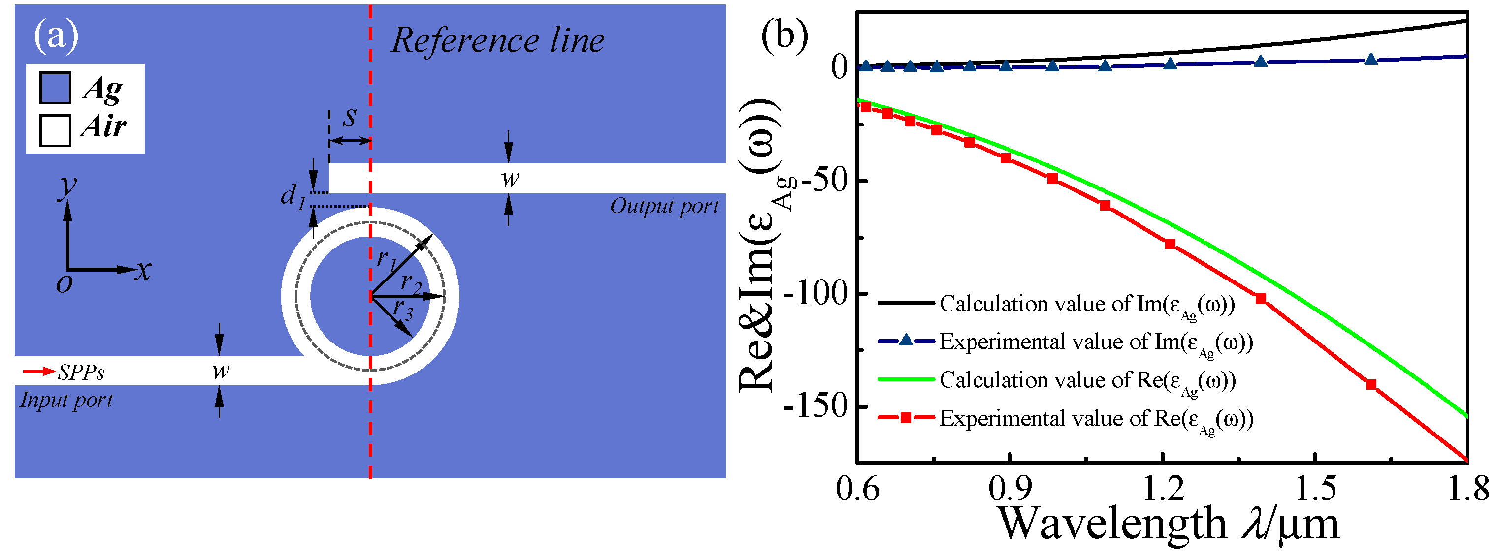
2. Structure Model and Analytical Method

As shown in Figure 1a, the 2D schematic of the proposed plasmonic structure is composed of a whistle-shaped cavity and an MIM waveguide. The whistle-shaped cavity was composed of the input MIM waveguide on-interval and a ring cavity. As shown in Figure 1, the blue and white parts denote Ag (εm) and air (εs), respectively. The widths w of these MIM waveguides were fixed at 50 nm to support the only fundamental transverse magnetic (TM0) in the MIM waveguides. The length of the output MIM waveguide is L, and the gap between the output MIM waveguide and the ring cavity is d1. The inner and outer radii of the ring cavity in the whistle-shaped structure are represented by r1 and r3, and the center radius of the ring cavity is r2 = (r1 + r3)/2. The red vertical dashed line passes through the center of the ring cavity and is defined as the reference line.
The frequency-dependent complex relative permittivity ε(ϖ) of silver is characterized by the modified Debye–Drude dispersion mode [36,37] as follows:
ε ( ϖ ) = ε + ( ε s ε ) 1 + i ϖ τ + σ i ϖ ε 0
where ε = 3.8344 is the infinite frequency permittivity, εs = −9530.5 represents the static permittivity, σ = 1.1486 × 10⁷ S/m is the conductivity, and τ = 7.35 × 10⁻¹⁵ s is the relaxation time. Figure 1b shows the real part and the image part of the experiment value and modified value using the Debye–Drude model for the silver relative permittivity. The theory mode is in good agreement with the experimental data.
The transmission properties of the single whistle-shaped structure and the double whistle-shaped coupled derived structure were investigated using FEM with perfectly matched layer-absorbing boundary conditions. The transmittance is defined as T = |S21|2, where S21 is the transmittance of the MIM waveguide [38].
For MIM waveguides, only the fundamental transverse magnetic (TM0) mode can be supported, and its dispersion relation is expressed as [39]:
tanh(κw) = −2κpα/(κ2 + p2α2)
where κ and w are the perpendicular core wave vector and the insulator width of the MIM waveguide, respectively. The symbols in Equation (1) are defined as p = εin/εm and α = [k02(εinεm) + κ]1/2, where εin and εm are the dielectric constants of the insulator and the metal, respectively; k0 = 2π/λ0 is the free space wave vector; κ can be solved from Equation (1) using the iterative method. Thus, the effective index neff of the MIM waveguide can be defined as neff = (εm + (κ/k0)2)1/2. The wavelength of SPPs, λspp, can be expressed as λspp = λ0/Re (neff), where Re (neff) is the real part of neff.

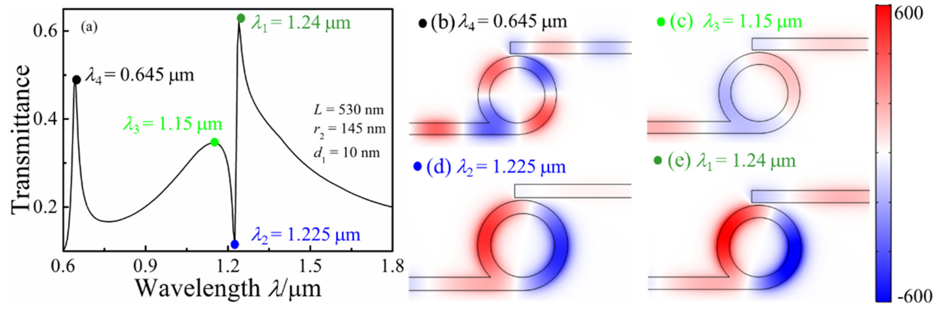
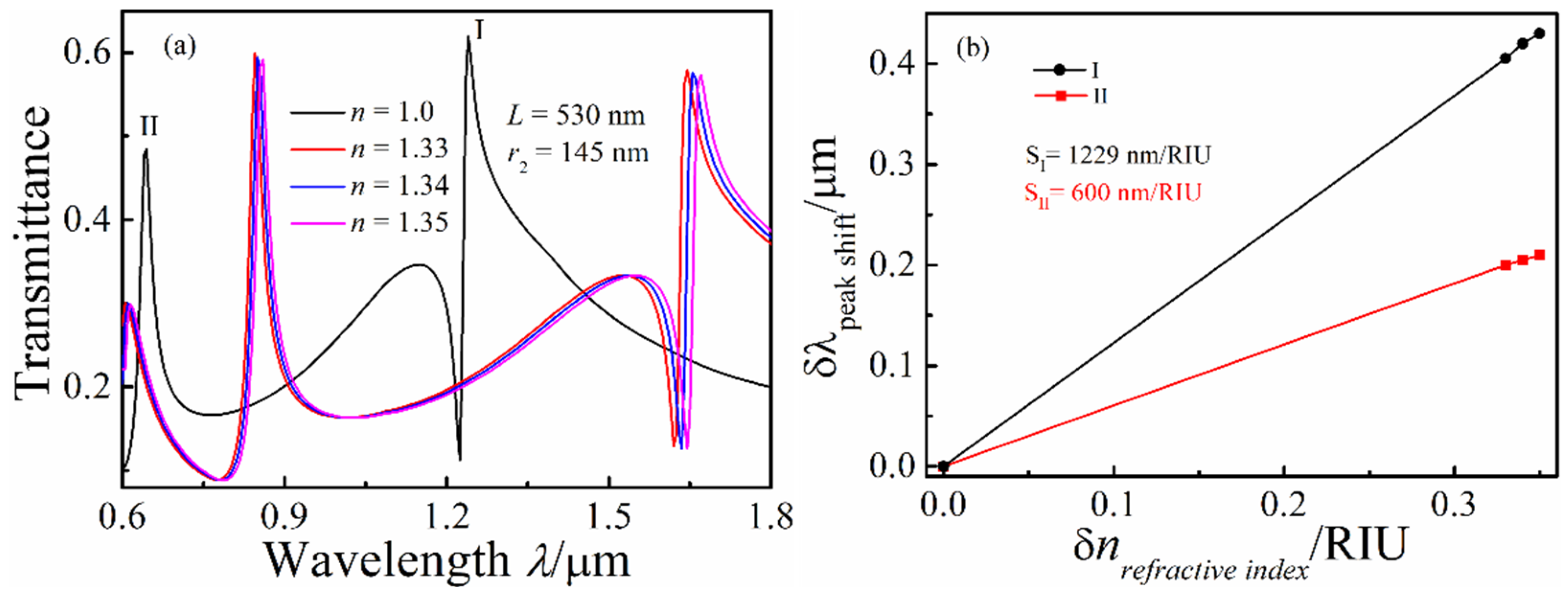
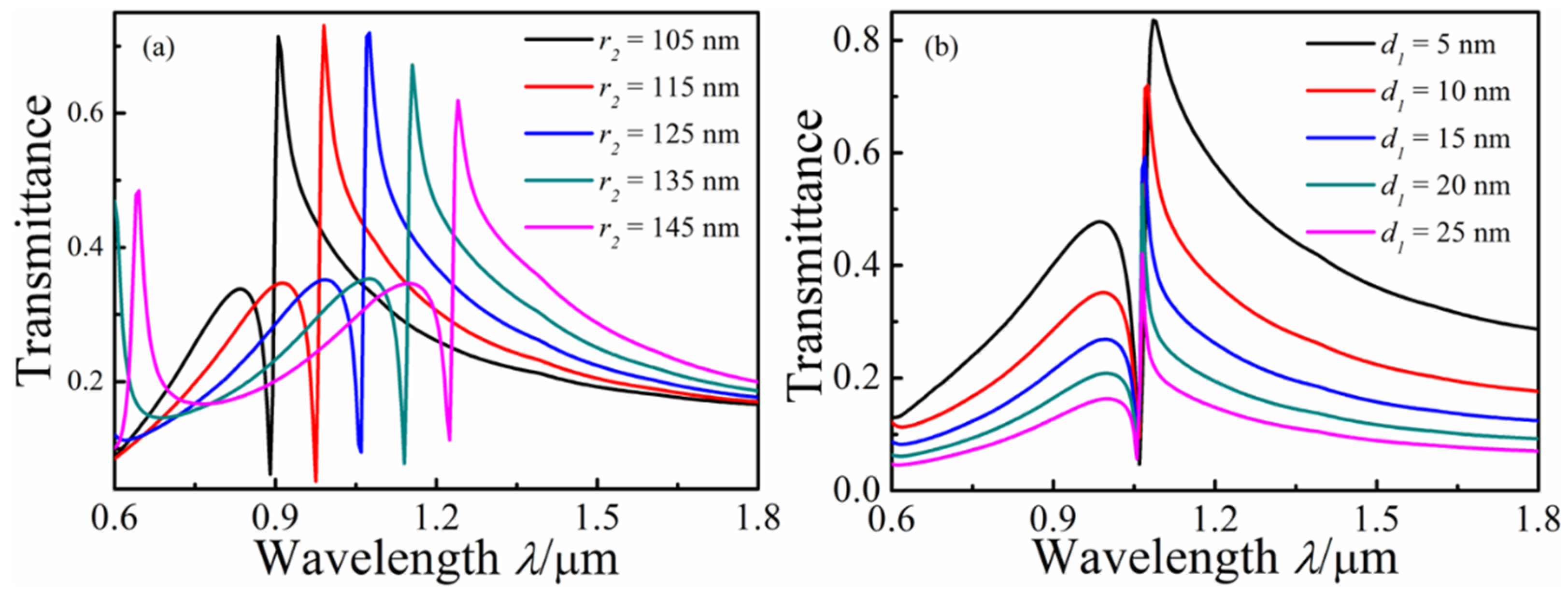
3. Results and Discussions

Figure 2a shows the transmission spectrum of the whistle-shaped MIM waveguide system with s = 30 nm, w = 50 nm, d = 10 nm, and r2 = 145 nm. As shown in Figure 2a, three asymmetrical profile peaks (0.645, 1.15, and 1.24 μm) can be observed in the transmission spectrum, which are regarded as the Fano resonance. The transmittance shows an unusual variation with the increase in wavelength from 1.15 to 1.24 μm; in particular, a steep slope curve can be observed in the transmission spectrum at the range of 1.225–1.24 μm. The Hz field distributions at λ = 0.645, 1.15, 1.225, and 1.24 mm were simulated and are displayed in Figure 2b–e to understand the physical mechanism of the asymmetrical profile peaks of the proposed structure. Steady stand wave modes can be observed, and the black arrows represent the time-average power flow distributions in the Hz field distribution graphs. For λ = 0.645 μm, Re(neff) = 1.4435, and λspp = 0.4468 μm, so the number of wave nodes can be calculated by 2πr2/λspp = 2. As shown in Figure 2b, two wave nodes were formed in the Hz field distribution, and the time-average power flow distributions show an anticlockwise mode in the ring cavity. Most of the SPPs’ energy was limited in the whistle-shaped cavity, and part of the SPPs’ energy was coupled into the output waveguide, so a peak was formed in the transmission spectrum, as shown in Figure 2a. For λ = 1.24 μm, the Fano resonance was caused by the interference between the anticlockwise mode and the clockwise mode. The Hz field distribution (Figure 2e) is similar to Figure 2d (λ2 = 1.225 μm), but the SPPs’ energy could be coupled into the output waveguide and a resonance peak is formed in the transmission spectrum for λ1 = 1.24 μm. For λ2 = 1.225 μm, the SPPs’ energy was not coupled into the output waveguide. The time-average power flows show that an anticlockwise mode occurred. For λ3 = 1.15 μm, the Hz field distribution was mainly distributed in the whistle-shaped cavity, and part of SPPs was coupled into the output waveguide. The time-average power flows show a clockwise mode. Thus, the Fano resonance was due to the coupling between the anticlockwise and clockwise modes. For λ4 = 0.645 μm, the Hz field distribution reveals that a second-order vibration mode was formed in the whistle-shaped cavity, which was a new vibration mode. The time-average power flows show an anticlockwise mode.
The transmission spectra were simulated by replacing the air of the MIM waveguide system with different refractive index media (n = 1, 1.33, 1.34, and 1.35), which are shown in Figure 3a, to investigate the effect of refractive index n on the transmission properties of the whistle-shaped MIM waveguide system. As shown in Figure 3a, the Fano resonance peak red shifted with the increase in n, and another new resonance peak can be observed at the short wavelength range when n was larger than 1.33. The radius r2 of the whistle-shaped cavity was fixed because the neff value in the MIM waveguide-coupled whistle-shaped cavity decreased with the increase in n, and the number of modes increased. Therefore, a peak can be observed at the near short wave (0.60–0.7 μm) in the transmission spectra. We calculated the shift of the Fano resonance peaks (I and II) with the refractive index change. The sensitivity fitting curves of peaks I and II are shown in Figure 3b. The sensitivity of peak I is S1 = δλn = 600 nm/RIU, and the sensitivity of peak II is S2 = δλn = 1229 nm/RIU.
r1 was varied from 130 to 170 nm at intervals of 10 nm with n = 1, w = 50 nm, and L = 530 nm to study the effect of the different radii of the ring cavity on the Fano resonance of the MIM waveguide. With the increasing radius r2 of the ring cavity, red shifts of the transmission spectrum and decreases in the transmittances of the Fano resonance peak can be observed in Figure 4a. Figure 4b shows the transmission spectrum with different coupled distances d between the top waveguide and the whistle-shaped ring cavity, and the other parameters were fixed as n = 1, r1 = 150 nm, r3 = 100 nm, and d1 = 10 nm. From the transmission spectrum, the Fano resonance peak appears to be blue-shifted, but this was actually caused by the Fano resonance peak widening as d1 increased, and the transmittances decreased with the increase in d1. In contrast, the Fano resonance valley hardly shifted with as d1 increased, which was dependent on the length of the whistle-shaped ring cavity.
In this section, we investigate the derivative structure, MIM waveguide-coupled whistle-shaped cavity, and the proposed structure, as shown in Figure 5a. Figure 5b shows the transmission spectrum of the proposed MIM waveguide-coupled double whistle-shaped cavity, and the structural parameters were fixed at n = 1, R2 = r2 = 125 nm, and d2 = 10 nm. Although the transmission spectrum is similar to the MIM waveguide-coupled single-whisper cavity, another new peak emerged in the transmission spectrum. FR2 was unremarkable and FR1 and FR2 were extremely close when R2 = r2. The Hz field distributions at λ1 = 1.09 mm, λ2 = 1.06 mm, λ3 = 1.05 mm, λ4 = 1.045 mm, and λ5 = 0.995 mm are displayed in Figure 5c. For λ1 = 1.09 mm, the phase of the Hz field distribution in the bottom and top whistle-shaped cavities was opposite, and the output waveguide was located at the position of the strong negative time-averaged power flow, so the SPPs’ energy could be passed from the output waveguide. For λ2 = 1.06 mm, the Hz field distribution in the bottom and top whistle-shaped cavities was symmetric on the vertical axis. The output waveguide was located at the position joint between the positive and negative time-averaged power flows, so few SPPs’ energy could be passed. For λ3 = 1.05 mm, the strong Hz field distribution concentrated in the bottom whistle-shaped cavity, and few SPPs’ energy were coupled into the top whistle-shaped cavity. The output waveguide was located in the abdominal of the negative time-averaged power flow, so the SPPs’ energy could be passed to the output waveguide. For λ4 = 1.045 mm, the Hz field distribution in the bottom and top whistle-shaped cavities was located on the horizontal axis. For λ5 = 0.995 mm, the strong Hz field was mainly distributed in the bottom whistle-shaped cavity, and few SPPs’ energy were coupled into the top whistle-shaped cavity.
The value of R2 changed and was varied from 130 to 170 nm at intervals of 10 nm, with r1 = 150 nm and d2 = 10 nm, to further investigate the effect of the top whisper cavity on the Fano resonance. A remarkable double Fano resonance was found in the transmission spectra, as shown in Figure 6a. With the increase in R2, an obvious red shift can be observed in the transmission spectra. The locations of the FR2 peak’s red shift with the increase in R2 and the transmittance of FR2 first showed decreases and then increases. When R2 = r2, the transmittance was minimal, and with an increasing R2, new FR3 peaks can be observed in the transmission spectra for R2 = 135 nm. From Figure 6b, FR1 seems to be blue-shifted, but this was actually due to a decrease in the peak width of FR1 with the increase in the distance (d2) between the ring cavity from 5 to 25 nm when the values of R2 and r2 were fixed as 125 nm. The transmittance of FR2 decreased, but FR2 experienced no shift with as d2 increased. When d2 = 25 nm, the peak of FR2 disappeared in the transmission spectra. With an increasing d2, FR3 was blue-shifted and the transmittance decreased. Figure 6c shows the transmittance spectrum when changing its refractive index n (n = 1, 1.33, 1.34, and 1.35) of the proposed double whisper cavities, and the other parameters were fixed as d2 = 10 nm, r2 = 125 nm, and R2 = 115 nm. The Fano resonance exhibited a red shift with the increase in the refractive index n, and the sensitivities of 1.057 μm/RIU and 0.969 μm/RIU were obtained at λ1(FR1) and λ2(FR2).

4. Conclusions

In this work, a plasmonic refractive index sensor based on Fano resonance was proposed. The transmission properties were simulated numerically using FEM. Fano resonance was realized in the MIM waveguide-coupled whistle-shaped cavity. This phenomenon is due to the coupling of SPPs in the whistle-shaped cavity between the transmission along the clockwise and anticlockwise directions. Refractive index-sensing based on the Fano resonance was investigated by changing the refractive index of the insulator of the MIM waveguide. The results showed that a maximum sensitivity of 1229 RIU/nm was obtained. Compared to the single MIM waveguide-coupled whistle-shaped cavity, the double MIM with whistle-shaped cavity structure exhibited multi-Fano resonance. The refractive index sensor’s sensitivity was smaller than that of the single MIM waveguide-coupled whistle-shaped cavity. The results of this study will help in the design of new photonic devices and microsensors with high sensitivity.

Author Contributions

Conceptualization, Z.Z. and B.L.; methodology, X.Z. (Xiaolong Zhao); software, H.S.; validation, Y.L. investigation, J.Z.; data curation, B.L. and H.Z.; writing—original draft preparation, B.L. and H.S.; writing—review and editing, Z.Z., X.Z. (Xupeng Zhu) and X.C. All authors have read and agreed to the published version of the manuscript.

Funding

This work was funded by the Key Research and Development Program of Shanxi Province (No. 202102030201008), the National Natural Science Foundation of China (No. 12004150), the Fundamental Research Program of Shanxi Province (No. 201901D111148), and the Scientific and Technological Innovation Programs of Higher Education Institutions in Shanxi (No. 2020L0275).

Data Availability Statement

The data presented in this study are available upon request from the corresponding author. The data are not publicly available due to being supplied by Key Laboratory of Instrumentation Science & Dynamic Measurement (North University of China), Ministry of Education, and so cannot be made freely available.

Conflicts of Interest

The authors declare no conflict of interest.

References

  1. Barnes, W.L.; Dereux, A.; Ebbesen, T.W. Surface plasmon subwavelength optics. Nature 2003, 424, 824–830. [Google Scholar] [CrossRef] [PubMed]
  2. Ozbay, E. Plasmonics: Merging Photonics and Electronics at Nanoscale Dimensions. Science 2006, 311, 189–193. [Google Scholar] [CrossRef] [PubMed]
  3. Fang, Y.; Sun, M. Nanoplasmonic waveguides: Towards applications in integrated nanophotonic circuits. Light-Sci. Appl. 2015, 4, e294. [Google Scholar] [CrossRef]
  4. Chen, J.; Sun, C.; Rong, K.; Li, H.; Gong, Q. Polarization-free directional coupling of surface plasmon polaritons. Light-Sci. Appl. 2015, 9, 419–426. [Google Scholar] [CrossRef]
  5. Zhang, X.; Liu, Z. Superlenses to overcome the diffraction limit. Nat. Mater. 2008, 7, 435–441. [Google Scholar] [CrossRef] [PubMed]
  6. Green, M.A.; Pillai, S. Harnessing plasmonics for solar cells. Nat. Photonics 2012, 6, 130–132. [Google Scholar] [CrossRef]
  7. Zhou, F.; Qin, F.; Yi, Z.; Yao, W.T.; Liu, Z.; Wu, X.; Wu, P. Ultra-wideband and wide-angle perfect solar energy absorber based on Ti nanorings surface plasmon resonance. Phys. Chem. Chem. Phys. 2021, 23, 17041–17048. [Google Scholar] [CrossRef]
  8. Zhao, F.; Lin, J.; Lei, Z.; Yi, Z.; Qin, F.; Zhang, J.; Liu, L.; Wu, X.; Yang, W.; Wu, P. Realization of 18.97% theoretical efficiency of 0.9 µm Thick c-Si/ZnO Heterojunction Ultrathin-film Solar Cells via Surface Plasmon Resonance Enhancement. Phys. Chem. Chem. Phys. 2022, 24, 4871–4880. [Google Scholar] [CrossRef]
  9. Joo, Y.H.; Song, S.H.; Magnusson, R. Demonstration of long-range surface plasmon-polariton waveguide sensors with asymmetric double-electrode structures. Appl. Phys. Lett. 2010, 97, 201105. [Google Scholar] [CrossRef]
  10. Zhao, L.; Zhang, X.; Wang, J.; Yu, W.H.; Li, J.D.; Su, H.; Shen, X.P. A Novel Broadband Band-pass Filter Based on Spoof Surface Plasmon Polaritons. Sci. Rep. 2016, 6, 36069. [Google Scholar] [CrossRef]
  11. Zaky, Z.A.; Singh, M.R.; Aly, A.H. Tamm resonance excited by different metals/graphene. Photonic. Nanostruct. 2022, 49, 100995. [Google Scholar] [CrossRef]
  12. Zaky, Z.A.; Singh, M.R.; Aly, A.H. Tamm Plasmon Polariton as Refractive Index Sensor Excited by Gyroid Metals/Porous Ta2O5 Photonic Crystal. Plasmonics 2022, 17, 681–691. [Google Scholar] [CrossRef]
  13. Li, L.; Hao, H.Y. Evolution of high-order Tamm plasmon modes with a metal-PhC cavity. Sci. Rep. 2022, 12, 14921. [Google Scholar] [CrossRef] [PubMed]
  14. Han, Z. Ultracompact plasmonic racetrack resonators in metal-insulator-metal waveguides. Photonic. Nanostruct. 2010, 8, 172–176. [Google Scholar] [CrossRef]
  15. Makarenko, K.S.; Hoang, T.X.; Duffin, T.J.; Radulescu, A.; Kalathingal, V.; Lezec, H.J.; Chu, H.S.; Nijhuis, C.A. Efficient Surface Plasmon Polariton Excitation and Control over Outcoupling Mechanisms in Metal–Insulator–Metal Tunneling Junctions. Adv. Sci. 2020, 7, 1900291. [Google Scholar] [CrossRef]
  16. Kozma, P.; Kehl, F.; Ehrentreich-Forster, E.; Stamm, C.; Bier, F.F. Integrated planar optical waveguide interferometer biosensors: A comparative review. Biosens. Bioelectron. 2014, 58, 287–307. [Google Scholar] [CrossRef]
  17. Tian, M.; Lu, P.; Chen, L.; Liu, D.M.; Lv, C. All-optical switching in MIM waveguide resonator with an outer portion smooth bend structure containing nonlinear optical materials. Opt. Commun. 2012, 285, 4562–4566. [Google Scholar] [CrossRef]
  18. Pang, S.F.; Huo, Y.P.; Xie, Y.; Hao, L.M. Fano resonance in MIM waveguide structure with oblique rectangular cavity and its application in sensor. Opt. Commun. 2016, 381, 409–413. [Google Scholar] [CrossRef]
  19. Wang, G.X.; Lu, H.; Liu, X.M. Dispersionless slow light in MIM waveguide based on a plasmonic analogue of electromagnetically induced transparency. Opt Express 2012, 20, 20902–20907. [Google Scholar] [CrossRef]
  20. Wen, K.H.; Hu, Y.H.; Chen, L.; Zhou, J.Y.; He, M.; Lei, L.; Meng, Z.M.; Wu, Y.J.; Li, J.F. Fano Resonance Based on End-Coupled Cascaded-Ring MIM Waveguides Structure. Plasmonics 2017, 12, 1875–1880. [Google Scholar] [CrossRef]
  21. Yun, B.F.; Zhang, R.H.; Hu, G.H.; Cui, Y.P. Ultra Sharp Fano Resonances Induced by Coupling between Plasmonic Stub and Circular Cavity Resonators. Plasmonics 2016, 11, 1157–1162. [Google Scholar]
  22. Fano, U. Effects of configuration interaction on intensities and phase shifts. Phys. Rev. 1961, 124, 1866–1878. [Google Scholar] [CrossRef]
  23. Khanikaev, A.B.; Wu, C.H.; Shvets, G. Fano-resonant metamaterials and their applications. Nanophotonics 2013, 2, 247–264. [Google Scholar] [CrossRef]
  24. Limonov, M.F.; Rybin, M.V.; Poddubny, A.N.; Kivshar, Y.S. Fano resonances in photonics. Nat. Photonics 2017, 11, 543–554. [Google Scholar] [CrossRef]
  25. Stern, L.; Grajower, M.; Levy, U. Fano resonances and all-optical switching in a resonantly coupled plasmonic–atomic system. Nat. Commun. 2014, 5, 4865. [Google Scholar] [CrossRef]
  26. Deng, Z.L.; Dong, J.W. Lasing in plasmon-induced transparency nanocavity. Opt. Express 2013, 21, 20291–20302. [Google Scholar] [CrossRef]
  27. Wu, C.H.; Khanikaev, A.B.; Adato, R.; Arju, N.; Yanik, A.A.; Altug, H.; Shvets, G. Fano-resonant asymmetric metamaterials for ultrasensitive spectroscopy and identification of molecular monolayers. Nat. Mater. 2012, 11, 69–75. [Google Scholar] [CrossRef]
  28. Wu, C.H.; Khanikaev, A.B.; Shvets, G. Broadband Slow Light Metamaterial Based on a Double-Continuum Fano Resonance. Phys. Rev. Lett. 2011, 106, 107403. [Google Scholar] [CrossRef]
  29. Zhang, F.; Hu, X.Y.; Zhu, Y.; Yang, H.; Gong, Q.H. Ultralow-power all-optical tunable dual Fano resonances in nonlinear metamaterials. Appl. Phys. Lett. 2013, 103, 191116. [Google Scholar] [CrossRef]
  30. Deng, Y.; Cao, G.T.; Yang, H. Tunable Fano resonance and high-sensitivity sensor with high figure of merit in plasmonic coupled cavities. Photonic. Nanostruct. 2018, 28, 45–51. [Google Scholar] [CrossRef]
  31. Zhang, Y.J.; Kuang, Y.Q.; Zhang, Z.D.; Tang, Y.; Han, J.Q.; Wang, R.B.; Cui, J.G.; Hou, Y.L.; Liu, W.Y. High-sensitivity refractive index sensors based on Fano resonance in the plasmonic system of splitting ring cavity-coupled MIM waveguide with tooth cavity. App. Phys. A 2019, 125, 13. [Google Scholar] [CrossRef]
  32. Lotfiani, A.; Mohseni, S.M.; Ghanaatshoar, M. High-sensitive optoelectronic SPR biosensor based on Fano resonance in the integrated MIM junction and optical layers. Opt. Commun. 2020, 477, 126323. [Google Scholar] [CrossRef]
  33. Deng, Y.; Cao, G.T.; Yang, H.; Li, G.H.; Chen, X.S.; Lu, W. Tunable and high-sensitivity sensing based on Fano resonance with coupled plasmonic cavities. Sci. Rep. 2017, 7, 10639. [Google Scholar] [CrossRef] [PubMed]
  34. Lan, G.Q.; Liu, S.G.; Ma, Y.; Zhang, X.R.; Wang, Y.X.; Song, Y.L. Sensitivity and figure-of-merit enhancements of liquid-prism SPR sensor in the angular interrogation. Opt. Commun. 2015, 352, 49–54. [Google Scholar] [CrossRef]
  35. Chen, H.; Chen, Z.; Yang, H.; Wen, L.; Yi, Z.; Zhou, Z.; Dai, B.; Zhang, J.; Wu, X.; Wu, P. Multi-mode surface plasmon resonance absorber based on dart-type single-layer graphene. RSC Adv. 2022, 12, 7821–7829. [Google Scholar] [CrossRef] [PubMed]
  36. Zayats, A.V.; Smolyaninov, I.I.; Maradudin, A.A. Nano-optics of surface plasmon polaritons. Phys. Rep. 2005, 408, 131–314. [Google Scholar] [CrossRef]
  37. Gai, H.; Wang, J.; Tian, Q. Modified Debye model parameters of metals applicable for broadband calculations. Appl. Opt. 2007, 46, 2229–2233. [Google Scholar] [CrossRef]
  38. Zhang, Z.D.; Luo, L.; Xue, C.Y.; Zhang, W.D.; Yan, S.B. Fano Resonance Based on Metal-Insulator-Metal Waveguide-Coupled Double Rectangular Cavities for Plasmonic Nanosensors. Sensors 2016, 16, 642. [Google Scholar] [CrossRef]
  39. Zhang, Z.Y.; Wang, J.D.; Zhao, Y.A.; Lu, D.; Xiong, Z.H. Numerical investigation of a branch-shaped filter based on metal-insulator-metal waveguide. Plasmonics 2011, 6, 773. [Google Scholar] [CrossRef]
Figure 1. (a) Two-dimensional schematic for the MIM waveguides coupled with a whistle-shaped cavity. (b) The calculated and experimental values of the real and imaginary parts of the permittivity of silver.
Micromachines 13 01592 g001
Figure 2. (a) Transmission spectra of the MIM waveguide-coupled whistle-shaped cavity; (b) contour profiles of the normalized Hz field distributions of the MIM waveguide whistle-shaped cavity: (b) λ = 0.645 mm, (c) λ = 1.15 mm, (d) λ = 1.225 mm, and (e) λ = 1.24 mm.
Micromachines 13 01592 g002
Figure 3. (a) Transmission spectra of the MIM waveguide-coupled whistle-shaped cavity with changing n; (b) shift of the Fano resonance peak as a function of the refractive index change δn.
Micromachines 13 01592 g003
Figure 4. Transmission spectra of the MIM waveguide-coupled whistle-shaped cavity: (a) With changing r2; (b) with changing d1.
Micromachines 13 01592 g004
Figure 5. (a) Schematic of the MIM waveguide-coupled double whisper cavities; (b) transmission spectrum of the double whisper cavity structure; (c) Hz field distribution at different resonance wavelengths.
Micromachines 13 01592 g005
Figure 6. Transmission spectra of the different structural parameters at the MIM waveguide-coupled double whistle-shaped cavities: (a) R2 changing; (b) d2 changing; (c) n changing; (d) sensitivity.
Micromachines 13 01592 g006
Publisher’s Note: MDPI stays neutral with regard to jurisdictional claims in published maps and institutional affiliations.

