Article

A Magnetic-Coupled Nonlinear Electromagnetic Generator with Both Wideband and High-Power Performance

1
Jiangsu Provincial Key Laboratory of Advanced Robotics, School of Mechanical and Electric Engineering, Soochow University, Suzhou 215123, China
2
Harbin Institute of Technology, School of Mechatronics Engineering, Harbin 215123, China
*
Author to whom correspondence should be addressed.
Micromachines 2021, 12(8), 912; https://doi.org/10.3390/mi12080912
Submission received: 4 June 2021 / Revised: 17 July 2021 / Accepted: 20 July 2021 / Published: 30 July 2021
(This article belongs to the Special Issue Energy Harvesters and Self-powered Sensors for Smart Electronics)

Abstract

:
This paper proposed a high-performance magnetic-coupled nonlinear electromagnetic generator (MNL-EMG). A high-permeability iron core is incorporated to the coil. The strong coupling between the iron core and the vibrating magnets lead to significantly improved output power and a broadened operating bandwidth. The magnetic force of the iron core to the permanent magnets and the magnetic flux density inside the iron core are simulated, and the dimension parameters of the MNL-EMG are optimized. Under acceleration of 1.5 g, the MNL-EMG can maintain high output performance in a wide frequency range of 17~30 Hz, which is 4.3 times wider than that of linear electromagnetic generator (EMG) without an iron core. The maximum output power of MNL-EMG reaches 174 mW under the optimal load of 35 Ω, which is higher than those of most vibration generators with frequency less than 30 Hz. The maximum 360 parallel-connected LEDs were successfully lit by the prototype. Moreover, the prototype has an excellent charging performance such that a 1.2 V, 900 mAh Ni-MH battery was charged from 0.95 V to 0.98 V in 240 s. Both the simulation and experiments verify that the proposed bistable EMG device based on magnetic coupling has advantages of wide operating bandwidth and high output power, which could be sufficient to power micro electronic devices.

1. Introduction

With the maturity of low-power wireless transmission technology, various types of micro sensors, embedded systems, and wireless sensor networks have been developed rapidly [1]. The power consumption of micro electronic devices has been reduced to the order of microwatts. Due to the short service life, limited stored energy and environmental pollution problems, traditional chemical batteries are not suitable for the power supply of microelectronic devices with complex application environments [2,3,4].
Vibration energy harvesting technology converts vibration energy into electrical energy through electromechanical conversion mechanisms such as electromagnetic [5,6,7,8], piezoelectric [9,10,11,12,13], electrostatic [14,15,16], and triboelectric [17,18,19,20]. Among them, piezoelectric generators (PEGs) are especially attractive due to their simple construction, compact size, high power density and easy manufacturability, and PEGs are widely used in low-power electronic devices such as embedded systems and wireless sensing network nodes. Kim et al. [21] developed a flexible P(VDF-TrEE) film-based PEG on PDMS substrate with high power density, and the demonstrated output voltage, current, and power density were 5.8 V, 3.2 μA, and 6.62 mW/cm3, respectively. Triboelectric nanogenerators (TENG), on the other hand, have attracted extensive attention and research because of its high output voltage, simple fabrication, low cost, and wide application of materials [22]. Han et al. [23] presented an r-shaped hybrid piezo/triboelectric nanogenerator to enhance the output performance. With a 5 Hz periodic external force, the output voltage, current, and power density of the triboelectric part were 240 V, 27.2 μA, and 2.04 mW/cm3. Ma et al. [24] designed and investigated an integrated electromagnetic-triboelectric-piezoelectric hybrid generator. The tested short-circuit currents of electromagnetic generator (EMG), TENG, and PEG are 21 mA, 4.1 μA, and 0.7 μA. Furthermore, the maximum instantaneous output powers of EMG, TENG, and PEG are 30.9 mW, 712.3 μW, and 6.37 μW, respectively, under the respective external load resistances of 200 Ω, 70 MΩ, and 50 MΩ. Therefore, compared with PEG and TENG, EMG has the advantages of low impedance and high current output, and the output power can meet special requirements.
At present, most of the vibration generators are linear designs, which can achieve the maximum output power only when the resonance is consistent with the external vibration source [25]. Once the frequency of the vibration source deviates from the resonance of the generator, the output power will decrease rapidly, indicating a relatively narrow working bandwidth [26]. In general, the environmental vibration sources are random and cover a certain range, the working frequency of the vibration generators need to be broadened to achieve high output performance. To increase the output power and broaden the operating bandwidth of the vibration generators, various approaches, such as oscillator arrays [27], multi-modal oscillators [28,29], and active or passive frequency tuning technologies [30] have been proposed. In addition, researchers have exploited numerous approaches to introduce nonlinearity into vibration generators, including monostable Duffing oscillators [31,32], bistable oscillators [33,34,35], and frequency-up-conversion technologies [36,37] etc. The above mechanisms are commonly used in PEGs, EMGs, and TENGs. Stanton et al. [38] designed a bistable broadband PEG by adding a pair of repulsive magnets to a PZT cantilever. Bouhedma et al. [39] proposed a dual-frequency PEG with integrated magnets in a folded beam resonant structure. A bidirectional frequency tuning is achieved by adjusting the position of the magnet, which greatly broadens the operating bandwidth of the system. Magnetic spring is the most investigated structure among nonlinear EMGs. A traditional magnetic spring-based generator consists of two (top and bottom) fixed magnets with a third magnet levitated between them [40]. Mann et al. [41] proposed a Duffing electromagnet oscillator that uses magnetic levitation to realize resonance tuning and bandwidth broadening. Chen et al. [42] modelled and fabricated a multi-degree of freedom EMG using vertical linear springs and nonlinear magnetic springs based on magnetic levitation. In addition to magnetic spring structure, a double-clamped beam structure with strong natural nonlinearity is also an effective method to broaden the frequency bandwidth. Lu et al. [43] proposed a nonlinear electromagnetic vibration energy harvester with a monostable double-clamp beam, and the average power and frequency bandwidth of the harvester reached 1.78 mW and 11 Hz, respectively, at 1 g acceleration.
Although the bandwidth of EMGs can be broadened in several ways, most of them use air as the magnetic induction line transfer medium between the magnet and the coil, which leads to weak magnetic coupling because of the low magnetic permeability of air. When soft magnetic materials with high permeability are introduced into electromagnetic energy harvesting applications, it leads to significant enhancement in output voltage and power density compared to energy harvesters based on air-cored coils [44]. Soft magnetic materials with high magnetic permeability can be used either as flexible cantilevers in oscillating structures [45] or as fixed elements in coils [46]. However, soft magnetic materials as oscillating structures may induce high stiffness, and in this case low resonant frequencies cannot be achieved. In contrast, placing the soft magnetic material statically in the coil can significantly increase the power density by the strong magnetic coupling between the fixed high-permeability soft magnetic material and the oscillating permanent magnet pair. Sun et al. [44] designed an EMG using a pair of antiparallel permanent magnets as the vibrating part and a soft magnetic material with high permeability as the static part in the coil, which combine to form a closed magnetic circuit and make the coupling force between the permanent magnets and the soft magnetic material nonlinear by adjusting the spacing. This EMG can simultaneously increase the output power and operating bandwidth.
In this work, a simple but effective approach to realize the nonlinear EMG with both wide bandwidth and high power based on magnetic coupling between the magnets and iron core is presented. A high-permeability soft magnetic material is placed in the center of the coil as a permeable core, and the strong nonlinear magnetic coupling between the oscillating magnet and the core enhances the magnetic flux inside the coil, thus increasing the output power. Its design, mathematical model, and simulation methods can be beneficial to the research of other EMGs, which is the contribution of this paper. The structure design and working principle are described and the equivalent dynamical model is developed in Section 2. Simulation and parameter optimization are provided in Section 3. Experimental setup and detailed tests are described in Section 4, together with discussion of test results and comparison to other low-frequency vibration generators reported in recent literatures.

2. Device Design and Theoretical Analysis

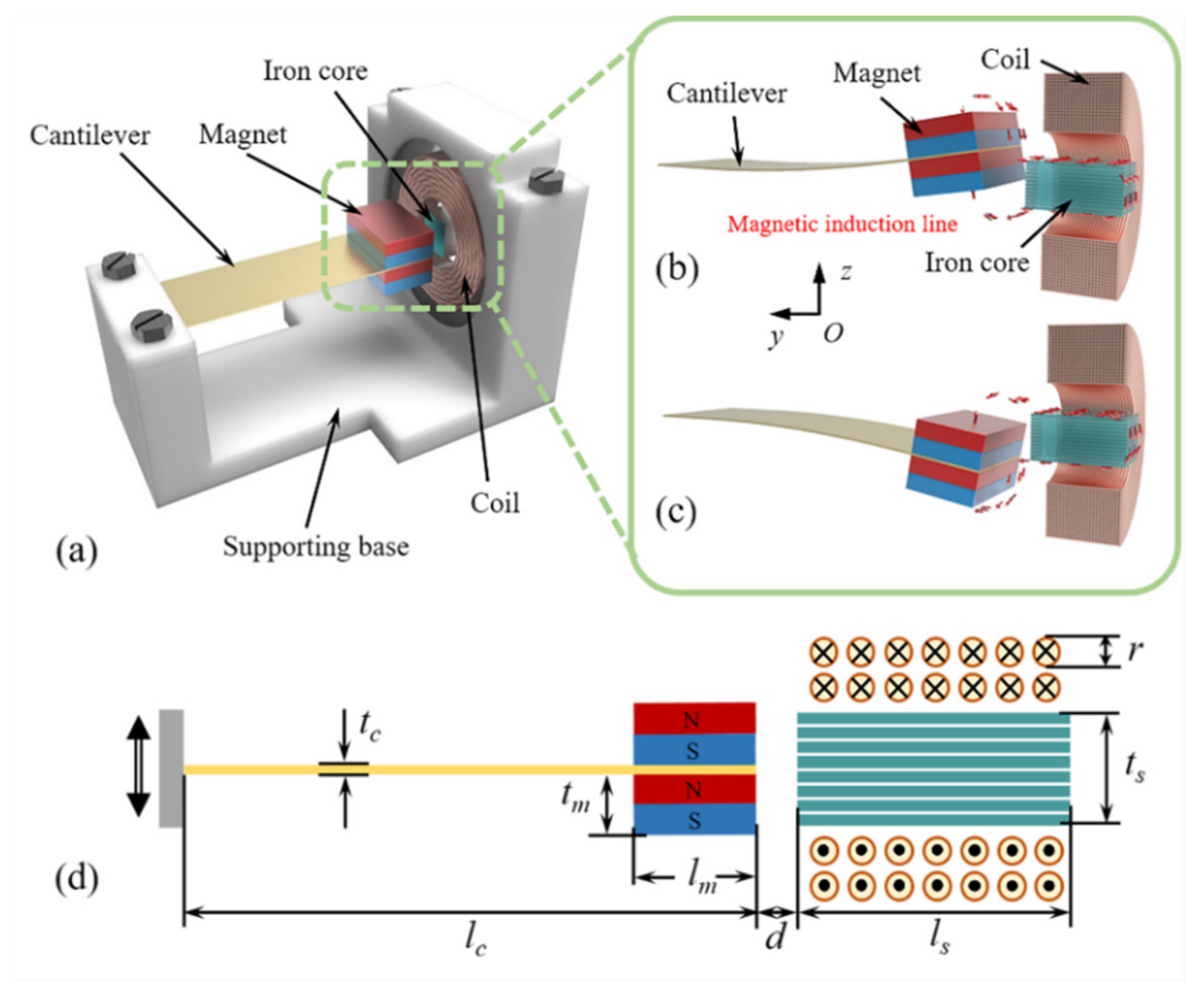
Structural Design and Working Principle

The structure of the proposed magnetic-coupled nonlinear electromagnetic generator (MNL-EMG) is shown in Figure 1a. The MNL-EMG consists of a supporting base, a cantilever beam with two NdFeB magnets fixed at the free end, and a winding coil around a laminated iron core with high permeability. The material of the iron core is silicon lamination, which has 3% silicon content, which can increase the resistivity and maximum permeability of iron and reduce the core loss. The winding coil is wound with a diameter of 0.3 mm and a turn count of 500. The cantilever beam is made of phosphor bronze with good elasticity and non-magnetism. When the cantilever beam drives the end magnets to vibrate up and down, the iron core attracts the surrounding magnetic induction lines through the center of the coil. Therefore, the magnetic flux penetrating the coil changes, and an induced voltage will be generated across the coil. The magnetic force between the magnets and iron core varies nonlinearly with the displacement of the magnets. Hence the stiffness of the cantilever beam changes nonlinearly, resulting in the widening effect of operating bandwidth. Compared with the nonlinear EMGs relied on repulsion or attraction between magnets, this MNL-EMG based on the nonlinear attraction between the magnet and iron core has advantages of increasing the electromagnetic output power using a high-permeability iron core. Figure 1b,c shows the distribution of magnetic induction lines around the magnets and iron core when the magnets are above or below the iron core. The magnetic induction lines start from the N pole of the magnets, flow into the iron core, and then flow back to the S pole of the magnets. The iron core with high permeability can concentrate the magnetic induction lines inside the coil, enable the direction of magnetic induction lines perpendicular to the coil plane, greatly increases the magnetic flux, therefore increasing the induced voltage of the coil. The schematic diagram of the MNL-EMG is shown in Figure 1d, and the geometric parameters are listed in Table 1.
An equivalent mass-spring-damper model of the MNL-EMG is developed as shown in Figure 2a. The corresponding dynamic equation can be expressed as:
m e q Z ( t ) + c e q Z ( t ) + k e q Z ( t ) = m e q u ( t ) F z ( Z ) F e ( Z ) ,
where meq, ceq, and keq represent the equivalent mass, equivalent damping, and equivalent stiffness of the cantilever beam, respectively; Z is the vertical displacement of the magnets at the free end of the cantilever beam; u(t) is the displacement of the external sinusoidal excitation; Fz is the vertical component of the magnetic force Fm between the magnets and iron core; and Fe is the electromagnetic damping force between the magnets and coil. It is assumed that the displacement function u(t) of the sinusoidal excitation and the nonlinear magnetic force function Fz(Z) are
u ( t ) = a ω 2 sin ( ω t ) ,
and
F z ( Z ) = p 0 + p 1 Z + + p n Z n ,
where a and ω are respectively the acceleration and angular frequency of the sinusoidal excitation; p0, p1⋯⋯pn are the coefficients of the polynomial function Fz(Z).
The power generated by the electromagnetic damping force Fe is equal to the product of the electromagnetic damping force and the relative movement speed, then the power is mainly consumed on the external load Rload and the internal resistance Rcoil of the coil. Therefore, the instantaneous power Pe can be expressed as
P e = F e d Z d t = E 2 R c o i l + R l o a d ,
where E is the induced voltage of the coil, dZ/dt is the moving speed of the magnet. According to the law of electromagnetic induction, the induced voltage generated by the change of the magnetic flux in the closed coil can be expressed as [6]
E = d Ψ d t = N d Φ d t ,
where Ψ is the total magnetic flux, N is the turns of the coil, Φ is the magnetic flux passing through the single-turn coil, and Φ can be expressed as
Φ = B S cos θ ,
where B is the magnetic flux density of each turn of the coil, S is the area enclosed by the coil, and θ is the angle between the normal vector of the coil plane and the direction of the magnetic field. It can be seen from Figure 1 that the angle between the normal vector of the coil plane and the direction of the magnetic field inside the iron core is equal to 0. By substituting Equations (5) and (6) into Equation (4), the electromagnetic damping force can be further expressed as
F e = N S d B d Z E R c o i l + R l o a d ,
where dB/dZ is the gradient of the magnetic flux density along z-axis.
To calculate the electromechanical dynamics in a couple manner, this whole model with all above theories is established in MATLAB/Simulink, as shown in Figure 2b. The geometric dimensions used in the model are listed in Table 1.

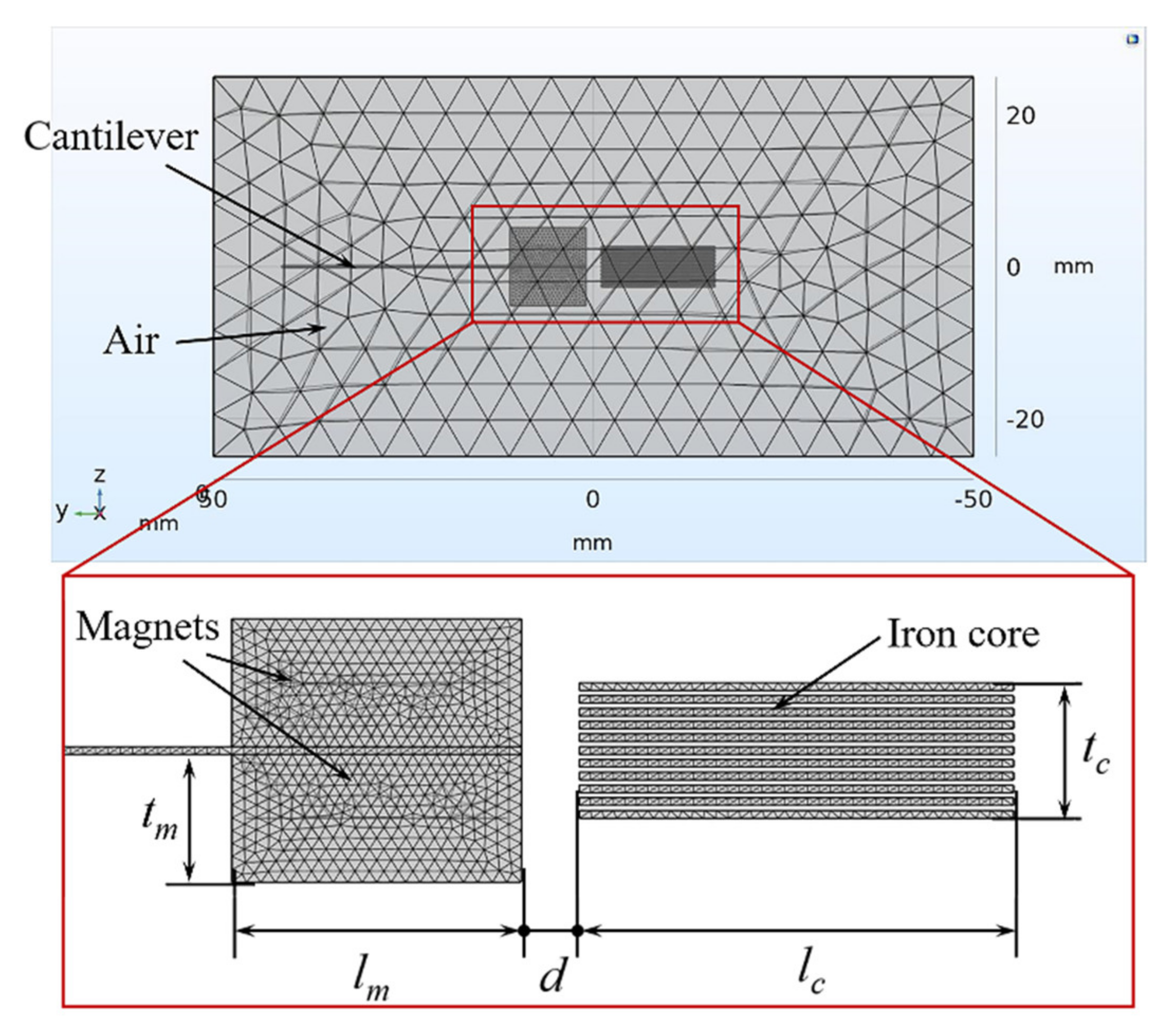
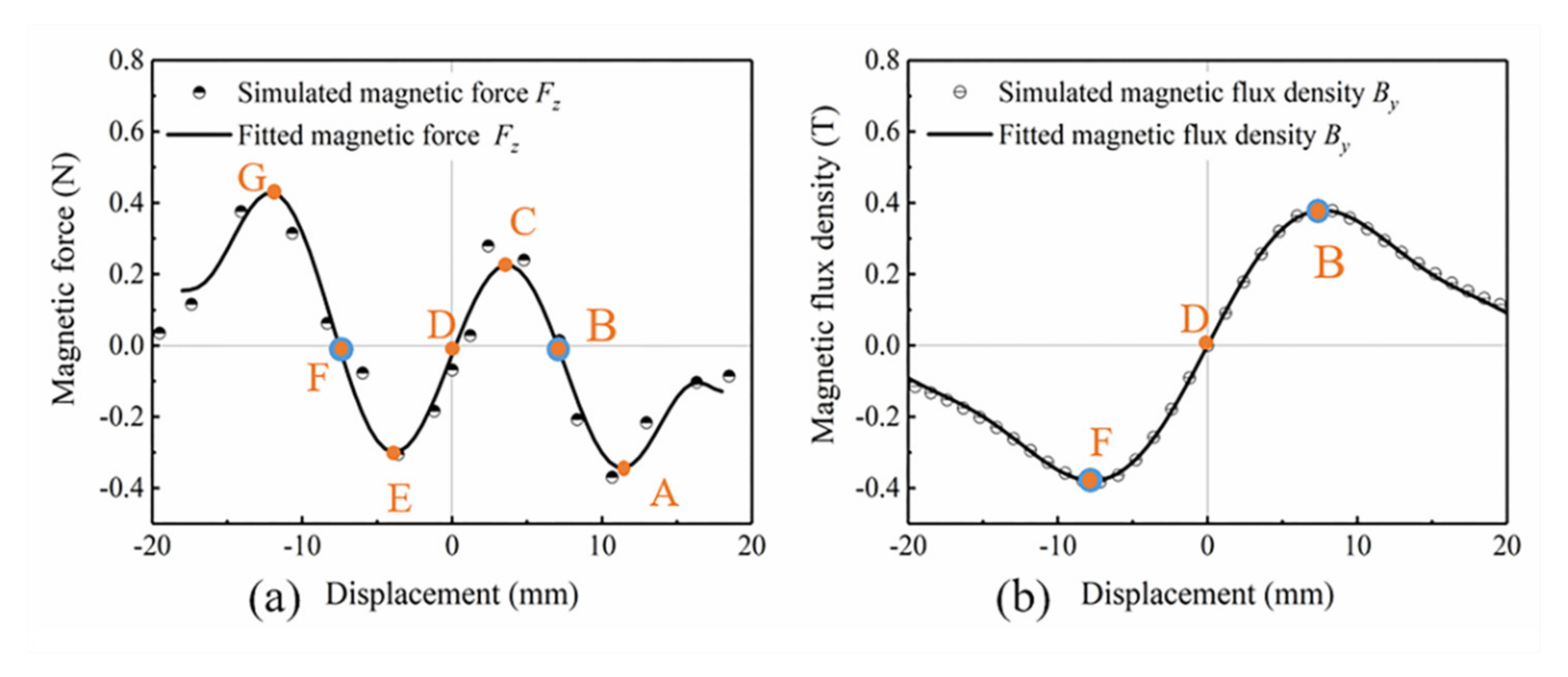
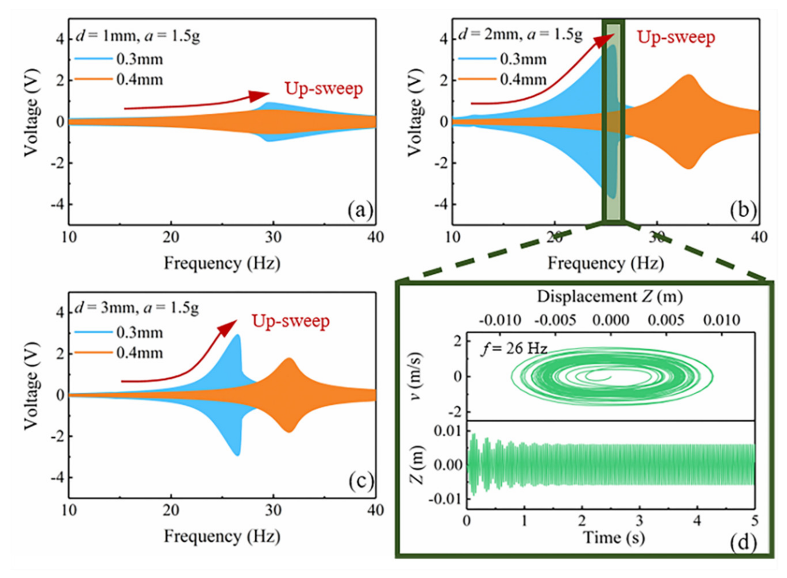
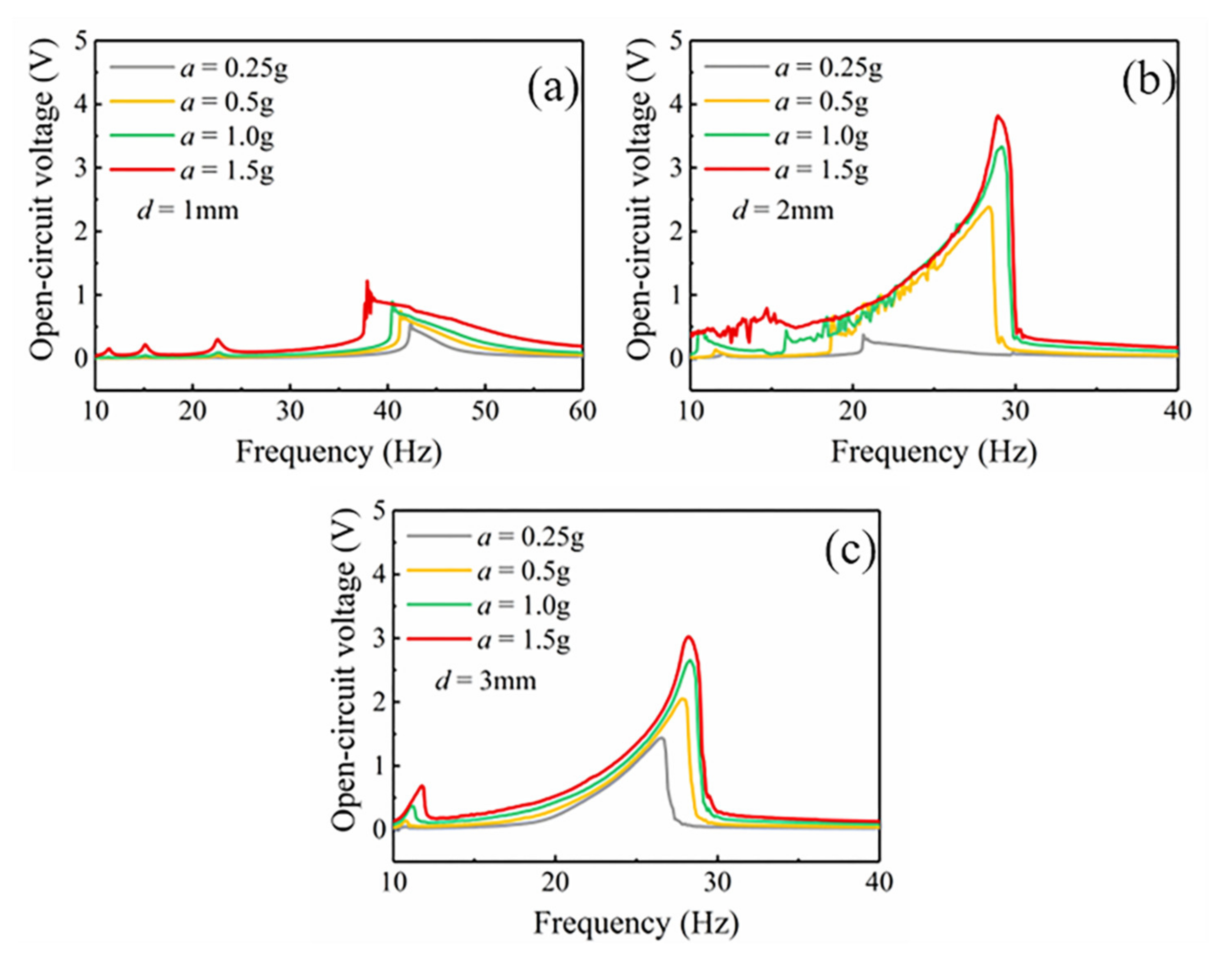
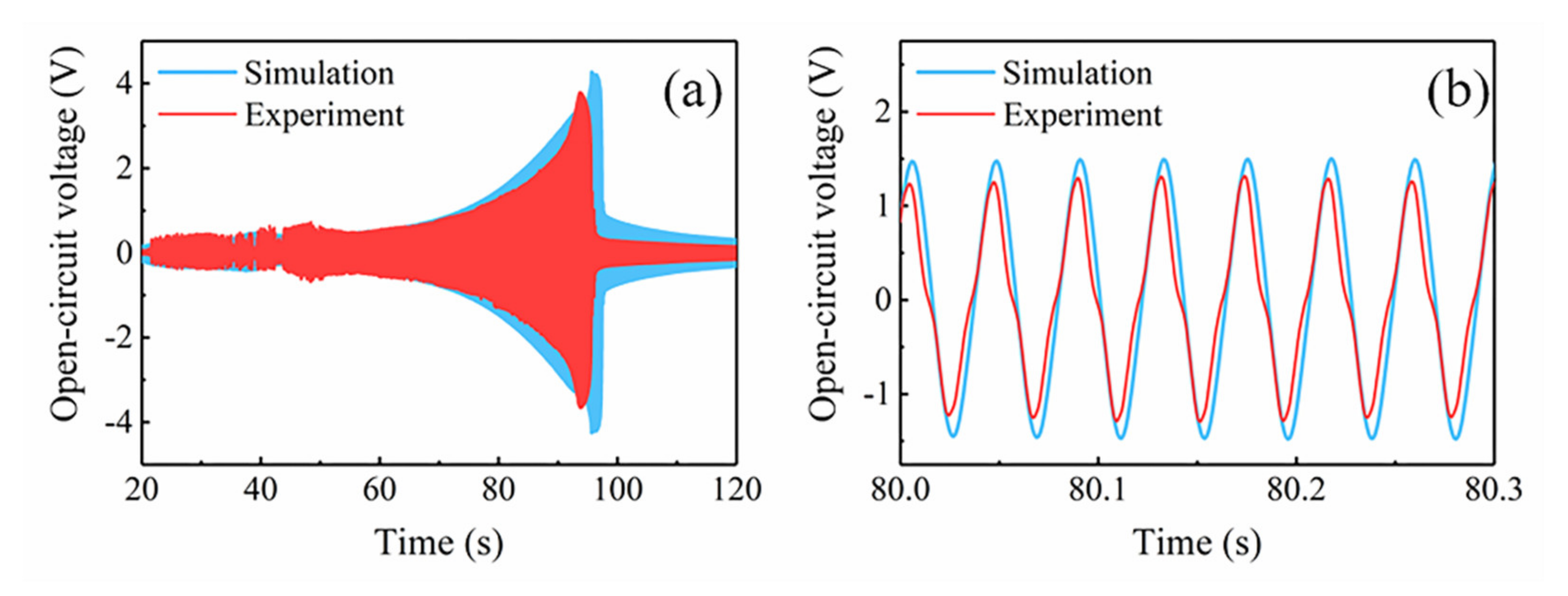
3. Simulation Analysis and Optimization

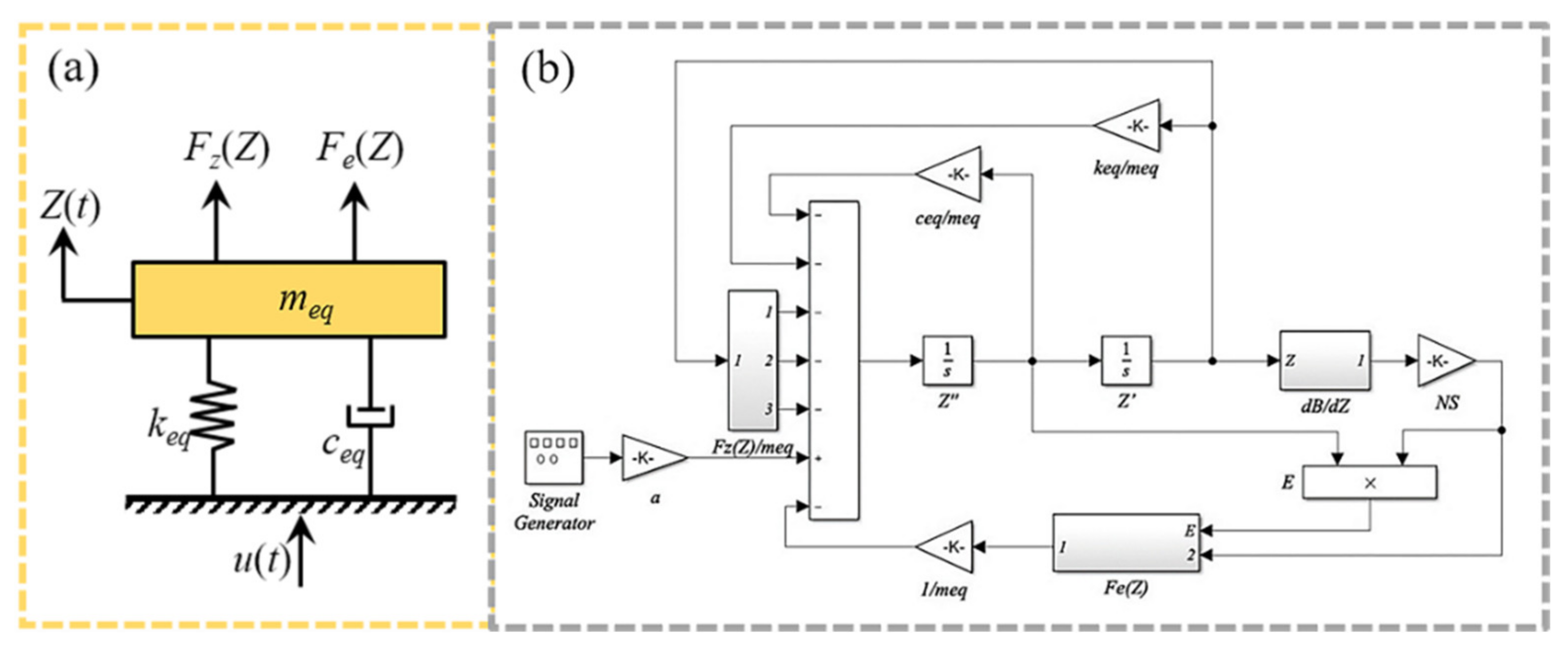
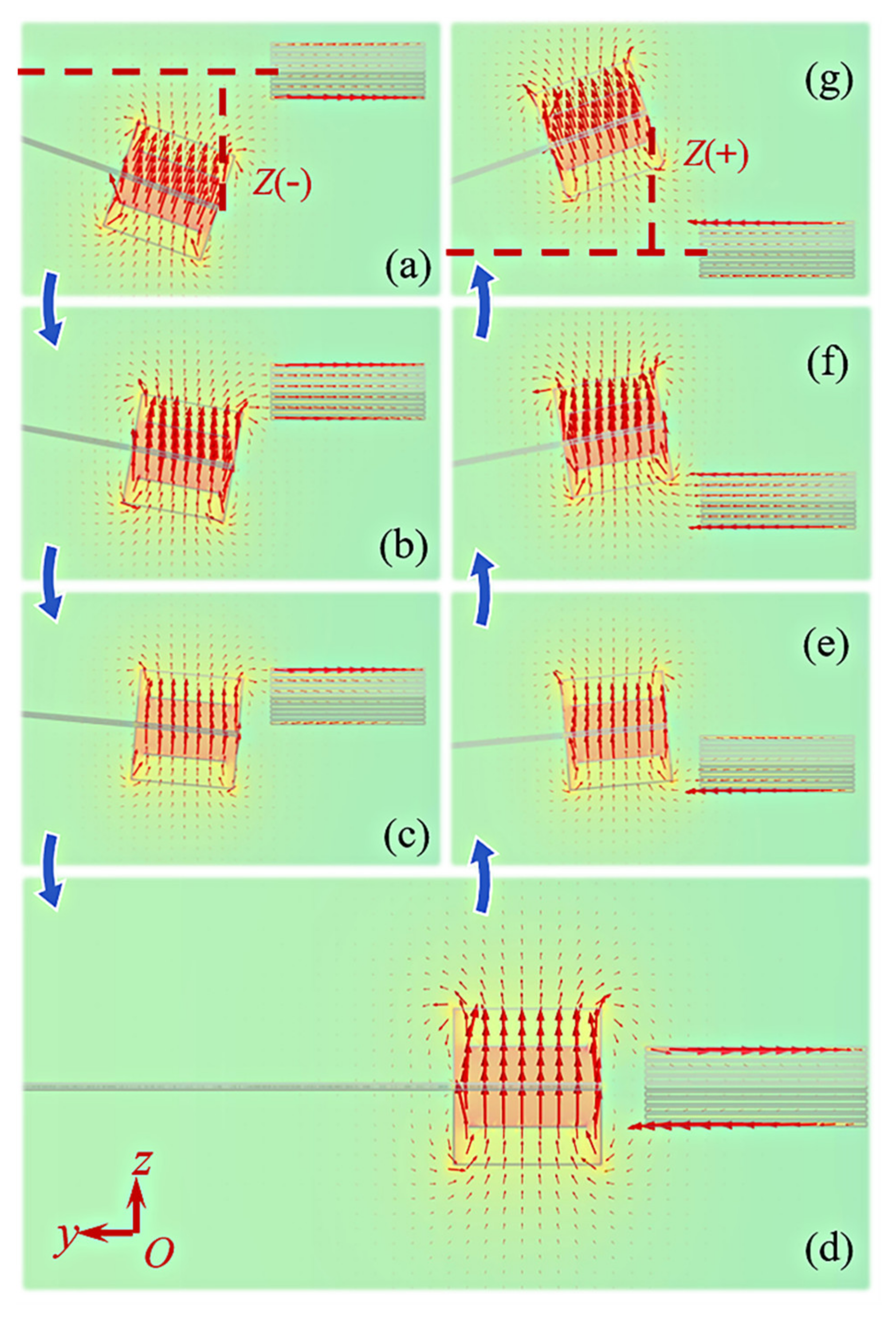
Analysis of Nonlinear Dynamics

Finite element analysis software COMSOL Multiphysics is used to simulate the magnetic field intensity and distribution at different displacements, and the simulation model is shown in Figure 3. The simulation results are shown in Figure 4. Placing an iron core near the magnets can guide the magnetic induction lines flowing from N pole of the magnets into the iron core, and then return to S pole after passing through the iron core. In addition to magnetic flux density inside the iron core, the magnetic force between the magnets and iron core can be also calculated by the magnetic field simulation. Using the curve fitting module in MATLAB, the polynomial function expression between the vertical magnetic force Fz and the displacement Z is fitted as Equation (3), the polynomial function expression between the horizontal magnetic flux density By and the displacement Z are fitted as
B y ( Z ) = q 0 + q 1 Z + + q m Z m ,
where q0, q1⋯⋯qm are the coefficients of the polynomial By(Z). The dBy/dZ can be used to calculate the induced voltage of the coil.
Figure 5 shows the comparison of the simulated scatter points and the fitted curves at different displacements Z from −20 to 20 mm when the initial gap distance d between the magnets and iron core is 2 mm. Within a certain error range, the variation trend and numerical value of the simulated scatter points and the fitted curves are basically coincided. Figure 5a shows the fitted curve of the nonlinear magnetic force Fz. When the value of Fz is positive, it means that the magnetic force of the iron core to magnets is along the positive direction of z-axis. Conversely, when the value of Fz is negative, the magnetic force of the iron core to magnet is along the negative direction of z-axis. As the displacement decreases from 20 mm to 0, the magnets are initially attracted by the iron core, and the attractive force gradually increases to the maximum value at displacement of 12 mm (point A). Then the attractive force drops to zero at displacement of 8 mm (point B). Next, the magnets are repelled by the iron core, and the repulsive force reaches the maximum value at 4 mm (point C), then decreases to zero at displacement of 0 (point D). Since the curve of Fz is symmetrical about the origin of the coordinate axis, the magnets are repelled first and then attracted when the displacement decreases from 0 to −20 mm. The maximum repulsive force, the maximum attractive force, and the magnetic force equal to zero appear at −4 (point E), −12 (point F), and −8 mm (point G), respectively. After the magnetic force reaches the peak point G, the distance between the magnet and the iron core increases as the displacement increases, and the magnetic field strength around the magnet decreases, so the magnetic force decreases.
Correspondingly, the distribution of the magnetic field intensity and magnetic induction lines at point A to G is shown in Figure 4a–g, respectively, and the fitted curve of the magnetic flux density By inside the iron core is depicted in Figure 5b. As shown in Figure 4a,g, the direction of magnetic induction lines inside the iron core at points A and G towards the positive and negative directions of y-axis, respectively. The iron core sheet closest to the magnet has the highest magnetic flux density, while the other sheets have very low magnetic flux density. The magnetic induction lines distribution at points B and F are shown in Figure 4b,f. It is seen that the magnetic induction lines introduced into the iron core are unidirectional and the number is the largest, so magnitude of By at these two points is the highest, as shown in Figure 5b. At points C (Figure 4c) and E (Figure 4e), since the iron core is close to the N and S poles of the magnets, the magnetic induction lines inside the iron core are bidirectional, resulting in a decrease of By. The magnetic induction lines start from the N pole into the iron core, then flow out from the iron core to the S pole. Figure 4d is the magnetic flux density distribution at point D. Here the N and S poles of the magnets are located on both sides of the iron core, the distance between the two magnetic poles and the center of the iron core is equal, so the magnetic induction lines flowing in and out of the iron core are equal. Thus, the magnetic flux density By decreases to zero at point D.
Based on the COMSOL magnetic field simulation and MATLAB curve fitting, the functional expression of the nonlinear magnetic force Fz(Z) and the gradient dBy/dZ of the magnetic flux density inside the iron core is obtained. According to the mathematical model, the voltage induced by the coil of the MNL-EMG under sinusoidal excitation is simulated. Since the gap distance between the magnets and iron core strongly affects the nonlinear magnetic force, the nonlinear response of the cantilever beam and the operating bandwidth of the MNL-EMG are simulated against different gap distances. Figure 6a–c depict the open-circuit voltage of the MNL-EMG with cantilever beam thickness of 0.3 and 0.4 mm against the frequency up-sweep as the gap distance d varying from 1, 2 to 3 mm, respectively, under acceleration of 1.5 g. It is seen that the MNL-EMG with beam thickness of 0.3 mm has higher voltage output and lower resonant frequency than that with beam thickness of 0.4 mm. The maximum output voltage occurs at gap distance of 2 mm and resonant frequency of 26 Hz. This is because the closer the magnets to the iron core, the greater the magnetic attraction along the y-axis direction. Once the gap distance is less than 1 mm, the magnet will be firmly attracted by the iron core, resulting in extremely low output voltage. As the gap distance increases, the attractive force along the y-axis direction decreases and the output voltage increases. However, the nonlinear magnetic force along the z-axis decreases with the increase of the distance. The nonlinearity of the voltage would be gradually weakened as the gap distance reaches 3 mm. The simulation results show that the MNL-EMG with a gap distance of 2 mm combines high output voltage and wide operating bandwidth. Figure 6d shows the phase trajectory and displacement of the MNL-EMG with gap distance of 2 mm when the excitation amplitude a is 1.5 g and the excitation frequency f is 26 Hz. The MB-EMG performs a large-amplitude periodic oscillation.

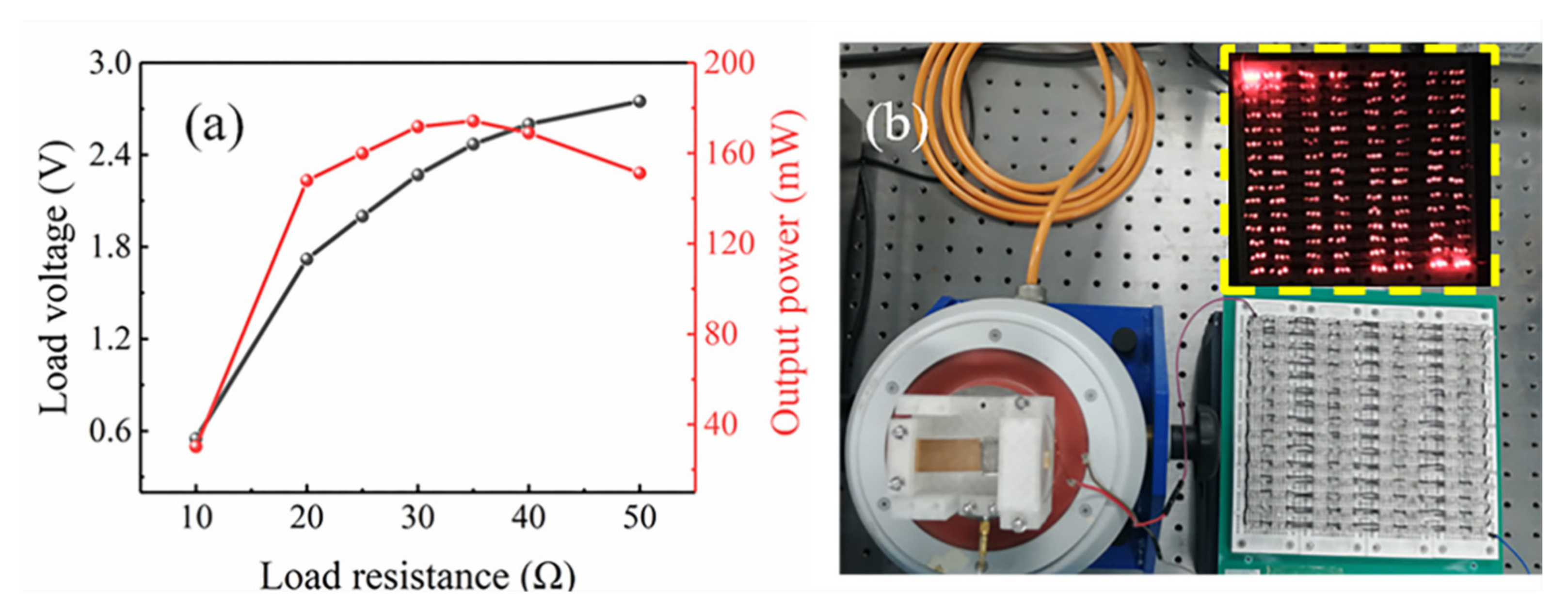
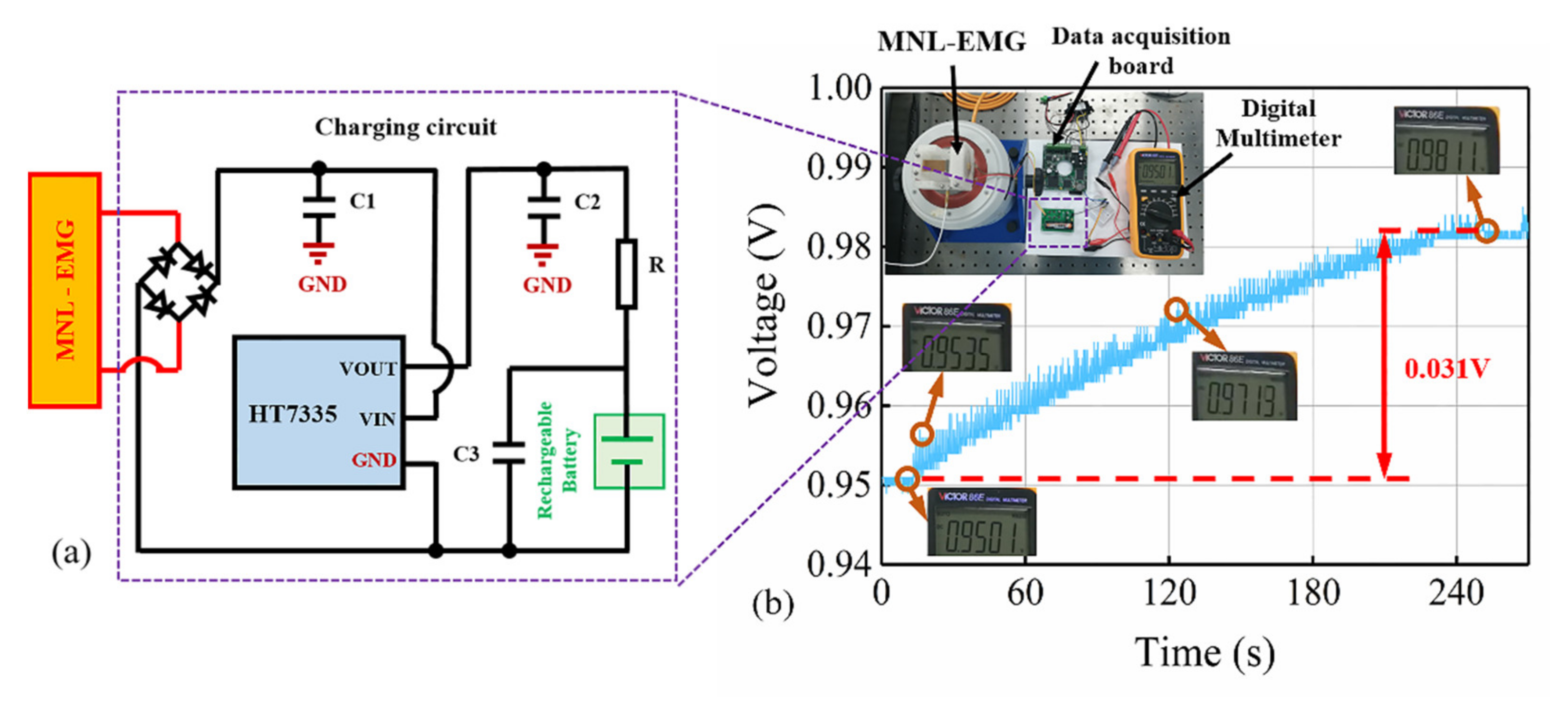
4. Experimental Results and Discussion

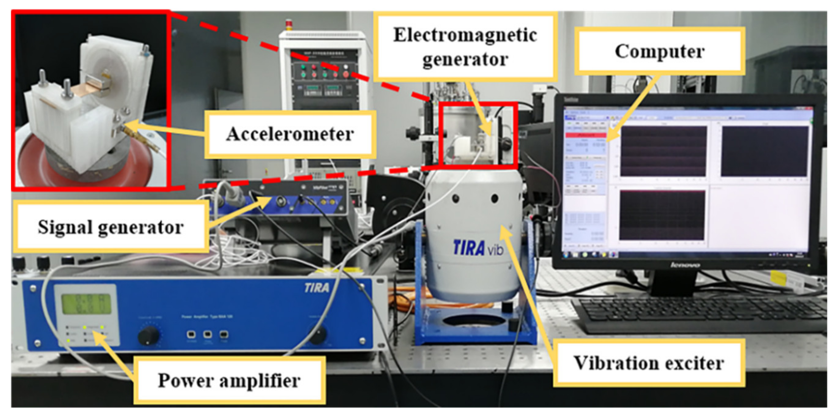
4.1. Experimental Setup

The output performance of the MNL-EMG was tested by the vibration control and testing system as shown in Figure 7. The system setup consists of a computer, a vibration exciter (TIRA TV 511110, Germany), a power amplifier (BAA 120), a signal generator (Vipilot 4 channels) and an accelerometer (DYTRAN model 3035BG, USA). The MNL-EMG prototype is fixed on the vibration exciter, and the sinusoidal excitation of the vibration exciter is generated by the signal generator through the power amplifier. The accelerometer is installed on the exciter to monitor the excitation acceleration and realize the closed-loop feedback control of the vibration control system. The frequency and acceleration of the sinusoidal excitation can be adjusted by the control software in the computer. The voltage output of the MNL-EMG in frequency and time domains can be accurately measured and recorded by the dynamic signal analysis software (m+p international VibRunner).

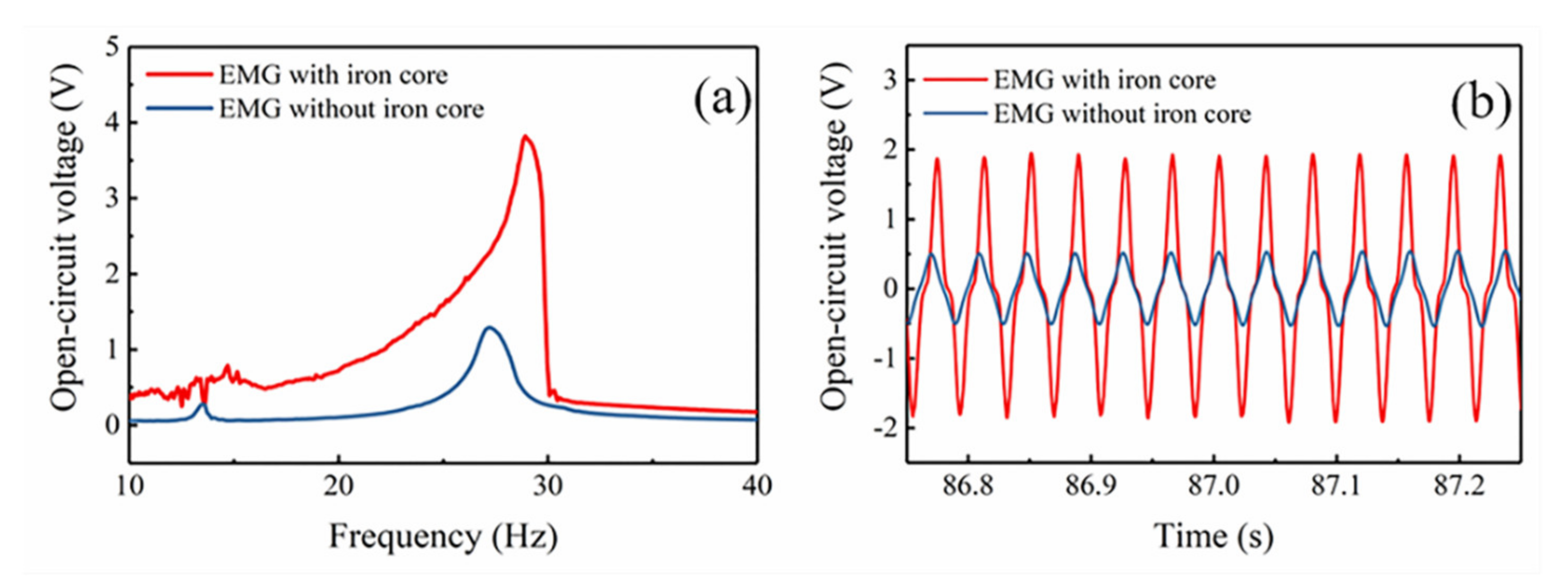
4.2. Results and Discussion

First, the EMG was subjected to a frequency upward sweep test using the vibration control and test system in the range of 10~40 Hz. As shown in Figure 8, the output performance of the EMG with and without iron core was compared under vibration acceleration of 1.5 g and gap distance of 2 mm. The resonant frequency of the EMG without iron core is 27 Hz, and the maximum output voltage at 27 Hz is 1.3 V. It is seen clearly that the voltage output of the MNL-EMG in frequency domain exhibits nonlinear characteristics, as shown in Figure 8a. The operating bandwidth of the MNL-EMG is 13 Hz (from 17 to 30 Hz), which is 4.3 times wider than that of the EMG without iron core, which is only 3 Hz (from 25.6 to 28.6 Hz). In addition, the high magnetic permeability of the iron core resulting in the increase of magnetic flux density inside the coil, so the output voltage of the MNL-EMG increases significantly. The maximum open-circuit voltage of the MNL-EMG (3.8 V at 29 Hz) is about 3 times higher than that of the EMG without iron core (1.3 V at 27 Hz). It is verified that the use of iron core with high magnetic permeability to the coil can broaden the operating bandwidth and improve the output performance effectively. The time domain diagrams of the open-circuit voltage of the EMG with iron core and without iron core are depicted in Figure 8b.
The output performance of the MNL-EMG is strongly affected by the gap distance d between the magnet and iron core, as well as the acceleration of the excitation. Figure 9 shows the measured open-circuit voltage of the MNL-EMG against operating frequency at various acceleration levels of 0.25, 0.5, 1, and 1.5 g, under the gap distance of 1, 2, and 3 mm, respectively. It is seen the open-circuit voltage outputs of the MNL-EMG are quite low at the gap distance of 1 mm. This is because the magnetic attraction along y-axis is very strong, the deflection of the cantilever beam is strongly restricted by the magnetic attraction force. In contrast, under gap distance of 2 mm, the open-circuit voltage of the MNL-EMG is 2.39, 3.33 and 3.82 V at acceleration of 0.5, 1.0 and 1.5 g, respectively, which are higher than those of the MNL-EMG under gap distance of 3 mm. The maximum output voltage is 3.82 V at excitation frequency of 30 Hz. It should be noted that the open-circuit voltage of the MNL-EMG at acceleration of 0.25 g and under gap distance of 2 mm is 0.37 V, which is much lower than that of the MNL-EMG under gap distance of 3 mm. It can be inferred that greater acceleration is required to enhance the nonlinear response of the cantilever, therefore increasing the output voltage and broadening the bandwidth. Figure 10 shows the comparison of the simulated and tested waveform diagrams of the open-circuit voltage against frequency up-sweep at vibration acceleration of 1.5 g and under gap distance of 2 mm. The waveforms of the open-circuit voltage obtained by simulation and experiment are consistent, indicating that the established system dynamic model is suitable for this MNL-EMG device.
Figure 11a shows the peak load voltage and maximum output power of the MNL-EMG versus load resistance at acceleration of 1.5 g and frequency of 30 Hz. The MNL-EMG can be regarded as a voltage source with an open-circuit voltage of E and an internal resistance of r equal to the resistance of the coil. With the increasing of load resistance, the load voltage continues to increase, while the corresponding power reaches to a maximum value of 174 mW at the optimal load resistance of 35 Ω. The maximum output power of MNL-EMG is 10.8 times higher than that of the EMG without iron core. Figure 11b demonstrated that the MNL-EMG can light up more than 360 parallel-connected LEDs. Moreover, to examine the charging performance of the MNL-EMG, the output of the MNL-EMG is connected to a rectifier to convert the AC input signal into a DC signal. Then the HT7335 voltage regulator chip converts the rectified DC voltage into a stable DC voltage to charge the battery, as shown in Figure 12a. The rechargeable battery is a Ni-MH battery with 1.2 V nominal voltage and 900 mAh nominal capacity. Figure 12b presents the voltage of the battery during the experiment. The battery voltage was 0.95 V at the beginning. After the charging process of 240 s, the stable voltage of the rechargeable battery increased to 0.98 V. In real applications, the MNL-EMG is designed to harvest the vibration energy generated by these mechanical devices, such as vibrating screen, coal mining machine, pump, gear box, etc., to power the sensors and eventually build a self-powered wireless sensing network.
Performance comparison between the introduced MNL-EMG and recent published low-frequency vibration generators in the literature is given in Table 2. It is worth pointing out that a fair comparison may need to re-design the energy harvester for the specific working condition, which is quite difficult. The acceleration, operating frequency range, and power density somehow generalized working condition and performance parameter. As the data shown in Table 2, previous works investigated different transaction mechanisms for the low-frequency vibration. The MNL-EMG in this work can generate a high power output and a wide bandwidth at relatively large acceleration, which indicates its superior performance over other vibration generators in the large-amplitude vibration environment. In general, the introduced MNL-EMG device has achieved high output power, wide working bandwidth, and low working frequency, simultaneously. It can easily capture the low-frequency environmental vibration energy, and the output power is sufficient to power micro electronic devices. In the subsequent research, we will continue the integration of the power management circuit for the MNL-EMG and build a complete power supply system, which would have broad application prospects.

5. Conclusions

This paper presents a MNL-EMG with wide bandwidth and high performance. In this MNL-EMG, advantages of several technologies are combined to enhance the output performance: (1) the nonlinear attraction between magnets and iron core enable the cantilever beam to operate in a high-energy orbit to generate wider operating bandwidth and higher output power; (2) iron core with high-permeability guides the magnetic induction lines into the coil, therefore greatly increased the electromagnetic output power while performing nonlinear motion. To reveal the mechanism of nonlinear effect, the magnetic force of the iron core to the magnets and the magnetic flux density inside the iron core at different displacements are simulated and analyzed. Based on the dynamic model, the output voltage of the MNL-EMG is simulated, and the dimension parameters are optimized. Then a series of experiments are conducted to test the output performance of the prototype. Under an acceleration of 1.5 g, the MNL-EMG can maintain high output power in the ultra-wide frequency range of 17~30 Hz, and the operating bandwidth reaches 13 Hz, which is 4.3 times wider than that of linear EMG without an iron core. The maximum output power of the MNL-EMG reaches 174 mW under the optimal load resistance of 35 Ω, and the prototype can light up 360 LEDs. Moreover, the prototype can charge a Ni-MH rechargeable battery (1.2 V, 900 mAh) from 0.95 V to 0.98 V within 240 s. It is proved that the proposed MNL-EMG has advantages of wide operating bandwidth and extremely high output power. This research can be of great significance for further exploration of nonlinear vibration energy harvester.

Author Contributions

Conceptualization, M.H. and H.L.; methodology, M.H. and X.F.; software, M.H. and Y.L.; validation, M.H. and T.T.; formal analysis, M.H. and T.C.; writing—original draft preparation, M.H. and X.F.; writing—review and editing, M.H. and H.L.; project administration, H.L. and T.C.; funding acquisition, H.L. and L.S. All authors have read and agreed to the published version of the manuscript.

Funding

This research was funded by the National Key Research and Development Program of China (Grant No. 2019YFB2004800) and the National Natural Science Foundation of China (Grant No. 51875377).

Conflicts of Interest

The authors declare no conflict of interest.

References

  1. Liu, H.; Zhong, J.; Lee, C.; Lee, S.-W.; Lin, L. A comprehensive review on piezoelectric energy harvesting technology: Materials, mechanisms, and applications. Appl. Phys. Rev. 2018, 5, 041306. [Google Scholar] [CrossRef]
  2. Zou, H.X.; Zhao, L.C.; Gao, Q.H.; Zuo, L.; Liu, F.R.; Tan, T.; Wei, K.X.; Zhang, W.M. Mechanical modulations for enhancing energy harvesting: Principles, methods and applications. Appl. Energy 2019, 255, 113871. [Google Scholar] [CrossRef]
  3. Hou, C.; Chen, T.; Li, Y.; Huang, M.; Shi, Q.; Liu, H.; Sun, L.; Lee, C. A rotational pendulum based electromagnetic/triboelectric hybrid-generator for ultra-low-frequency vibrations aiming at human motion and blue energy applications. Nano Energy 2019, 63, 103871. [Google Scholar] [CrossRef]
  4. Yang, Z.; Zhu, Y.; Zu, J. Theoretical and experimental investigation of a nonlinear compressive-mode energy harvester with high power output under weak excitations. Smart Mater. Struct. 2015, 24, 025028. [Google Scholar] [CrossRef]
  5. Liu, H.; Hou, C.; Lin, J.; Li, Y.; Shi, Q.; Chen, T.; Sun, L.; Lee, C. A non-resonant rotational electromagnetic energy harvester for low-frequency and irregular human motion. Appl. Phys. Lett. 2018, 113, 203901. [Google Scholar] [CrossRef] [Green Version]
  6. Shen, Y.; Lu, K. Scavenging power from ultra-low frequency and large amplitude vibration source through a new non-resonant electromagnetic energy harvester. Energy Convers. Manag. 2020, 222, 113233. [Google Scholar] [CrossRef]
  7. Yan, B.; Yu, N.; Zhang, L.; Ma, H.; Wu, C.; Wang, K.; Zhou, S. Scavenging vibrational energy with a novel bistable electromagnetic energy harvester. Smart Mater. Struct. 2020, 29, 025022. [Google Scholar] [CrossRef]
  8. Li, Y.; Guo, Q.; Huang, M.; Ma, X.; Chen, Z.; Liu, H.; Sun, L. Study of an Electromagnetic Ocean Wave Energy Harvester Driven by an Efficient Swing Body Toward the Self-Powered Ocean Buoy Application. IEEE Access 2019, 7, 129758–129769. [Google Scholar] [CrossRef]
  9. Huang, M.; Hou, C.; Li, Y.; Liu, H.; Wang, F.; Chen, T.; Yang, Z.; Tang, G.; Sun, L. A Low-Frequency MEMS Piezoelectric Energy Harvesting System Based on Frequency Up-Conversion Mechanism. Micromachines 2019, 10, 639. [Google Scholar] [CrossRef] [PubMed] [Green Version]
  10. Tang, L.; Yang, Y. A nonlinear piezoelectric energy harvester with magnetic oscillator. Appl. Phys. Lett. 2012, 101, 094102. [Google Scholar] [CrossRef]
  11. Yang, B.; Yi, Z.; Tang, G.; Liu, J. A gullwing-structured piezoelectric rotational energy harvester for low frequency energy scavenging. Appl. Phys. Lett. 2019, 115, 063901. [Google Scholar] [CrossRef]
  12. Cao, J.; Lin, J.; Inman, D.J.; Zhou, S. Nonlinear Dynamic Characteristics of Variable Inclination Magnetically Coupled Piezoelectric Energy Harvesters. J. Vib. Acoust. 2015, 137, 021015. [Google Scholar] [CrossRef]
  13. Machado, L.Q.; Yurchenko, D.; Wang, J.; Clementi, G.; Margueron, S.; Bartasyte, A. Multi-dimensional constrained energy optimization of a piezoelectric harvester for E-gadgets. iScience 2021, 24, 102749. [Google Scholar] [CrossRef]
  14. Tao, K.; Lye, S.W.; Miao, J.; Tang, L.; Hu, X. Out-of-plane electret-based MEMS energy harvester with the combined nonlinear effect from electrostatic force and a mechanical elastic stopper. J. Micromech. Microeng. 2015, 25, 104014. [Google Scholar] [CrossRef]
  15. Vysotskyi, B.; Aubry, D.; Gaucher, P.; Le Roux, X.; Parrain, F.; Lefeuvre, E. Nonlinear electrostatic energy harvester using compensational springs in gravity field. J. Micromech. Microeng. 2018, 28, 074004. [Google Scholar] [CrossRef]
  16. Zhang, Y.; Wang, T.; Luo, A.; Hu, Y.; Li, X.; Wang, F. Micro electrostatic energy harvester with both broad bandwidth and high normalized power density. Appl. Energy 2018, 212, 362–371. [Google Scholar] [CrossRef]
  17. Shi, Q.; Wang, H.; Wu, H.; Lee, C. Self-powered triboelectric nanogenerator buoy ball for applications ranging from environment monitoring to water wave energy farm. Nano Energy 2017, 40, 203–213. [Google Scholar] [CrossRef]
  18. Zhu, G.; Lin, Z.H.; Jing, Q.; Bai, P.; Pan, C.; Yang, Y.; Zhou, Y.; Wang, Z.L. Toward large-scale energy harvesting by a nanoparticle-enhanced triboelectric nanogenerator. Nano Lett. 2013, 13, 847–853. [Google Scholar] [CrossRef]
  19. Zhao, X.; Wei, G.; Li, X.; Qin, Y.; Xu, D.; Tang, W.; Yin, H.; Wei, X.; Jia, L. Self-powered triboelectric nano vibration accelerometer based wireless sensor system for railway state health monitoring. Nano Energy 2017, 34, 549–555. [Google Scholar] [CrossRef] [Green Version]
  20. Yu, J.; Hou, X.; He, J.; Cui, M.; Wang, C.; Geng, W.; Mu, J.; Han, B.; Chou, X. Ultra-flexible and high-sensitive triboelectric nanogenerator as electronic skin for self-powered human physiological signal monitoring. Nano Energy 2020, 69, 104437. [Google Scholar] [CrossRef]
  21. Kim, S.; Towfeeq, I.; Dong, Y.; Gorman, S.; Rao, A.; Koley, G. P(VDF-TrFE) Film on PDMS Substrate for Energy Harvesting Applications. Appl. Sci. 2018, 8, 213. [Google Scholar] [CrossRef] [Green Version]
  22. Lapčinskis, L.; Malnieks, K.; Linarts, A.; Blums, J.; Šmits, K.; Järvekülg, M.; Knite, M.; Šutka, A. Hybrid Tribo-Piezo-Electric Nanogenerator with Unprecedented Performance Based on Ferroelectric Composite Contacting Layers. ACS Appl. Energ. Mater. 2019, 2, 4027–4032. [Google Scholar] [CrossRef]
  23. Han, M.; Zhang, X.-S.; Meng, B.; Liu, W.; Tang, W.; Sun, X.; Wang, W.; Zhang, H. r-Shaped Hybrid Nanogenerator with Enhanced Piezoelectricity. ACS Nano 2013, 7, 8554–8560. [Google Scholar] [CrossRef] [PubMed]
  24. Ma, T.; Gao, Q.; Li, Y.; Wang, Z.; Lu, X.; Cheng, T. An Integrated Triboelectric–Electromagnetic–Piezoelectric Hybrid Energy Harvester Induced by a Multifunction Magnet for Rotational Motion. Adv. Eng. Mater. 2019, 22, 1900872. [Google Scholar] [CrossRef]
  25. Gao, Y.J.; Leng, Y.G.; Fan, S.B.; Lai, Z.H. Performance of bistable piezoelectric cantilever vibration energy harvesters with an elastic support external magnet. Smart Mater. Struct. 2014, 23, 095003. [Google Scholar] [CrossRef]
  26. Liu, H.; Lee, C.; Kobayashi, T.; Tay, C.J.; Quan, C. Investigation of a MEMS piezoelectric energy harvester system with a frequency-widened-bandwidth mechanism introduced by mechanical stoppers. Smart Mater. Struct. 2012, 21, 035005. [Google Scholar] [CrossRef]
  27. Toyabur, R.M.; Salauddin, M.; Cho, H.; Park, J.Y. A multimodal hybrid energy harvester based on piezoelectric-electromagnetic mechanisms for low-frequency ambient vibrations. Energy Convers. Manag. 2018, 168, 454–466. [Google Scholar] [CrossRef]
  28. Dhote, S.; Li, H.; Yang, Z. Multi-frequency responses of compliant orthoplanar spring designs for widening the bandwidth of piezoelectric energy harvesters. Int. J. Mech. Sci. 2019, 157–158, 684–691. [Google Scholar] [CrossRef]
  29. Liu, H.; Koh, K.H.; Lee, C. Ultra-wide frequency broadening mechanism for micro-scale electromagnetic energy harvester. Appl. Phys. Lett. 2014, 104, 053901. [Google Scholar] [CrossRef]
  30. Leland, E.S.; Wright, P.K. Resonance tuning of piezoelectric vibration energy scavenging generators using compressive axial preload. Smart Mater. Struct. 2006, 15, 1413–1420. [Google Scholar] [CrossRef]
  31. Hajati, A.; Kim, S.-G. Ultra-wide bandwidth piezoelectric energy harvesting. Appl. Phys. Lett. 2011, 99, 083105. [Google Scholar] [CrossRef] [Green Version]
  32. Stanton, S.C.; McGehee, C.C.; Mann, B.P. Reversible hysteresis for broadband magnetopiezoelastic energy harvesting. Appl. Phys. Lett. 2009, 95, 174103. [Google Scholar] [CrossRef]
  33. Li, H.T.; Qin, W.Y. Prompt efficiency of energy harvesting by magnetic coupling of an improved bi-stable system. Chin. Phys. B 2016, 25, 110503. [Google Scholar] [CrossRef]
  34. Cao, J.; Wang, W.; Zhou, S.; Inman, D.J.; Lin, J. Nonlinear time-varying potential bistable energy harvesting from human motion. Appl. Phys. Lett. 2015, 107, 143904. [Google Scholar] [CrossRef]
  35. Gao, Y.; Leng, Y.; Javey, A.; Tan, D.; Liu, J.; Fan, S.; Lai, Z. Theoretical and applied research on bistable dual-piezoelectric-cantilever vibration energy harvesting toward realistic ambience. Smart Mater. Struct. 2016, 25, 115032. [Google Scholar] [CrossRef]
  36. Liu, H.; Lee, C.; Kobayashi, T.; Tay, C.J.; Quan, C. Piezoelectric MEMS-based wideband energy harvesting systems using a frequency-up-conversion cantilever stopper. Sens. Actuators A Phys. 2012, 186, 242–248. [Google Scholar] [CrossRef]
  37. Fu, H.; Zhou, S.; Yeatman, E.M. Exploring coupled electromechanical nonlinearities for broadband energy harvesting from low-frequency rotational sources. Smart Mater. Struct. 2019, 28, 075001. [Google Scholar] [CrossRef]
  38. Stanton, S.C.; Mann, B.P.; Owens, B.A.M. Melnikov theoretic methods for characterizing the dynamics of the bistable piezoelectric inertial generator in complex spectral environments. Phys. D 2012, 241, 711–720. [Google Scholar] [CrossRef]
  39. Bouhedma, S.; Zheng, Y.; Lange, F.; Hohlfeld, D. Magnetic Frequency Tuning of a Multimodal Vibration Energy Harvester. Sensors 2019, 19, 1149. [Google Scholar] [CrossRef] [Green Version]
  40. Aldawood, G.; Nguyen, H.T.; Bardaweel, H. High power density spring-assisted nonlinear electromagnetic vibration energy harvester for low base-accelerations. Appl. Energy 2019, 253, 113546. [Google Scholar] [CrossRef]
  41. Mann, B.P.; Sims, N.D. Energy harvesting from the nonlinear oscillations of magnetic levitation. J. Sound Vib. 2009, 319, 515–530. [Google Scholar] [CrossRef] [Green Version]
  42. Chen, Y.; Pollock, T.E.; Salehian, A. Analysis of compliance effects on power generation of a nonlinear electromagnetic energy harvesting unit; theory and experiment. Smart Mater. Struct. 2013, 22, 094027. [Google Scholar] [CrossRef]
  43. Lu, Z.; Wen, Q.; He, X.; Wen, Z. A Nonlinear Broadband Electromagnetic Vibration Energy Harvester Based on Double-Clamped Beam. Energies 2019, 12, 2710. [Google Scholar] [CrossRef] [Green Version]
  44. Sun, S.; Dai, X.; Wang, K.; Xiang, X.; Ding, G.; Zhao, X. Nonlinear Electromagnetic Vibration Energy Harvester With Closed Magnetic Circuit. IEEE Magn. Lett. 2018, 9, 1–4. [Google Scholar] [CrossRef]
  45. Xing, X.; Lou, J.; Yang, G.M.; Obi, O.; Driscoll, C.; Sun, N.X. Wideband vibration energy harvester with high permeability magnetic material. Appl. Phys. Lett. 2009, 95, 134103. [Google Scholar] [CrossRef]
  46. Xing, X.; Yang, G.M.; Liu, M.; Lou, J.; Obi, O.; Sun, N.X. High power density vibration energy harvester with high permeability magnetic material. J. Appl. Phys. 2011, 109, 07E514. [Google Scholar] [CrossRef]
  47. Ren, Z.; Zhao, H.; Liu, C.; Qian, L.; Zhang, S.; Zhao, J. Study the influence of magnetic force on nonlinear energy harvesting performance. AIP Adv. 2019, 9, 105107. [Google Scholar] [CrossRef]
  48. Haroun, A.; Yamada, I.; Warisawa, S.i. Micro electromagnetic vibration energy harvester based on free/impact motion for low frequency–large amplitude operation. Sens. Actuators A Phys. 2015, 224, 87–98. [Google Scholar] [CrossRef]
  49. Gu, Y.; Liu, W.; Zhao, C.; Wang, P. A goblet-like non-linear electromagnetic generator for planar multi-directional vibration energy harvesting. Appl. Energy 2020, 266, 114846. [Google Scholar] [CrossRef]
  50. Fan, K.; Liu, S.; Liu, H.; Zhu, Y.; Wang, W.; Zhang, D. Scavenging energy from ultra-low frequency mechanical excitations through a bi-directional hybrid energy harvester. Appl. Energy 2018, 216, 8–20. [Google Scholar] [CrossRef]
  51. Salauddin, M.; Rasel, M.S.; Kim, J.W.; Park, J.Y. Design and experiment of hybridized electromagnetic-triboelectric energy harvester using Halbach magnet array from handshaking vibration. Energy Convers. Manag. 2017, 153, 1–11. [Google Scholar] [CrossRef]
  52. Askari, H.; Asadi, E.; Saadatnia, Z.; Khajepour, A.; Khamesee, M.B.; Zu, J. A hybridized electromagnetic-triboelectric self-powered sensor for traffic monitoring: Concept, modelling, and optimization. Nano Energy 2017, 32, 105–116. [Google Scholar] [CrossRef]
Figure 1. (a) Structure of the magnetic-coupled nonlinear electromagnetic generator (MNL-EMG). Distribution of magnetic induction lines around the magnets and iron core as the magnets are (b) above or (c) below the iron core. (d) Schematic diagram of the MNL-EMG.
Micromachines 12 00912 g001
Figure 2. (a) Equivalent model and (b) MATLAB/Simulink diagram of the MNL-EMG.
Micromachines 12 00912 g002
Figure 3. COMSOL magnetic field simulation model diagram.
Micromachines 12 00912 g003
Figure 4. The magnetic field intensity and distribution at different displacements: (a) Z = 12 mm (point A); (b) Z = 8 mm (point B); (c) Z = 4 mm (point C); (d) Z = 0 (point D); (e) Z = −4 mm (point E); (f) Z = −8 mm (point F); (g) Z = −12 mm (point G).
Micromachines 12 00912 g004
Figure 5. Fitted curves of (a) magnetic force Fz and (b) magnetic flux density By at distance of 2 mm.
Micromachines 12 00912 g005
Figure 6. The simulated open-circuit voltage of the MNL-EMG with beam thickness of 0.3 mm and 0.4 mm, under gap distance of (a) 1 mm, (b) 2 mm, and (c) 3 mm. (d) The phase trajectory and displacement of the MNL-EMG with gap distance of 2 mm when the excitation acceleration a is 1.5 g and the excitation frequency f is 26 Hz.
Micromachines 12 00912 g006
Figure 7. The experimental setup and the prototype.
Micromachines 12 00912 g007
Figure 8. (a) Frequency domain and (b) time domain diagrams of the open-circuit voltage of the EMG with iron core and without iron core.
Micromachines 12 00912 g008
Figure 9. The open-circuit voltage outputs of the MNL-EMG at different accelerations under the distance d of (a) 1 mm, (b) 2 mm and (c) 3 mm, respectively.
Micromachines 12 00912 g009
Figure 10. (a,b) The tested and simulated time domain waveform diagrams of the open-circuit voltage of the MNL-EMG at acceleration of 1.5 g, under distance of 2 mm.
Micromachines 12 00912 g010
Figure 11. (a) The load voltage and maximum output power of the MNL-EMG versus load resistance. (b) Photograph of LEDs that are lighted up by MNL-EMG.
Micromachines 12 00912 g011
Figure 12. (a) Experimental circuit and (b) battery charging experiment.
Micromachines 12 00912 g012
Table 1. Geometric dimensions of the MNL-EMG.
ParameterValue
Length of the cantilever beam lc40 mm
Width of the cantilever beam Wc13 mm
Thickness of the cantilever beam tc0.3 mm
Length of the magnet lm10 mm
Width of the magnet Wm15 mm
Thickness of the magnet tm5 mm
Length of the iron core ls15 mm
Width of the iron core Ws7 mm
Thickness of the iron core ts7 mm
Distance between the magnet and iron core d2 mm
Diameter of the copper wire r0.3 mm
Diameter of the coil R30 mm
Turns of the coil N500
Table 2. Performance comparison between the MNL-EMG and low-frequency vibration generators reported in the literature.
ReferenceTransducerAcceleration (g)Frequency (Hz)Bandwidth (Hz)Power (mW)
Ren [47]PE0.212~14.52.51.40
Shen [6]EM3.253~6323.2
Yan [7]EM0.65~151028
Aldawood [40]EM0.47~12580
Sun [44]EM0.557.4~64.77.30.003
Haroun [48]EM1.263.33--0.083
Gu [49]EM1.05~27227.65
Toyabur [27]EM and PE0.412~22100.49
Fan [50]EM and PE1.56~8.52.51.42
Salauddin [51]EM and TE0.55--11.75
Askari [52]EM and TE0.5745.45~55.451074
This workEM1.517~3013174
g = 9.8 m/s2, PE = piezoelectric, EM = electromagnetic, TE = triboelectric.
Publisher’s Note: MDPI stays neutral with regard to jurisdictional claims in published maps and institutional affiliations.

