Article

Scratch Behaviour of Bulk Silicon Nitride Ceramics

School of Mechanical and Electrical Engineering, Guangdong University of Technology, Guangzhou 510006, China
*
Author to whom correspondence should be addressed.
Micromachines 2021, 12(6), 707; https://doi.org/10.3390/mi12060707
Submission received: 21 May 2021 / Revised: 13 June 2021 / Accepted: 14 June 2021 / Published: 16 June 2021

Abstract

:
Si3N4 ceramic is generally recognized as being difficult to machine due to its hardness and brittleness. It is necessary to control the normal load applied and the machined depth of the abrasive particles in order to eliminate surface/subsurface damage and defects during the grinding or polishing. In this study, scratch experiments were conducted on the polished surface of Si3N4 specimens to investigate the brittle–ductile transformation and the evolution of material removal mechanisms. In addition, the cracking behaviour of Si3N4 ceramic was characterized by indentation tests. The Vickers indentation produced cracks that exhibited good developmental integrity and geometric symmetry. The results indicate that the scratch track can be divided into three stages: the ductile regime, the brittle–ductile coexisting stage, and the brittle fracture regime. The critical loads and the corresponding penetration depths of cracking occurrence in Si3N4 were recorded. The material removal of Si3N4 ceramic was primary attributed to ductile regime removal when the load was less than 9.8 N. Microcrack initiation on the subsurface was observed when the penetration depth of the scratch tip reached 8 μm or the depth of the indentation tip reached 3.2 μm. Microcracks expanded rapidly as the load was further increased, resulting in a brittle fracture of the Si3N4 ceramic.

1. Introduction

Silicon nitride (Si3N4) ceramics are widely used in various industrial sectors owing to their excellent physical–mechanical properties, such as their high strength, low density, high thermal shock resistance, low friction coefficient, high abrasion, and corrosion resistance. However, the hardness and brittleness make parts made of Si3N4 ceramics difficult to machine [1,2]. In general, surface defects, including scratches, dimples, pit defects, and microcracks, can be found on the surface after abrasive polishing due to the fracture of the ceramic structure. This significantly impacts the quality of the surface finishing and the performance of parts. Extensive studies concerning the deformation and fracture behaviours of Si3N4 ceramics provide valuable information about the anticipated deformation systems, plasticity onset, and incipient fracture patterns [3,4,5,6,7,8].
During the polishing of Si3N4 ceramics, the material removal process consists of ductile deformation, brittle fracture, and powdering of the superficial material [9]. Generally, the machining efficiency is higher when the material removal mechanism is fracture dominated [10]; however, the formation of microfractures and dimples on the machined surface is inevitable. In contrast, the number and severity of fracture-induced defects are reduced when ductile deformation dominates the material removal process [11]. If the thickness of the chipping materials is below a critical value, the material can be removed under a ductile model along with the chipping materials to generate a crack-free surface [12]. Furthermore, Liu et al. [13] reported the effect of the process parameters on the ground surface quality and grinding forces during diamond grinding of silicon nitride. It was demonstrated that a low–depth cut leads to a smooth surface with enhanced strength, and vice versa. Aside from the critical cutting depth, it was reported that cutting parameters including external load, the feed rate to the grinder, and the size of the abrasive grains also played critical roles in the material removal mechanisms in the polishing of Si3N4 ceramic surfaces [14,15,16]. Similar results were reported by Xiao et al. [17], wherein surface defects became more severe with the increment of abrasive force induced by the applied load and the size of abrasive particles. It was reported that the abrasive force was the main factor affecting the depth of damage beneath the machined surface. Specifically, the microhardness of Si3N4 ceramic was changed when the surface was polished with a larger externally applied load, which caused an increase in the thickness of the subsurface damage. Nazir et al. [18] developed a mathematical model to investigate the development of cracks in the subsurface region. The results showed that the development of cracks and fractures was ascribed to the fatigue of facial materials during the abrasion process. The propagation uncertainty of cracks was evaluated using surrogate models built on highly accurate finite element modelling for equivalent stress intensity factors. Image processing [19] combined with transmission electron microscopy (TEM) analysis [20] was used to examine the thickness of the subsurface damage layer on the polished and etched surface of ceramic materials. Bobzin et al. [21] investigated the mechanism of ductile deformation using TEM analyses. Transmission electron microscopy and scanning transmission electron microscopy (STEM) were applied to explore the mechanism of ductile deformation of ceramic materials.
In order to further investigate the material removal mechanism of Si3N4 ceramics based on single grinding particle cutting, single grinding particle cutting tests were integrated into the grinding area. Thereafter, various physical phenomena during the grinding process were evaluated and reported [22]. Theoretical research was conducted to investigate the material removal process in the polishing of ceramic materials. The molecular dynamics method [23] and finite element method [24] were employed to simulate the deformation mechanisms during the material removal process of ceramics. Liu [25,26] et al. conducted the simulation and experiment of cutting Si3N4 ceramics using a single diamond abrasive approach and concluded that the material removal of Si3N4 ceramics is mainly attributed to microductile deformation combined with little bits of brittle fracture. On the other hand, Zhang et al. [27] investigated the relationship between the applied normal load and cutting depth. The influences of elastic recovery and stress distribution of materials were considered in the theoretical model developed. The results showed that the effects of elastic recovery of the material, the geometry of the tool tip, and the stress distribution at the interface between the tip and sample significantly influenced the machined depth. Wang et al. [28] investigated the mechanism of ductile deformation and crack initiation/evolution in machining sapphire. The results showed that the material removal exhibited three stages depending on the scratching depth: the ductile stage at a short depth (less than 0.73 μm), characterized by a smooth scratching groove, curled shavings, and tiny stick-slip lines; ductile–brittle fractures coexisted in the second stage, in which the initial radial cracks, tearing, and segmental chips appeared; brittle fractures dominated the final stage, with irregular debris and spalling occurring due to the intersection of lateral and radial cracks.
Therefore, the normal load and machined depth should be carefully selected in the polishing of Si3N4 ceramics, because the material removal process should be a ductile-dominated mode in order to obtain a relatively intact surface finish. In this work, to obtain the critical load and critical machined depth at which the plasticity/brittleness removal transition occurred when Si3N4 ceramics were processed under normal temperature and pressure conditions, the microscopic strain and damage on the surface of Si3N4 ceramic material under the action of abrasive particles were studied by scratch and indentation experiments using diamond tips. The mechanism of microcrack propagation and brittle/ductile regime removal transitions are discussed according to the experimental results. This could be used to identify different material removal stages to improve the machining and polishing of Si3N4 ceramic components manufactured for different industrial applications.

2. Materials and Experiments

2.1. Materials

Si3N4 ceramic workpieces processed by hot isostatic pressing (acquired from Shenzhen Hard Precision Ceramic Co., Ltd., Shenzhen, China) were used in this study. Their properties are listed in Table 1. The Si3N4 workpieces were polished with a mirror surface finish to eliminate the influence of surface roughness and flatness on the experimental results. As shown in Figure 1, the Si3N4 workpieces were embedded in resin blocks, and the bottoms of the resin blocks were polished into flat faces. The top surfaces of the Si3N4 ceramics were polished to remove the craters, cracks, and pores caused by the specimen cutting process. The surface profile information of the samples after polishing is listed in Table 2.

2.2. Scratch Experiments

The scratch experiments were conducted to investigate the interaction between the Si3N4 ceramic surface and abrasive particles in the moving state under a linear load of FN. During the experiment, a hard tip scratched across the workpiece surface with a linearly increased load of FN. By monitoring changes in the Pd curve (the penetration depth of the tip) and Rd (obtained by subtracting the residual depth of the scratch track from Pd), the scratch morphology and microcrack propagation could be investigated in real time, as shown in Figure 2. When the brittle fractures (microcracks) appeared, both the critical load FN and the critical penetration depth Pd were recorded, which were used to evaluate the brittle–ductile transition of the workpiece.
In this study, a Revetest® scratch test system (CSM Instruments, Peseux, Switzerland) with a Rockwell diamond tip (Ø 200 μm) was used to conduct the scratching tests, as shown in Figure 2b. During the scratching experiment, the scratch tip traversed the surface of the Si3N4 ceramic sample at a speed of 6 mm/min, and the scratch length was 3 mm. The normal indenter load applied was increased from 0.9 N to 50 N with a constant loading rate of 98.20 N/min.
Three sets of scratch tracks were produced on the sample, and the average values of critical load Fn and critical penetration depth Pd were calculated for the workpiece. Before the scratching experiments, the surface of each sample was scanned using the scratch tip under a low loading 0.9 N to scan the surface undulation height and roughness of the moving sample. The surface profiles showed that height differences (based on the profile curve Pf) were less than 1 μm within the 0–3 mm field of view. Notwithstanding, the surface profiles were relatively smooth, indicating an evenly flat surface suitable for valid scratching experiments.

2.3. Indentation Experiments

To further investigate the formation and propagation mechanism of microcracks, indentation experiments were conducted. Because the Vickers indentation crack exhibited good developmental integrity and geometric symmetry, the shape of the indentation head was similar to the diamond grinding particle used in the experiment.
Previous research [30] showed that the applied overload could lead to the initiation and growth of microcracks, and eventually to the formation of large visible cracks on the material’s surface when the internal stress exceeded the minimum critical failure stress. According to Griffith’s brittle-fracture crack growth criterion, combined with the energy balance principle, the critical failure stress is given by Formula (1) [31].
σ c r = ( 2 γ E π c r )
where σcr, Cr, γ, and E are the critical failure stress, half-length of the crack, free energy per unit surface area, and elastic modulus, respectively.
In this study, Vickers indentation tests were performed on an automatic turret digital display microhardness tester (HXD-2000TM/LCD, Chengdu Yingdu Technology Co., Ltd., Chengdu, China), as shown in Figure 3a. The tester was equipped with an image acquisition and signal control system, which presented real-time loading, observations, and measurements via the computer software, as shown in Figure 3b. Indentation loads were 1.96 N, 2.94 N, 4.9 N, 9.8 N, and 19.6 N, and the constant holding load time was 10 s.

3. Results and Discussion

3.1. Analysis of Scratching Experiments

Figure 4 presents the changes in the curves of Pd and Rd as a function of the scratch length with the movement of the diamond scratch tip. Specifically, a “pop-in” phenomenon caused by microcracking was observed in the Pd curve at the load of 9.8 N along with the scratch. After the pop-in position, the material removal process changed from ductile removal to brittle removal with the indenter’s movement. This transition was attributed to the fact that the scratch tip rapidly penetrated the surface of the Si3N4 ceramic material when pop-in occurred, resulting in the initiation and propagation of microcracks in the ceramics [32,33,34]. Compared with the linear increase in the Pd curve, the Rd curve remained relatively unchanged from 0 to 25.2 N under these study conditions. The difference between the recorded scratch depth (as shown by the dotted red line that coincides with the Rd curve) during loading and the scanned scratch depth value after unloading (as shown by the solid green line) was very insignificant, suggesting that the ductile deformation mode dominated the material removal process in this region. When the load reached 25.2 N, the curve Rd gradually exhibited a downward trend, as shown inside the red dashed box. Plenty of cracks and shedding of granular material could be observed. Moreover, brittle fracture marks clearly appeared on both sides of the scratch. The apparently elastic recovery depth was pronounced in the ceramic specimens, and the initiation and growth of large cracks occurred in this region.
The acoustic emission (AE) signal was used to monitor the microscale material deformation in this study. The AE signal strength values are known to be in proportion to the material removal rate, and their fluctuation is correlated to the random fracture. The AE signals obtained by wavelet packet decomposition could be applied to identify the different material removal stages [28]. The results showed that the AE signal varied, increasing linearly with the load during the ductile deformation process, as shown in Figure 5. The ductile deformation mode dominated the removal process until the pop-in phenomenon occurred, which meant either a change in the state of the material or the initiation of microcracks. It was assumed that the brittle removal mode gradually took over as the dominant material removal process with the increase in the applied normal load.
Combined with the corresponding load-displacement curves, it was observed that the microscale material removal deformation mode changed when the pop-in occurred in the Pd curve, in which the load was 9.8 N, and the critical depth of the cut was 8 μm at this position. When the load reached 3.6 N, and the machined depth was 2.3 μm, the AE signal strength reached its upper limit, and then, with the linear loading, the formation of microstrains and fractures became more prominent until the microcracks occurred at the pop-in stage. When the load reached 25.2 N, the Rd curve exhibited a downward trend, and this elastic recovery suggested that a large number of cracks and shedding of granular material occurred. The initiation and growth of large cracks implied that this region had transitioned into a brittle fracture regime.
According to the Pd, Rd, and AE curve analyses, the scratch region could be divided into three stages: the ductile regime, the brittle–ductile coexisting stage, and the brittle fracture regime. A load of 9.8 N was defined as the critical value of ductile–brittle removal transformation because the pop-in occurred, and the microcrack initiation and growth was detected and observed. The material removal process then transitioned into the coexistence of ductile deformation and brittle fracture. Elastic deformation existed throughout the whole process, but after 25.2 N, the elastic recovery was more apparent, suggesting that a large number of brittle fractures occurred.
Figure 6 shows the micromorphology of the 0–3 mm scratch length at different magnifications. A specific area of each region was selected for SEM observation, as shown in the small red boxes in Figure 6a. Scratch morphologies within the small area were analysed using SEM, as shown in Figure 6b–e. Figure 6b showed the surface morphology of the materials before the initiation of the pop-in event. The observations showed features of ductile flow deformation with no formation of microcracks on the surface of the test sample. To more clearly observe the surface morphology of the brittle–ductile coexisting stage, a small area with prominent markings near 1.5 mm from the left end of the scratch was selected for further detailed examination, as shown in Figure 6c. Ductile deformation and brittle fracture coexisted in the second stage, where the pits, tearing, initial radial cracks, and chips appeared. In addition, the brittle fracture regime was visible to the right of the scratch traces, as shown in Figure 6d, and a large number of cracks, pits, and spalling could be observed as well. The material on both sides of the scratch was stacked in a granular shape, and big cracks were visible (Figure 6g). The surface morphology of the pit defects was further examined, as shown in Figure 6e. Brittle fractures dominated the third stage, and irregular pits and spalling occurred due to the big cracks (Figure 6f). The material in the pit defects was dispersed in a granular pattern, which would seriously affect the properties and performance of the material. Therefore, the formation of pits and cracks should be avoided during processing.
Furthermore, additional scratching tests were performed to investigate the characteristics of the ductile deformation process of Si3N4 ceramics under applied normal loads of less than 10 N. Figure 7 shows the SEM micrographs of the scratch morphologies on the Si3N4 surface under the load ranging from 1.0 N to 10 N.
Figure 7a presents a full view of the scratch path. According to the previous analysis, when the load is less than 9.8 N, no microcracks appear on the Si3N4 ceramic surface, and the entire area undergoes ductile deformation (Figure 5). Figure 7b shows the area’s morphology close to the left-most end of the scratch at about 0.5 mm. The morphological characteristics of Si3N4 ceramics during elastic ductile deformation were clearly observed. The material exhibited regular ductile flow with no microcracks, pits, or stacking defects. Figure 7c presents a full view of the area’s morphology close to the right-most end of the scratch traces. The initial radial cracks of the surface material could be clearly observed in this region. When the load reached about 9.8 N, both scale-like cracks and radial cracks appeared at the right-most end of the scratch, and stacking of the surface material could also be clearly observed in this region, as shown in Figure 7d. The load-displacement curve for an applied load ranging 1.0–10 N is shown in Figure 8a, and the corresponding elastic deformation is shown in Figure 8b.
The Pd curve does not show characteristics of sharp penetration of the scratch tip before pop-in appears, suggesting that there was no change in the material state under 1.0–10 N loading conditions, as shown in Figure 8a. Moreover, apart from a sizeable amount of elastic deformation at initial contact with the tip, elastic deformation was almost negligible throughout the entire scratch process, and ductile deformation was the dominant deformation process, as shown in Figure 8b.
Furthermore, the experiment illustrated that the diamond tip rapidly penetrated the surface of the Si3N4 ceramic material, leading to the initiation, growth, and propagation of microcracks in the ceramics when pop-in occurred in the Pd curve, as shown in Figure 4. At this pop-in moment, the normal load was 9.8 N, and the machined depth was 8 μm. After the pop-in event, the material removal of the Si3N4 ceramic surface transitioned from ductile to brittle.

3.2. Results of the Indentation Experiments

As a result of the influence of the indenter and loading method, the scratching tests could only be employed to characterize the starting point and range of the propagation of a crack. Therefore, the mechanism of crack initiation/evolution in Si3N4 ceramics was evaluated by indentation tests to further investigate the crack propagation’s regularity.
The test samples were examined under a laser confocal microscope (OLS4000, Olympus corporation, Tokyo, Japan) to better observe the Si3N4 surface morphology after indentation tests. Figure 9 shows the morphology and profiles of the indentations at different external loads: 1.96 N, 2.94 N, 4.9 N, 9.8 N, and 19.6 N. The observations show that no significant cracks were generated on the surface of samples when the externally applied loads were smaller than 19.8 N. The edge of the indentation was found to be collapsed along with multiple cracks when the force was larger than 9.8 N, as shown in Figure 9d. This was attributed to the initial microcrack generation that occurred in this region, and the phenomenon corresponded to the pop-in stage, as described in Figure 3. When the load increased to 19.8 N, large cracks were clearly observed on the surface, as shown in Figure 9e. Moreover, the extended cracks appeared at the opposite corner of the indentation. This was related to the fact that brittle fractures dominated this stage; a large number of cracks, pits, and spalling occurred; and the material on each side of the indenter was stacked in a granular shape.
Moreover, the measurement results show that the indentation depth increased with the increment of the external loads, as shown in Figure 10. There was a linear relationship between load and indentation depth during the ductile regime. When brittle fractures occurred (after 9.8 N), the rate of increase in indentation depth gradually shifted to a shorter depth, probably owing to the partial force decomposition caused by crack initiation and propagation. The results of the microscopy analysis obtained from the indentation tests were consistent with the scratch tests, which clearly identified the material removal modes under the various applied normal loads. Understanding the material removal mechanisms will help improve the machining and polishing of Si3N4 ceramic components manufactured for different industrial applications.

4. Conclusions

The scratching and indentation tests were conducted on a polished Si3N4 ceramic surface to investigate the material removal mechanisms, the critical normal load, and the machined depth as related to the occurrence of microcracks in the material. On the basis of the results obtained, the conclusions can be listed as follows:
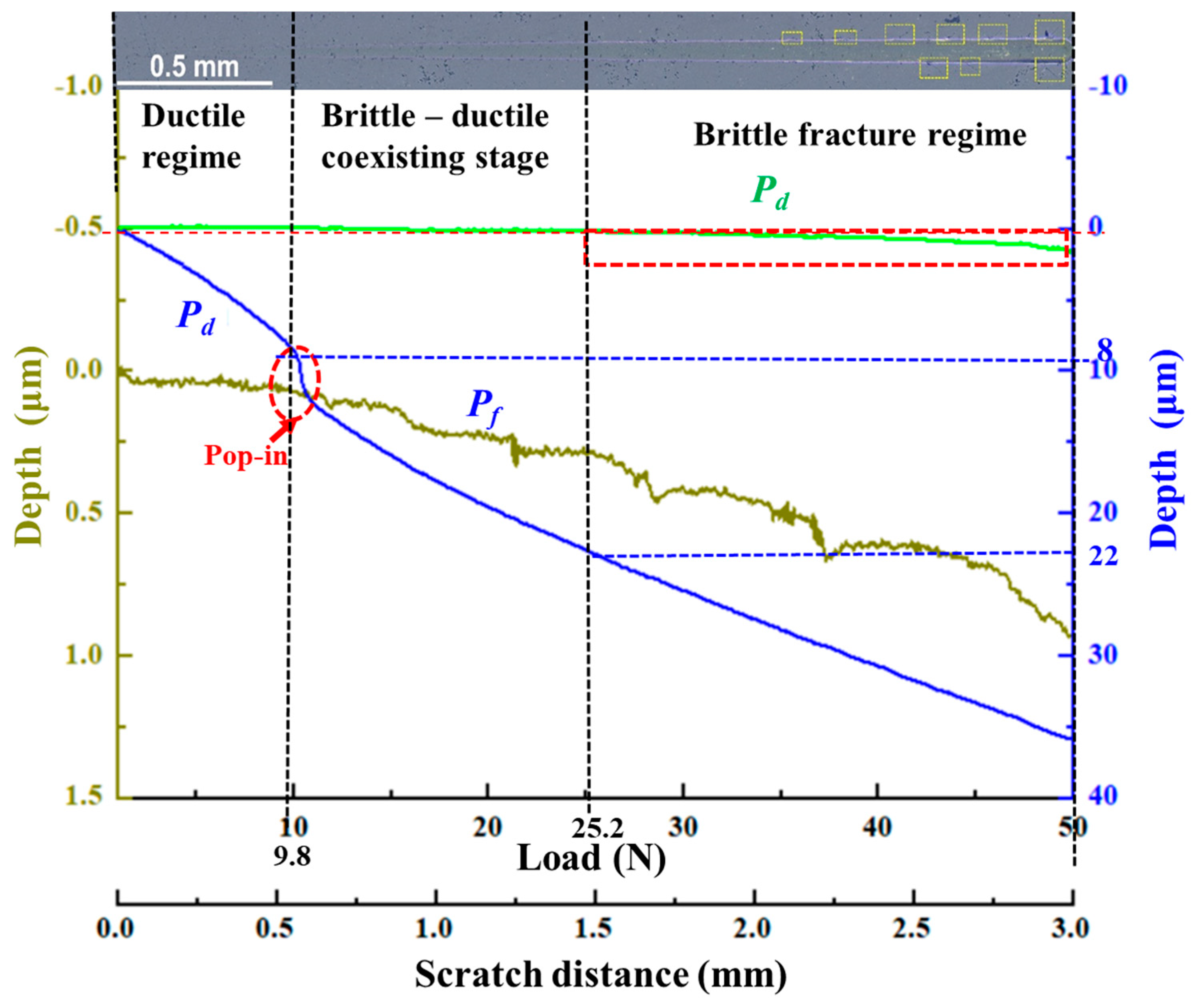
  • Material removal exhibits three stages under increasing scratching depths: the ductile regime, the brittle–ductile coexisting stage, and the brittle fracture regime.
  • When the load is less than 9.8 N, the Si3N4 ceramic material is mainly removed via the ductile material removal process. When the load reaches ~9.8 N, the occurrence of the pop-in event suggests that microcrack initiation and growth have occurred on the subsurface of the Si3N4 sample, and the material removal process transitions from ductile removal to brittle removal.
  • The results show that 9.8 N is the critical value of ductile–brittle removal transformation because of the pop-in event, the critical machined depth of scratching is 8 μm, and the depth of indentation is 3.2 μm under the test conditions employed in this study. Moreover, the critical normal loads and machined depths from our experiments could be applied to identify the different material removal stages in the machining process.

Author Contributions

Conceptualization, X.X., Z.W. and J.D.; methodology, X.X., Q.Y. and H.L.; software and validation, X.X., Q.Y. and H.L.; formal analysis, X.X., Z.W. and Q.X.; investigation, X.X.; writing—original draft preparation, X.X. and J.D.; writing—review and editing, X.X., J.D., Q.X. and Q.Y.; visualization and funding acquisition, Q.Y. and H.L. All authors have read and agreed to the published version of the manuscript.

Funding

This research was funded by the National Natural Science Foundation of China (No. U1801259), and National key R&D plan (No. 2017YFB0310404) and the National Natural Science Foundation of China (51832002, 51775118).

Conflicts of Interest

The authors declare no conflict of interest.

References

  1. Riley, F.L. Silicon nitride and related materials. J. Am. Ceram. Soc. 2000, 83, 245–265. [Google Scholar] [CrossRef]
  2. Kim, T.-W.; Lee, C.M. A study on the development of milling process for silicon nitride using ball end-mill tools by laser-assisted machining. Int. J. Adv. Manuf. Technol. 2015, 77, 1205–1211. [Google Scholar] [CrossRef]
  3. Wan, L.; Liu, Z.; Deng, Z.; Li, L.; Liu, W. Simulation and experimental research on subsurface damage of silicon nitride grinding. Ceram. Int. 2018, 44, 8290–8296. [Google Scholar] [CrossRef]
  4. Wang, Y.; Hadfield, M. Failure modes of ceramic rolling elements with surface crack defects. Wear 2004, 256, 208–219. [Google Scholar] [CrossRef]
  5. Guo, W.; Yuan, J.L.; Xiang, Z. Spheroidal machining test based on variable turning curvature grinding method with single turntable. Surf. Technol. 2018, 47, 251–258. [Google Scholar]
  6. Zhang, B.; Nakajima, A. Dynamics of magnetic fluid support grinding of Si3N4 ceramic balls for ultraprecision bearings and its importance in spherical surface generation. Precis. Eng. J. Int. Soc. Precis. Eng. Nanotechnol. 2003, 27, 1–8. [Google Scholar] [CrossRef]
  7. Umehara, N.; Kirtane, T.; Gerlick, R.; Jain, V.K.; Komanduri, R. A new apparatus for finishing large size/large batch silicon nitride (Si3N4) balls for hybrid bearing applications by magnetic float polishing (MFP). Int. J. Mach. Tools Manuf. 2006, 46, 151–169. [Google Scholar] [CrossRef]
  8. Csanádi, T.; Chinh, N.Q.; Szommer, P.; Dusza, J.; Lenčés, Z.; Šajgalík, P. Deformation and fracture of β-silicon nitride micropillars. J. Am. Ceram. Soc. 2015, 98, 374–377. [Google Scholar] [CrossRef]
  9. Deng, Z.; Zhang, B.; Sun, Z. Study on the materials removal mechanism in ceramic grinding. China Mech. Eng. 2002, 13, 1608–1611. [Google Scholar]
  10. Pei, Z.; Prabhakar, D.; Ferreira, P.; Haselkorn, M. A mechanistic approach to the prediction of material removal rates in rotary ultrasonic machining. J. Eng. Ind. 1995, 117, 771–784. [Google Scholar] [CrossRef] [Green Version]
  11. Cheng, X.; Wei, X.; Yang, X.; Guo, Y. Unified criterion for brittle-ductile transition in mechanical microcutting of brittle materials. J. Manuf. Sci. Eng. 2014, 136, 1013. [Google Scholar] [CrossRef]
  12. Bifano, T.; Dow, T.; Scattergood, R. Ductile-regime grinding. a new technology for machining brittle materials. ASME J. Eng. Ind. 1991, 113, 184–189. [Google Scholar] [CrossRef]
  13. Liu, C. Microstructural and reliability in grinding of silicon nitride. Mater. Sci. Eng. A 2004, 379, 437–442. [Google Scholar] [CrossRef]
  14. Lin, T.; Fu, Y.; Xu, J.; Li, H.; Ding, W. The influence of speed on material removal mechanism in high speed grinding with single grit. Int. J. Mach. Tools Manuf. 2015, 89, 191–201. [Google Scholar]
  15. Axinte, D.; Butler-Smith, P.; Akgun, C.; Kolluru, K. On the influence of single grit micro-geometry on grinding behavior of ductile and brittle materials. Int. J. Mach. Tools Manuf. 2013, 74, 12–18. [Google Scholar] [CrossRef]
  16. Huang, H.; Yin, L.; Zhou, L. High speed grinding of silicon nitride with resin bond diamond wheels. J. Mater. Process. Technol. 2003, 141, 329–336. [Google Scholar] [CrossRef]
  17. Xiao, Q.; Chen, G. Effect of cluster magnetorheological finishing parameters on subsurface damage depth. Acta Photonica Sin. 2017, 47, 69–75. [Google Scholar]
  18. Nazir, M.; Khan, Z.; Saeed, A. Experimental analysis and modelling of c-crack propagation in silicon nitride ball bearing element under rolling contact fatigue. Tribol. Int. 2018, 126, 386–401. [Google Scholar] [CrossRef]
  19. Liu, J.; Lü, S.; Liu, Z. Evaluation of thickness of machined surface deformation layer with image processing technology. J. Tianjin Univ. 2015, 48, 547–554. [Google Scholar]
  20. Xu, L.; Guo, J.; Yu, B.; Qian, L. Rapid detection on the thickness of sub-surface damage layer of silicon. J. Mech. Eng. 2016, 52, 108–114. [Google Scholar] [CrossRef]
  21. Bobzin, K.; Brögelmann, T.; Kruppe, N.; Arghavani, M.; Mayer, J.; Weirich, T. On the ductile deformation of chromium-based nitride hard coatings deposited by hybrid dcMS/HPPMS: A fundamental study using nanoscratch test. Surf. Coat. Technol. 2016, 308, 298–306. [Google Scholar] [CrossRef]
  22. Yan, L.; Jiang, F.; Rong, Y. Grinding mechanism based on single grain cutting simulation. J. Mech. Eng. 2012, 48, 172–182. [Google Scholar] [CrossRef]
  23. Zhang, P.; Zhao, H.; Shi, C.; Zhang, L.; Huang, H.; Ren, L. Influence of double-tip scratch and single-tip scratch on nano-scratching process via molecular dynamics simulation. Appl. Surf. Sci. 2013, 280, 751–756. [Google Scholar] [CrossRef]
  24. Doman, D.; Bauer, R.; Warkentin, A. Experimentally validated finite element model of the rubbing and ploughing phases in scratch tests. Proc. Inst. Mech. Eng. Part B J. Eng. Manuf. 2009, 223, 1519–1527. [Google Scholar] [CrossRef]
  25. Liu, W. Simulation and experiment study for silicon nitride cutting with single diamond grain. J. Mech. Eng. 2015, 51, 191–198. [Google Scholar] [CrossRef]
  26. Liu, W.; Deng, Z.; Shang, Y. Experimental study on single diamond grinding of silicon nitride ceramics. Weapon Mater. Sci. Eng. 2016, 39, 61–65. [Google Scholar]
  27. Zhang, F.; Meng, B.; Geng, Y.; Zhang, Y. Study on the machined depth when nanoscratching on 6H-SiC using Berkovich indenter: Modelling and experimental study. Appl. Surf. Sci. 2016, 368, 449–455. [Google Scholar] [CrossRef]
  28. Wang, J.; Guo, B.; Zhao, Q.; Zhang, C.; Zhang, Q.; Zhai, W. Evolution of material removal modes of sapphire under varied scratching depths. Ceram. Int. 2017, 43, 10353–10360. [Google Scholar] [CrossRef]
  29. Petzow, G.; Herrmann, M. Silicon nitride ceramics. Struct. Bond. 2002, 102, 47–167. [Google Scholar]
  30. Chiang, S. The response of solids to elastic/ductile indentation. II. Fracture initiation. J. Appl. Phys. 1982, 53, 312–317. [Google Scholar] [CrossRef]
  31. Griffith, L. Material Properties and Fracture Mechanics in Relation to Ceramic Machining; U.S. Department of Energy Office of Scientific and Technical Information: Washington, DC, USA, 1993.
  32. Zimmermann, A.; Rödel, J. Fracture statistics based on pore/grain-size interaction. J. Am. Ceram. Soc. 2004, 82, 2279–2281. [Google Scholar] [CrossRef]
  33. Wu, X.; Hong, Y. Microstructure and mechanical properties at TiCp/Ni-alloy interfaces in laser-synthesized coatings. Mater. Sci. Eng. A 2001, 318, 15–21. [Google Scholar] [CrossRef]
  34. Sharma, P.; Yubuta, K.; Kimura, H.; Inoue, A. Brittle metallic glass deforms plastically at room temperature in glassy multilayers. Phys. Rev. B 2009, 80, 024106. [Google Scholar] [CrossRef]
Figure 1. Photos of polished surfaces of silicon nitride ceramic specimens prepared for scratching and indentation experiments.
Micromachines 12 00707 g001
Figure 2. Experimental method: (a) schematic; (b) scratching experiment setup (CSM Revetest Scratch Tester); (c) scratching area; (d) schematic diagram of the curve Pd (the penetration depth of the tip); (e) schematic diagram of the curve Rd (the difference between Pd and residual depth of the scratch track) and mean elastic recovery.
Micromachines 12 00707 g002
Figure 3. Indentation experiments: (a) experiment setup (HXD-2000TM /LCD microhardness tester); (b) specimens after indentation experiments.
Micromachines 12 00707 g003
Figure 4. The Pd, Rd, and Pf curves in the scratching experiment (1–50 N loading).
Micromachines 12 00707 g004
Figure 5. Main load-displacement curves of the scratching experiment (1–50 N loading).
Micromachines 12 00707 g005
Figure 6. SEM micrographs of surface morphology after scratching under an applied load of 1–50 N: (a) full view; (b) ductile regime; (c) brittle–ductile coexisting stage; (d) brittle fracture regime; (e) morphology of pit defects; (f) morphology of fatigue-induced pitting; (g) morphology of pit defects and cracks.
Micromachines 12 00707 g006
Figure 7. Surface morphology of silicon nitride after scratching (SEM) at a 1–10 N loading: (a) full view; (b) ductile removal stage; (c) brittle removal stage; (d) morphology of brittle removal stage.
Micromachines 12 00707 g007
Figure 8. Results of scratching experiment (1–10 N loading): (a) main load–displacement curves; (b) elastic deformation shape.
Micromachines 12 00707 g008
Figure 9. Indentation micrograph and depth curve of Si3N4 material under different loadings: (a) 1.96 N; (b) 2.94 N; (c) 4.9 N; (d) 9.8 N; (e) 19.6 N.
Micromachines 12 00707 g009aMicromachines 12 00707 g009b
Figure 10. Relationship between the indentation depth and load.
Micromachines 12 00707 g010
Table 1. The physical properties of Si3N4. Data from [29].
DensityHardnessElastic ModulusToughnessFlexure Strength
3.22 g/cm318 GPa380 GPa10.5 MPa·m1/2550 MPa
Table 2. The dimensions of Si3N4 specimens for scratching and indentation tests.
LengthWidthThicknessSurface Roughness (Ra)Surface Roughness After Polishing (Ra)
15 mm15 mm0.8 mm404 nm80 nm
Publisher’s Note: MDPI stays neutral with regard to jurisdictional claims in published maps and institutional affiliations.

