
Design, Fabrication, Testing and Simulation of a Rotary Double Comb Drives Actuated Microgripper

 ,
,  ,
,  , , ,
, , ,
Abstract
:1. Introduction
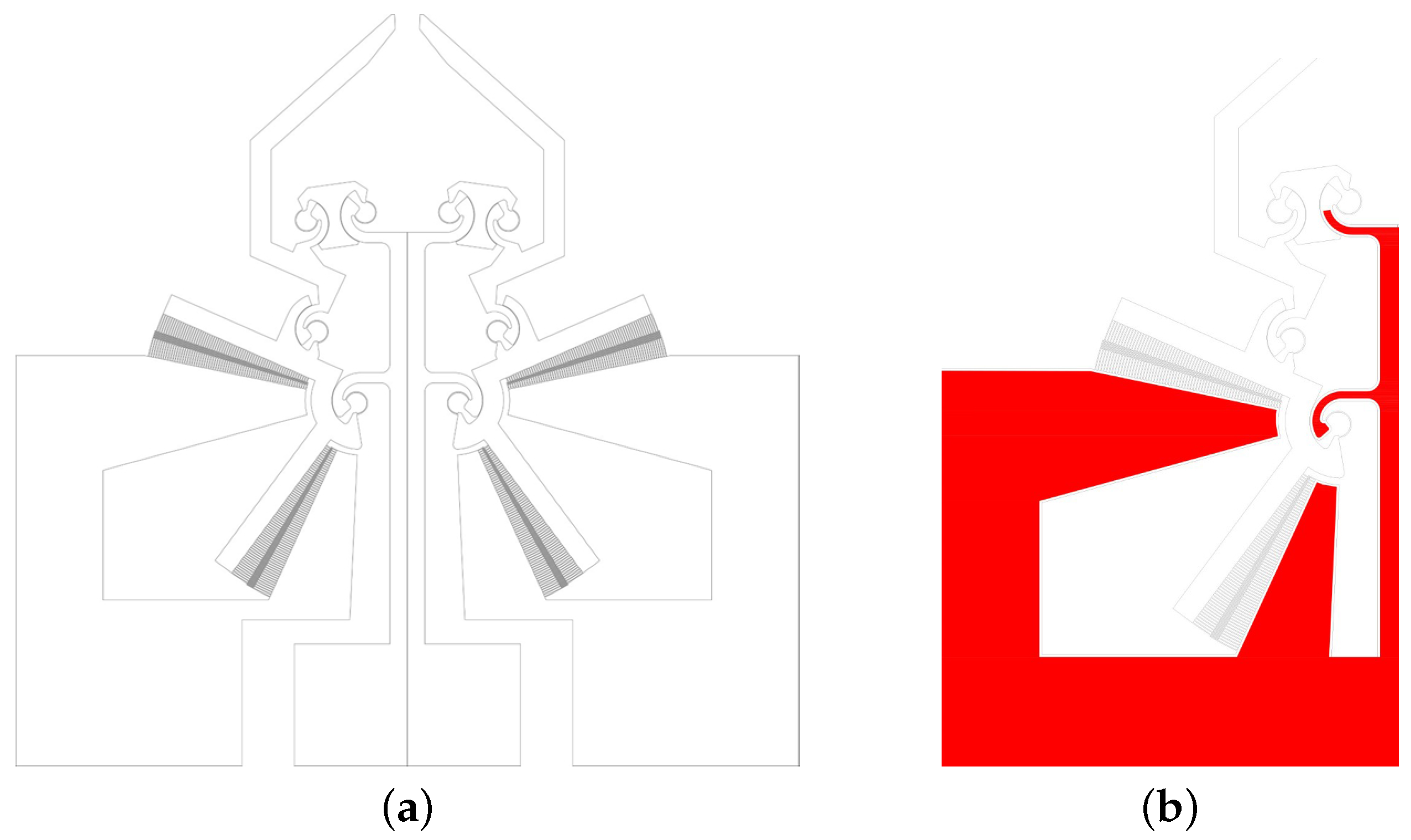
2. Design
- 40 m thick device layer doped to obtain low electrical resistance;
- 3–4 m silicon oxide layer (BOX);
- handle layer with a thickness of 400 m to give a high robustness to the device, which is necessary both for its implementation and its manipulation by the operators.
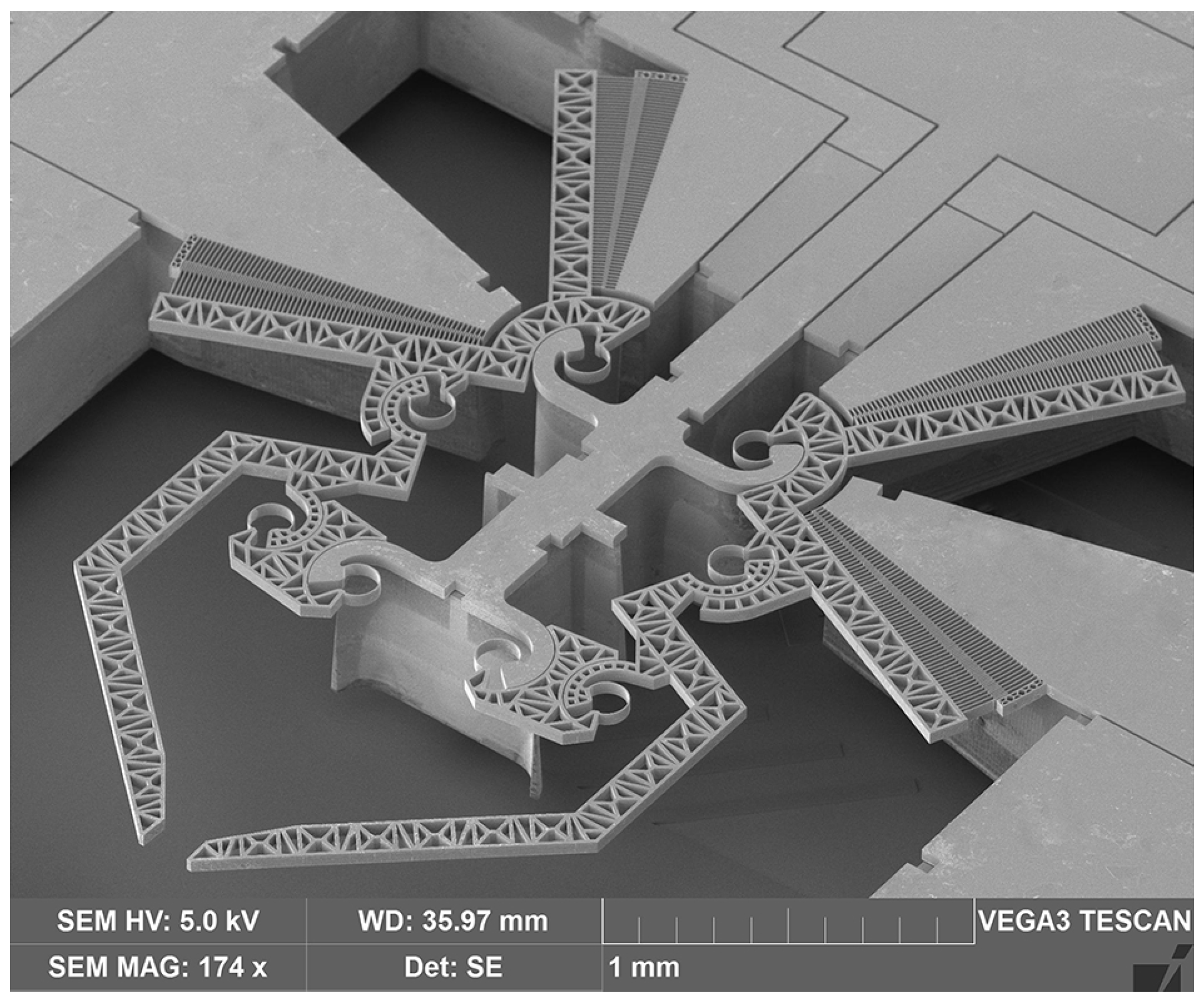
3. Fabrication
4. Testing
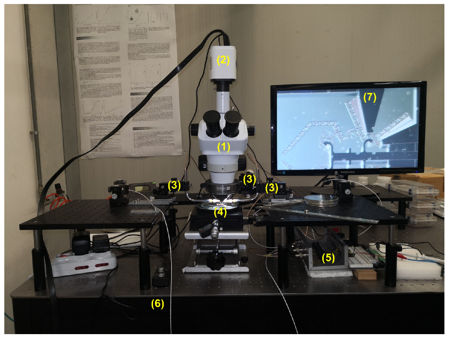
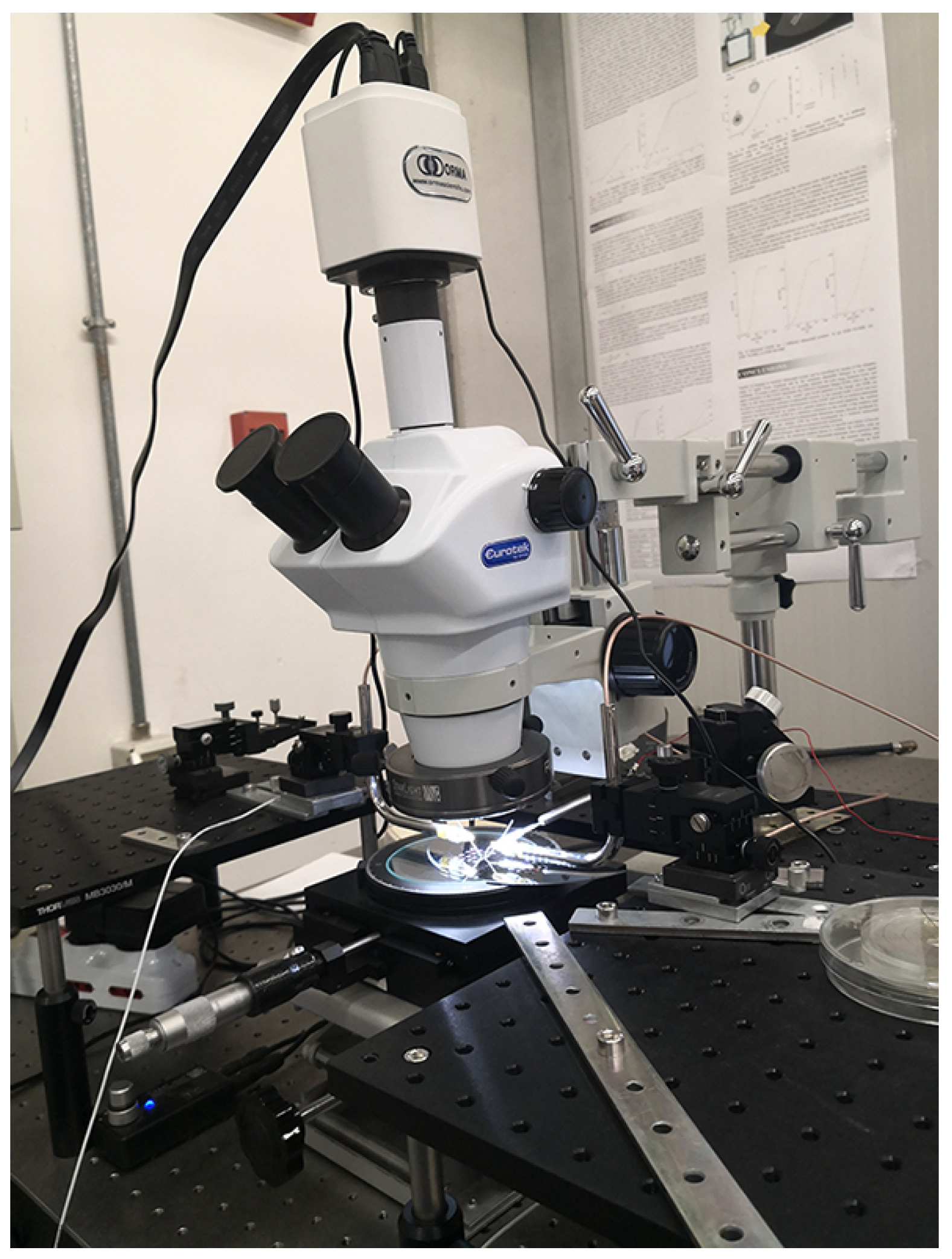
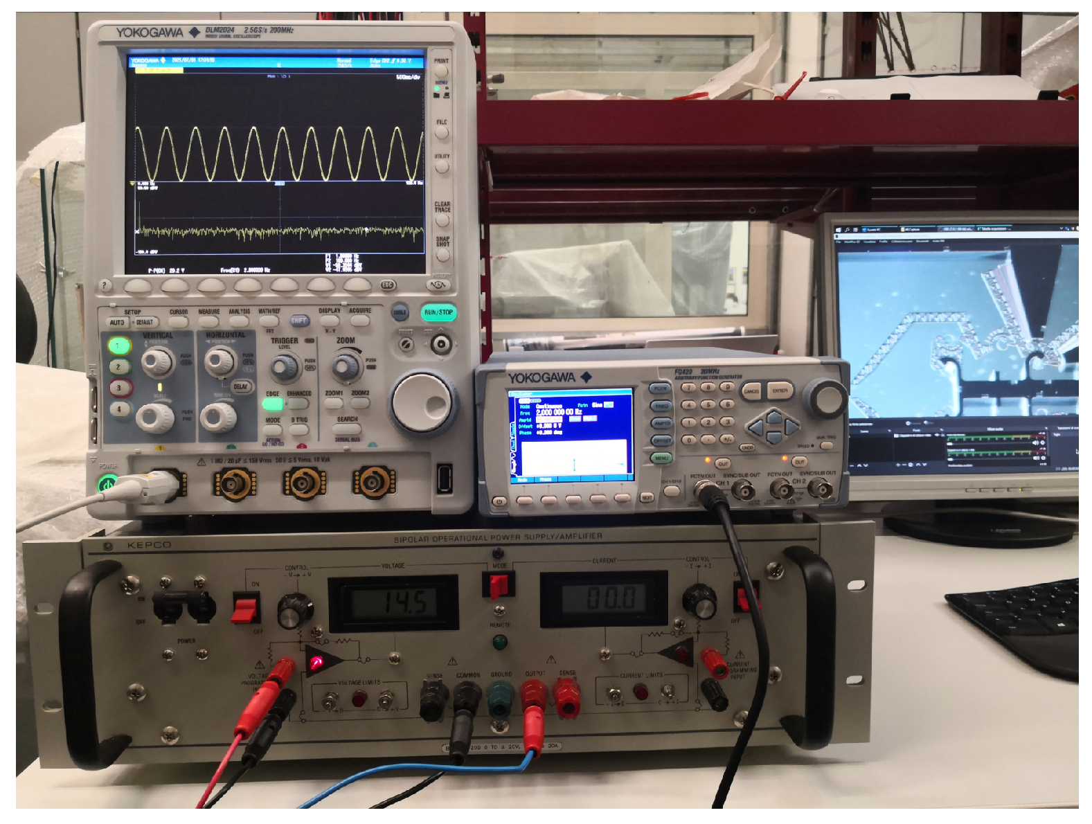
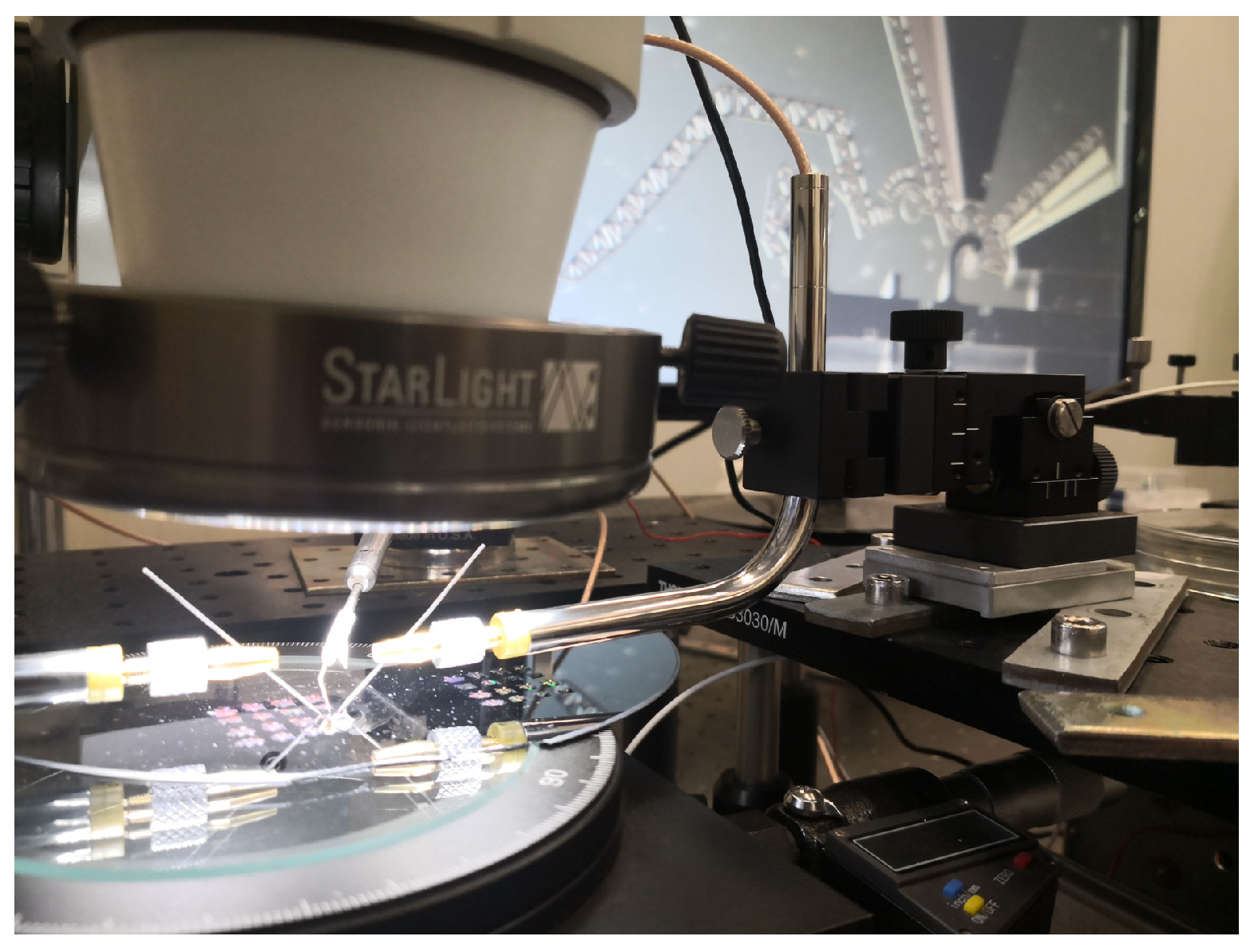
4.1. Experimental Setup
4.2. Video Processing
4.3. Uncertainty Analysis
- Power supply uncertainty on amplitude, , and on frequency, , reported in the datasheet of the function generator.
- Power amplifier uncertainty on amplitude, , reported in the datasheet of the power amplifier.
- Frame time uncertainty, , evaluated assuming that the time difference between adjacent frames is not constant over the time.
- Resolution uncertainty, . Based on [46], it has been assumed an uncertainty on the overall resolution of about 4 m, which, in terms of standard deviation, has been evaluated as 2.3 m, assuming a Gaussian Probability Density Function. This term also takes into account the uncertainty of the optical system, evaluated by considering the lateral resolution that depends on diffraction and the wavelength of the incident light and assumed to be 0.4 m [47].
- Software uncertainty, , also depends on the frequency and the considered quantities (displacement, velocity, and acceleration).
4.4. Comparison between the Simulated and the Experimental Data
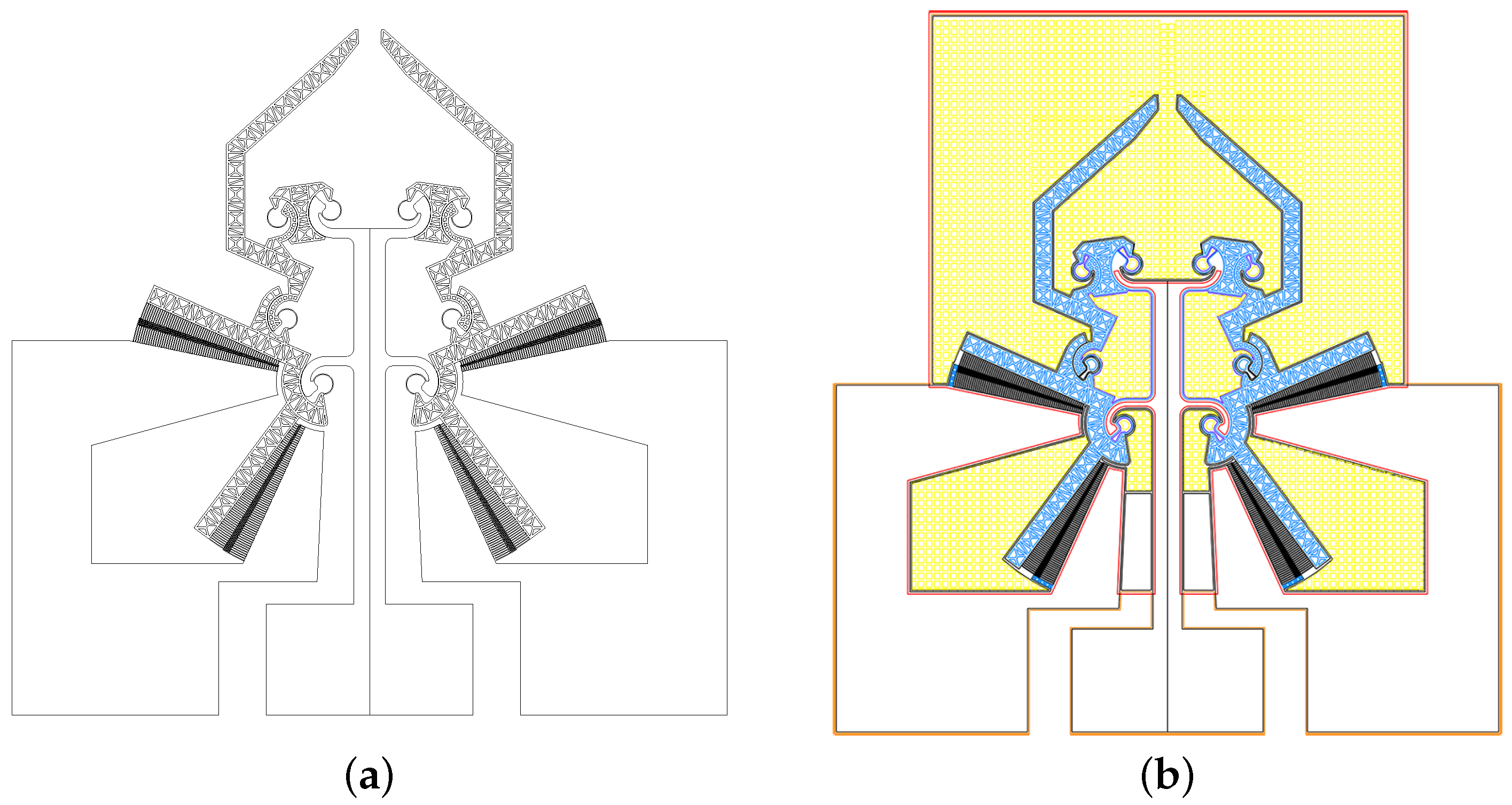
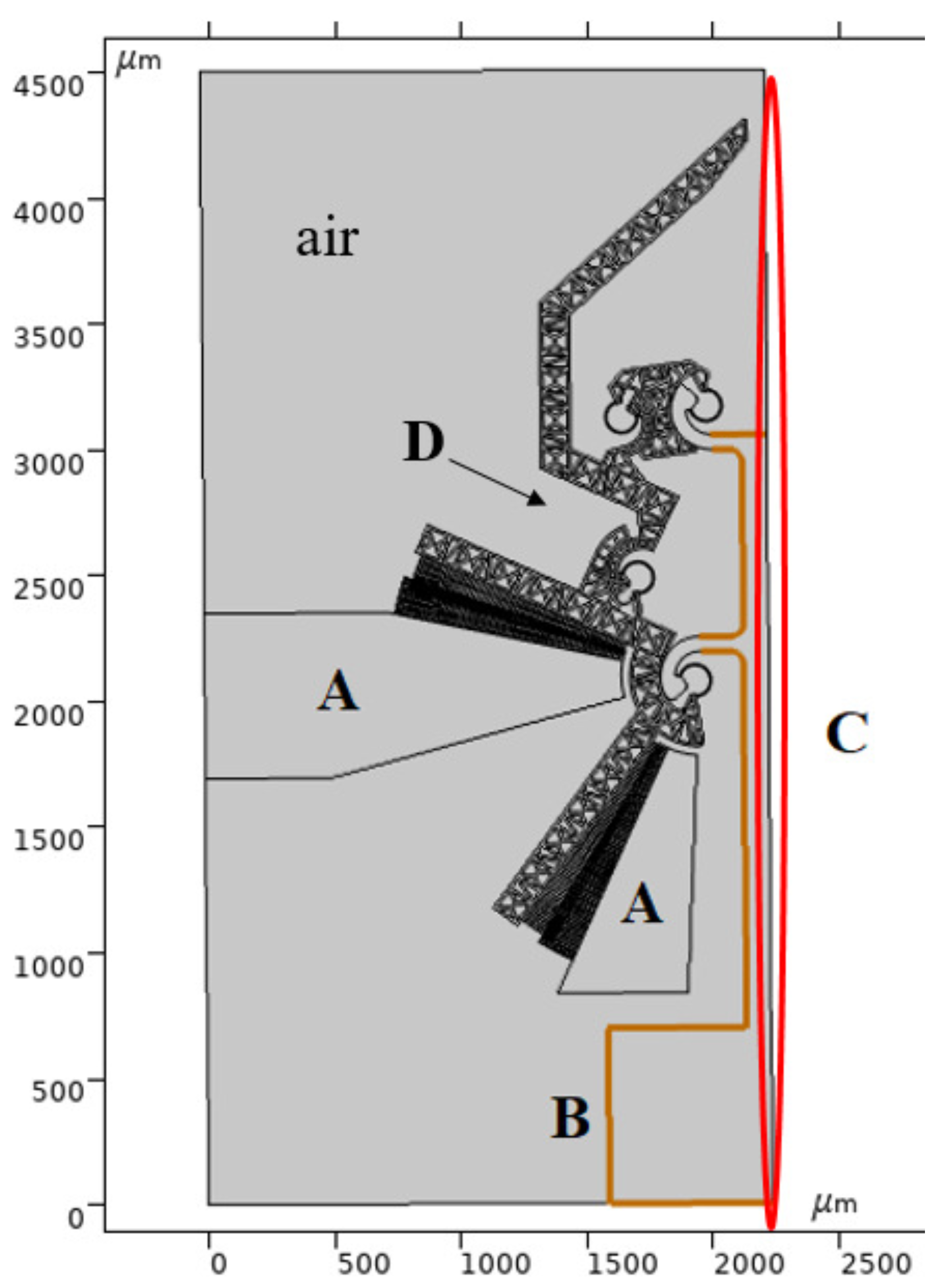
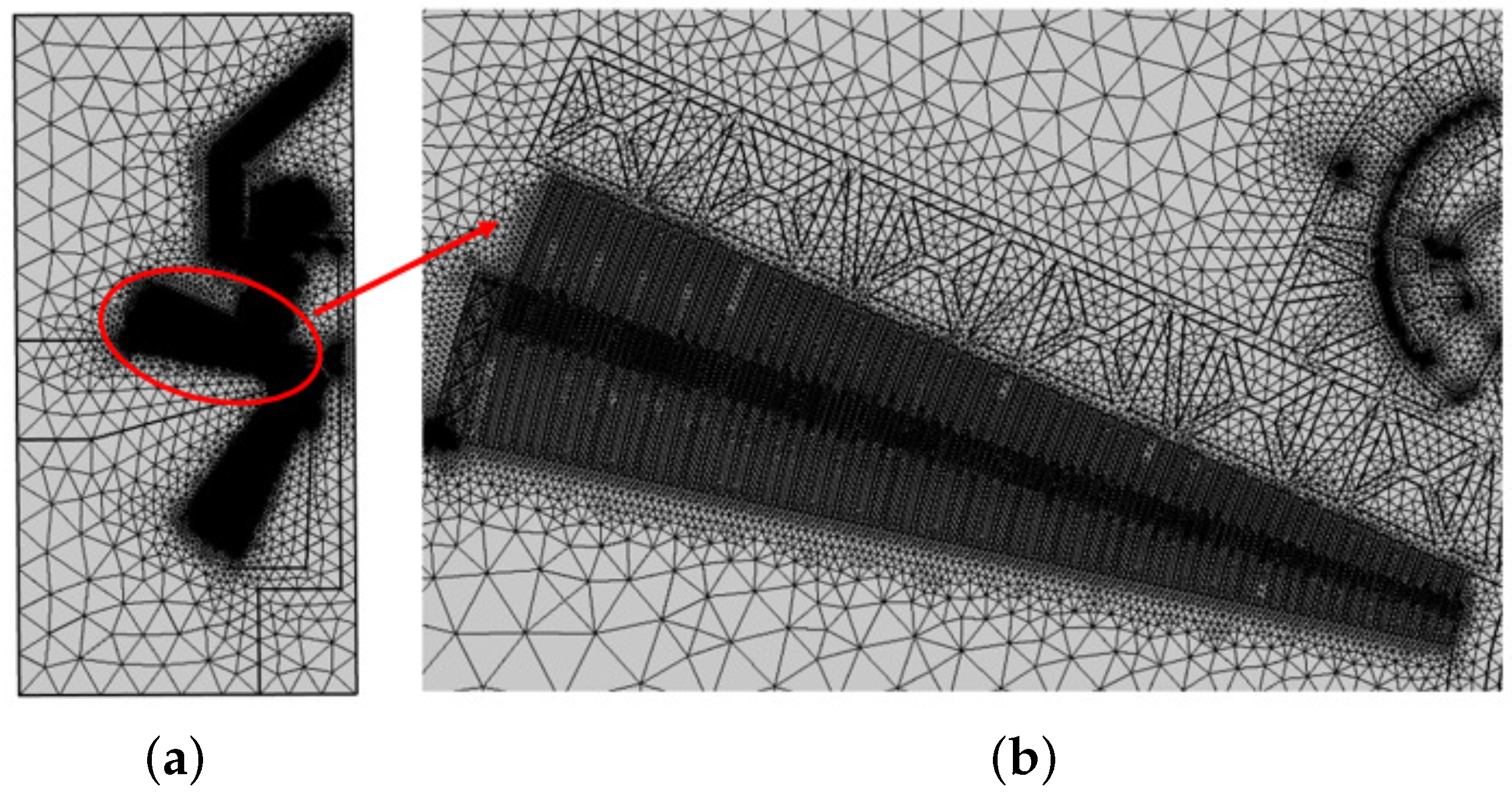
5. Numerical Simulation
- the non-moving fingers are anchored and electrically grounded through the ground pad (A);
- the moving fingers and the remaining gripper parts (D) can move in the plane with respect to the highlighted pad (B);
- the edge (C) represents the symmetric boundary condition.
- the actual microgripper SOI wafer stiffness matrix is unknown because it is a composite material;
- The FEA model considers constant out-of-plane thickness and ideal geometry. On the other hand, each device layer shows non-constant thickness, and geometric imperfection is unavoidable in the actual fabricated microgripper. Therefore, the flexural stiffness of the CSFHs (which mostly impacts the simulations) may randomly vary as a result of the fabrication process;
- the actual device layer presents an aluminum masking that is not considered in FEA.
6. Results and Discussion
7. Conclusions
Author Contributions
Funding
Conflicts of Interest
References
- Cauchi, M.; Grech, I.; Mallia, B.; Mollicone, P.; Sammut, N. The effects of cold arm width and metal deposition on the performance of a U-beam electrothermal MEMS microgripper for biomedical applications. Micromachines 2019, 10, 167. [Google Scholar] [CrossRef] [PubMed] [Green Version]
- Kim, K.; Nilsen, E.; Huang, T.; Kim, A.; Ellis, M.; Skidmore, G.; Lee, J.B. Metallic microgripper with SU-8 adaptor as end-effectors for heterogeneous micro/nano assembly applications. Microsyst. Technol. 2004, 10, 689–693. [Google Scholar] [CrossRef]
- Zeman, M.; Bordatchev, E.; Knopf, G. Design, kinematic modeling and performance testing of an electro-thermally driven microgripper for micromanipulation applications. JMM 2006, 16, 1540–1549. [Google Scholar] [CrossRef] [Green Version]
- Verotti, M.; Dochshanov, A.; Belfiore, N.P. A Comprehensive Survey on Microgrippers Design: Mechanical Structure. J. Mech. Des. Trans. ASME 2017, 139, 060801. [Google Scholar] [CrossRef]
- Grossard, M.; Rotinat-Libersa, C.; Chaillet, N.; Boukallel, M. Mechanical and control-oriented design of a monolithic piezoelectric microgripper using a new topological optimization method. IEEE/ASME Trans. Mechatron. 2009, 14, 32–45. [Google Scholar] [CrossRef]
- Choi, H.S.; Lee, D.C.; Kim, S.S.; Han, C.S. The development of a microgripper with a perturbation-based configuration design method. JMM 2005, 15, 1327–1333. [Google Scholar] [CrossRef]
- Sanò, P.; Verotti, M.; Bosetti, P.; Belfiore, N.P. Kinematic Synthesis of a D-Drive MEMS Device With Rigid-Body Replacement Method. J. Mech. Des. Trans. ASME 2018, 140, 075001. [Google Scholar] [CrossRef]
- Howell, L.L.; Midha, A. A method for the design of compliant mechanisms with small-length flexural pivots. J. Mech. Des. Trans. ASME 1994, 116, 280–290. [Google Scholar] [CrossRef]
- Howell, L.L.; Midha, A.; Norton, T.W. Evaluation of equivalent spring stiffness for use in a pseudo-rigid-body model of large-deflection compliant mechanisms. J. Mech. Des. Trans. ASME 1996, 118, 126–131. [Google Scholar] [CrossRef] [Green Version]
- Belfiore, N.P. Distributed Databases for the development of Mechanisms Topology. Mech. Mach. Theory 2000, 35, 1727–1744. [Google Scholar] [CrossRef]
- Belfiore, N.P. Brief note on the concept of planarity for kinematic chains. Mech. Mach. Theory 2000, 35, 1745–1750. [Google Scholar] [CrossRef]
- Pennestrì, E.; Belfiore, N.P. On the numerical computation of Generalized Burmester Points. Meccanica 1995, 30, 147–153. [Google Scholar] [CrossRef]
- Xu, Q. Design, Fabrication, and Testing of an MEMS Microgripper with Dual-Axis Force Sensor. IEEE Sens. J. 2015, 15, 6017–6026. [Google Scholar] [CrossRef]
- Wierzbicki, R.; Houston, K.; Heerlein, H.; Barth, W.; Debski, T.; Eisinberg, A.; Menciassi, A.; Carrozza, M.; Dario, P. Design and fabrication of an electrostatically driven microgripper for blood vessel manipulation. Microelectron. Eng. 2006, 83, 1651–1654. [Google Scholar] [CrossRef]
- Daly, M.; Pequegnat, A.; Zhou, Y.; Khan, M. Fabrication of a novel laser-processed NiTi shape memory microgripper with enhanced thermomechanical functionality. J. Intell. Mater. Syst. Struct. 2013, 24, 984–990. [Google Scholar] [CrossRef]
- Chu Duc, T.; Lau, G.K.; Sarro, P. Polymeric thermal microactuator with embedded silicon skeleton: Part II- Fabrication, characterization, and application for 2-DOF microgripper. J. Microelectromech. Syst. 2008, 17, 823–831. [Google Scholar] [CrossRef]
- Battocchio, C.; Concolato, S.; De Santis, S.; Fahlman, M.; Iucci, G.; Santi, M.; Sotgiu, G.; Orsini, M. Chitosan functionalization of titanium and Ti6Al4V alloy with chloroacetic acid as linker agent. Mater. Sci. Eng. C 2019, 99, 1133–1140. [Google Scholar] [CrossRef] [PubMed]
- Wang, D.H.; Yang, Q.; Dong, H.M. A monolithic compliant piezoelectric-driven microgripper: Design, modeling, and testing. IEEE/ASME Trans. Mechatron. 2013, 18, 138–147. [Google Scholar] [CrossRef]
- Solano, B.; Wood, D. Design and testing of a polymeric microgripper for cell manipulation. Microelectron. Eng. 2007, 84, 1219–1222. [Google Scholar] [CrossRef]
- Bazaz, S.A.; Khan, F.; Shakoor, R.I. Design, simulation and testing of electrostatic SOI MUMPs based microgripper integrated with capacitive contact sensor. Sens. Actuators A Phys. 2011, 167, 44–53. [Google Scholar] [CrossRef]
- Bharanidaran, R.; Ramesh, T. Numerical simulation and experimental investigation of a topologically optimized compliant microgripper. Sens. Actuators A Phys. 2014, 205, 156–163. [Google Scholar]
- Demaghsi, H.; Mirzajani, H.; Ghavifekr, H.B. Design and simulation of a novel metallic microgripper using vibration to release nano objects actively. Microsyst. Technol. 2014, 20, 65–72. [Google Scholar] [CrossRef]
- Nishimura, T.; Fujihira, Y.; Watanabe, T. Microgripper-embedded fluid fingertip-enhancing positioning and holding abilities for versatile grasping. J. Mech. Robot. 2017, 9, 061017. [Google Scholar] [CrossRef]
- Zhang, J.; Onaizah, O.; Middleton, K.; You, L.; Diller, E. Reliable Grasping of Three-Dimensional Untethered Mobile Magnetic Microgripper for Autonomous Pick-and-Place. IEEE Robot. Autom. Lett. 2017, 2, 835–840. [Google Scholar] [CrossRef]
- Rossi, A.; Orsini, F.; Scorza, A.; Botta, F.; Sciuto, S.A.; Giminiani, R.D. A preliminary characterization of a whole body vibration platform prototype for medical and rehabilitation application. In Proceedings of the IEEE International Symposium on Medical Measurements and Applications (MeMeA), Benevento, Italy, 15–18 May 2016; pp. 1–6. [Google Scholar]
- Orsini, F.; Rossi, A.; Botta, F.; Scorza, A.; Sciuto, S.A.; Marzaroli, P.; Chadefaux, D.; Tarabini, M.; Scalise, L. A case study on the characterization of Whole Body Vibration platforms for medical applications. In Proceedings of the IEEE International Symposium on Medical Measurements and Application (MeMeA), Rome, Italy, 11–13 June 2018. [Google Scholar]
- McClarren, B.; Olabisi, R. Strain and Vibration in Mesenchymal Stem Cells. Int. J. Biomater. 2018, 2018, 1–13. [Google Scholar] [CrossRef] [Green Version]
- Safavi, A.S.; Rouhi, G.; Haghighipour, N.; Bagheri, F.; Eslaminejad, M.B.; Sayahpour, F.A. Efficacy of mechanical vibration in regulating mesenchymal stem cells gene expression. In Vitro Cell. Dev. Biol.-Anim. 2019, 55, 387–394. [Google Scholar] [CrossRef]
- Kanie, K.; Sakai, T.; Imai, Y.; Yoshida, K.; Sugimoto, A.; Makino, H.; Kubo, H.; Kato, R. Effect of mechanical vibration stress in cell culture on human induced pluripotent stem cells. Regen. Ther. 2019, 12, 27–35. [Google Scholar] [CrossRef]
- Anggayasti, W.L.; Imashiro, C.; Kuribara, T.; Totani, K.; Takemura, K. Low-frequency mechanical vibration induces apoptosis of A431 epidermoid carcinoma cells. Eng. Life Sci. 2020, 20, 232–238. [Google Scholar] [CrossRef] [Green Version]
- Verotti, M.; Crescenzi, R.; Balucani, M.; Belfiore, N.P. MEMS-based conjugate surfaces flexure hinge. J. Mech. Des. Trans. ASME 2015, 137, 012301. [Google Scholar] [CrossRef]
- Vurchio, F.; Ursi, P.; Orsini, F.; Scorza, A.; Crescenzi, R.; Sciuto, S.A.; Belfiore, N.P. Toward operations in a surgical scenario: Characterization of a microgripper via light microscopy approach. Appl. Sci. 2019, 9, 1901. [Google Scholar] [CrossRef] [Green Version]
- Cecchi, R.; Verotti, M.; Capata, R.; Dochshanov, A.M.; Broggiato, G.B.; Crescenzi, R.; Balucani, M.; Natali, S.; Razzano, G.; Lucchese, F.; et al. Development of micro-grippers for tissue and cell manipulation with direct morphological comparison. Micromachines 2015, 6, 1710–1728. [Google Scholar] [CrossRef] [Green Version]
- Verotti, M.; Bagolini, A.; Bellutti, P.; Belfiore, N.P. Design and validation of a single-SOI-wafer 4-DOF crawling microgripper. Micromachines 2019, 10, 376. [Google Scholar] [CrossRef] [PubMed] [Green Version]
- Botta, F.; Verotti, M.; Bagolini, A.; Bellutti, P.; Belfiore, N.P. Mechanical response of four-bar linkage microgrippers with bidirectional electrostatic actuation. Actuators 2018, 7, 78. [Google Scholar] [CrossRef] [Green Version]
- Crescenzi, R.; Balucani, M.; Belfiore, N.P. Operational characterization of CSFH MEMS technology based hinges. JMM 2018, 28, 055012. [Google Scholar] [CrossRef]
- Bagolini, A.; Ronchin, S.; Bellutti, P.; Chistè, M.; Verotti, M.; Belfiore, N.P. Fabrication of Novel MEMS Microgrippers by Deep Reactive Ion Etching With Metal Hard Mask. J. Microelectromech. Syst. 2017, 26, 926–934. [Google Scholar] [CrossRef]
- Bagolini, A.; Scauso, P.; Sanguinetti, S.; Bellutti, P. Silicon Deep Reactive Ion Etching with aluminum hard mask. Mater. Res. Express 2019, 6, 085913. [Google Scholar] [CrossRef]
- Orsini, F.; Vurchio, F.; Scorza, A.; Crescenzi, R.; Sciuto, S.A. An image analysis approach to microgrippers displacement measurement and testing. Actuators 2018, 7, 64. [Google Scholar] [CrossRef] [Green Version]
- Vurchio, F.; Orsini, F.; Scorza, A.; Sciuto, S.A. Functional characterization of MEMS Microgripper prototype for biomedical application: Preliminary results. In Proceedings of the 2019 IEEE international symposium on medical measurements and applications (MeMeA), Istanbul, Turkey, 26–28 June 2019; pp. 1–6. [Google Scholar]
- Vurchio, F.; Orsini, F.; Scorza, A.; Fuiano, F.; Sciuto, S.A. A preliminary study on a novel automatic method for angular displacement measurements in microgripper for biomedical applications. In Proceedings of the 2020 IEEE International Symposium on Medical Measurements and Applications (MeMeA), Bari, Italy, 1–3 June 2020; pp. 1–5. [Google Scholar]
- Vurchio, F.; Fiori, G.; Scorza, A.; Sciuto, S.A. A comparison among three different image analysis methods for the displacement measurement in a novel MEMS device. In Proceedings of the 24th IMEKO TC4 International Symposium & 22nd International Workshop on ADC Modelling and DAC Modelling and Testing, Palermo, Italy, 14–16 September 2020. [Google Scholar]
- Vurchio, F.; Fiori, G.; Scorza, A.; Sciuto, S.A. Comparative evaluation of three image analysis methods for angular displacement measurement in a MEMS microgripper prototype: A preliminary study. Acta Imeko 2021, 10, 119–125. [Google Scholar] [CrossRef]
- Vurchio, F.; Bocchetta, G.; Fiori, G.; Scorza, A.; Belfiore, N.P.; Sciuto, S.A. A preliminary study on the dynamic characterization of a MEMS microgripper for biomedical applications. In Proceedings of the 2021 IEEE International Symposium on Medical Measurements and Applications (MeMeA), Neuchâtel, Switzerland, 23–25 June 2021; pp. 1–6. [Google Scholar]
- Shi, J.; Tomasi. Good features to track. In Proceedings of the 1994 IEEE Conference on Computer Vision and Pattern Recognition, Seattle, WA, USA, 21–23 June 1994; pp. 593–600. [Google Scholar]
- Brown, L. Imaging Particle Analysis: Resolution and Sampling Considerations; Fluid Imaging Technologies, Inc.: Scarborough, ME, USA, 2009; Available online: https://info.fluidimaging.com/hs-fs/hub/300163/file-657139900-pdf/white-papers/imaging-particle-analysis-analysis-resolution-sampling-considerations.pdf (accessed on 17 September 2021).
- Prasad, B. Introduction to Biophotonics; John Wiley & Sons, Inc.: Hoboken, NJ, USA, 2003. [Google Scholar]
- ISO/IEC. Part 3: Guide to the expression of uncertainty in measurement (GUM:1995). In Guide 98-3: 2008, Uncertainty of Measurement; ISO/IEC: Geneva, Switzerland, 2008. [Google Scholar]
- Hopcroft, M.A.; Nix, W.D.; Kenny, T.W. What is the Young’s Modulus of Silicon? J. Microelectromech. Syst. 2010, 19, 229–238. [Google Scholar] [CrossRef] [Green Version]
- MEMSNet, MEMS and Nanotechnology Clearinghouse, Reston, Virginia, USA. Available online: https://www.memsnet.org/material/siliconsibulk/ (accessed on 17 September 2021).


| Component | Label | Value |
|---|---|---|
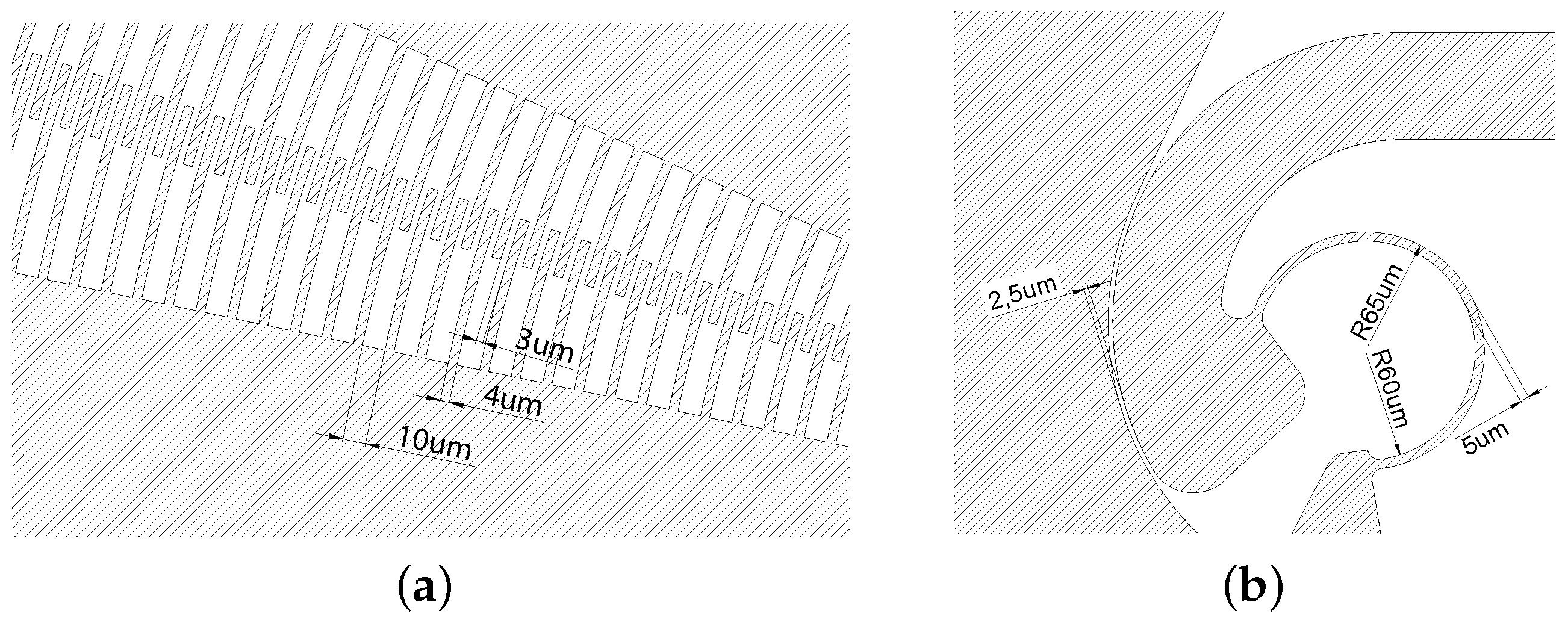
| Finger | Width | 4 m |
| Min length | 38 m | |
| Max length | 151 m | |
| Thickness | 40 m | |
| Distance | 10 m | |
| Finger clearance | 3 m | |
| Overlapping | Initial angle | 2 |
| Rotor-Stator finger distance | 3 m | |
| SOI Wafer | Device layer thickness | 40 m |
| Buried oxide layer | 5 m | |
| Handle layer | 400 m | |
| CSFH | Curved beam length | 252 m |
| Curved beam width | 5 m | |
| Curved beam thickness | 40 m | |
| Curvature radius | 62.5 m | |
| Conjugate surfaces clearance | 2.5 m |
| Device | Characteristics |
|---|---|
| Silicon microgripper, device thickness 40 m, | |
| Device Under Test (DUT) | insulated layer thickness 3 m, handle thickness 400 m, |
| capacitive Comb-Drives. | |
| YOKOGAWA FG420 | |
| Amplitude: Setting range: 0 to 10 V, | |
| Function Generator | Resolution: 36 mV, |
| Accuracy: ±1% of amplitude setting [V] + 2 mV | |
| KEPCO BOP 20-20D | |
| Power Amplifier | Output: 0 to ±20 V, Accuracy: ±2 mV |
| n.1 MP25L, n.1 MP25R, | |
| Micropositioner | range X/Y/Z 10/10/10 mm |
| with 5 m resolution | |
| Probes (supply) | PA-C-1M with tungsten needles |
| NB50TS, zoom range 0.8× 5× (8×–50×), | |
| Light Microscope | LED illumination Transmitted-Reflected, |
| B2-1525 additional objective 2× | |
| Digital Camera | MD6iS, 6MP, pixel dimension, 2.8 m × 2.8 m, |
| maximum resolution 3264 × 1840 px | |
| Image Processing Software | In-house software developed in MATLAB environment |
| (2020b, MathWorks) | |
| AMD Ryzen 5 3500U | |
| PC | with Radeon Vega Mobile Gfx 2.10 GHz, |
| 8.00 GB RAM |
| Source | Value |
|---|---|
| Power supply uncertainty on amplitude | 1% of [V] + 2 mV |
| Power supply uncertainty on frequency | 0.01 Hz |
| Power amplifier uncertainty | 2 mV |
| Frame time uncertainty | 1 ms |
| Resolution uncertainty | 2.3 m |
| it depends on frequency, | |
| as well as on considered quantities | |
| Software uncertainty | (displacement, velocity, and acceleration) |
| and on every time instant | |
| of the output signal. |
| Maximum Value | Angular Displacement (rad) | Angular Velocity (rad/s) | Angular Acceleration (rad/s2) |
|---|---|---|---|
| 0.5 Hz | |||
| 1.0 Hz | |||
| 1.5 Hz | |||
| 2.0 Hz | |||
| 3.0 Hz | |||
| 4.0 Hz |
| Frequency | Angular Displacement (rad) | Angular Velocity (rad/s) | Angular Acceleration (rad/s2) |
|---|---|---|---|
| 0.5 Hz | <1% | <1% | <3% |
| 1.0 Hz | <1% | <1.4% | <2% |
| 1.5 Hz | <1% | <1% | <1.5% |
| 2.0 Hz | <1% | <1.6% | <0.8% |
| 3.0 Hz | <1% | <0.8% | <0.5% |
| 4.0 Hz | <1% | <0.6% | <0.5% |
| Frequency | Displacement | Velocity | Acceleration |
|---|---|---|---|
| 4.0 Hz | <1% | <1% | <1% |
Publisher’s Note: MDPI stays neutral with regard to jurisdictional claims in published maps and institutional affiliations. |
© 2021 by the authors. Licensee MDPI, Basel, Switzerland. This article is an open access article distributed under the terms and conditions of the Creative Commons Attribution (CC BY) license (https://creativecommons.org/licenses/by/4.0/).
Share and Cite
Belfiore, N.P.; Bagolini, A.; Rossi, A.; Bocchetta, G.; Vurchio, F.; Crescenzi, R.; Scorza, A.; Bellutti, P.; Sciuto, S.A. Design, Fabrication, Testing and Simulation of a Rotary Double Comb Drives Actuated Microgripper. Micromachines 2021, 12, 1263. https://doi.org/10.3390/mi12101263
Belfiore NP, Bagolini A, Rossi A, Bocchetta G, Vurchio F, Crescenzi R, Scorza A, Bellutti P, Sciuto SA. Design, Fabrication, Testing and Simulation of a Rotary Double Comb Drives Actuated Microgripper. Micromachines. 2021; 12(10):1263. https://doi.org/10.3390/mi12101263
Chicago/Turabian StyleBelfiore, Nicola Pio, Alvise Bagolini, Andrea Rossi, Gabriele Bocchetta, Federica Vurchio, Rocco Crescenzi, Andrea Scorza, Pierluigi Bellutti, and Salvatore Andrea Sciuto. 2021. "Design, Fabrication, Testing and Simulation of a Rotary Double Comb Drives Actuated Microgripper" Micromachines 12, no. 10: 1263. https://doi.org/10.3390/mi12101263