Built-In Self-Test (BIST) Methods for MEMS: A Review


Abstract
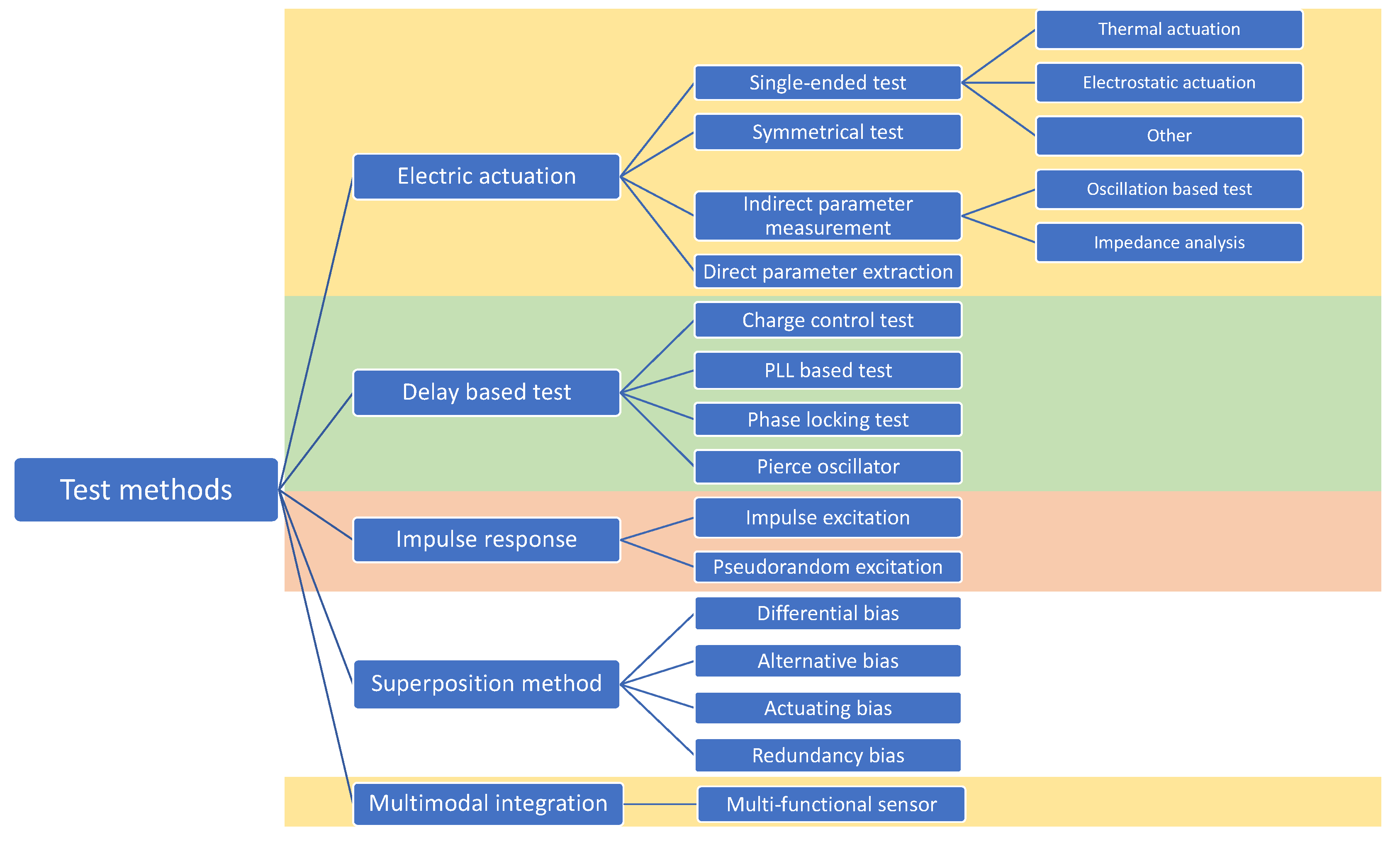
:1. Introduction
2. Electrically Induced Stimuli Test
2.1. Single-Ended Test
2.1.1. Electrostatic Actuation
2.1.2. Thermal Actuation
2.1.3. Other Thermally Induced Effects
2.2. Symmetrical Test Method
2.3. Direct Parameter Extraction Test
2.4. Indirect Parameter Extraction Test
2.4.1. Oscillation-Based Test
2.4.2. Impedance Analysis
2.5. Discussion
3. Delay-Based Test Methods
3.1. Charge Control Technique
3.2. PLL Based Built-in Self-Test (BIST)
3.3. Phase Locking Test Method
3.4. Pierce Oscillator
3.5. Discussion
4. Impulse Response Test Method
4.1. Pulse Excitation Test Method
4.2. Pseudorandom Test Method
4.3. Discussion
5. Bias Superposition/Modulation Method
5.1. Differential Bias
5.2. Alternative Bias
5.3. Actuating Bias
5.4. Redundancy Bias
5.5. Discussion
6. BIST Method Building on Multi-Functional Sensors
7. Classification and Benchmarking of the BIST Methods
7.1. Benchmarking Methodology of the BIST Methods
7.1.1. Ease of Implementation
7.1.2. Usefulness
7.1.3. Test Duration
7.1.4. Power Consumption
7.2. Classification of the BIST Methods
7.2.1. Field Test
7.2.2. Power-On Test
7.2.3. Assembly Phase Test
8. General Conclusions
Author Contributions
Funding
Conflicts of Interest
Abbreviations
| AC | Alternating Current |
| ATPG | Automatic Test Pattern Generation |
| BISR | Built-In Self-Repair |
| BIST | Built-In Self-Test |
| CMOS | Complementary Metal-Oxide-Semiconductor |
| CRC | Cyclic Redundancy Check |
| DC | Direct Current |
| DDM | Delay Detection Module |
| DLL | Delay Locked Loop |
| DUT | Device Under Test |
| EOL | End of Life |
| HABIST | Histogram-Based Analog BIST |
| HVCP | High Voltage Charge Pump |
| IC | Integrated Circuit |
| IR | Impulse Response |
| JTAG | Joint Test Action Group |
| LBIST | Logic BIST |
| LIRMM | Laboratoire d’Informatique, de Robotique et de Microélectronique de Montpellier |
| LFSR | Linear Feedback Shift Register |
| LTI | Linear Time Invariant |
| MBIST | Memory BIST |
| MBISR | Memory Built-In Self-Repair |
| MEMS | Micro-Electro-Mechanical Systems |
| MFS | Multi-Functional Sensor |
| MLS | Maximum Length Sequence |
| OTM | Oscillation-Based Test Method |
| PBIST | Programmable BIST |
| PE | Pulse Extraction |
| PFD | Phase-Frequency-Detector |
| PVT | Process, Supply Voltage and Temperature |
| PLL | Phase-Locked Loop |
| PRPG | Pseudo-Random Pattern Generator |
| RF | Radio Frequency |
| RUL | Remaining Useful Life |
| SNR | Signal-to-Noise Ratio |
| TDC | Time-to-Digital Converter |
| TSMC | Taiwan Semiconductor Manufacturing Company |
| VCO | Voltage-Controlled Oscillator |
References
- Balavalad, K.B.; Sheeparamatti, B.G. A Critical Review of MEMS Capacitive Pressure Sensors. Sens. Transducers J. 2015, 187, 120–128. [Google Scholar]
- Salomon, P.; Bazu, M.; van Heeren, H.; Lavu, S.; Bunyan, J.; Desmulliez, M. The reliability of micro nano systems. Int. Mag. Smart Syst. Technol. MST/NEWS 2008, 4, 20–22. [Google Scholar]
- Lavu, S.; Desmulliez, M.; Begbie, M.; Ball, G.; de Wolf, I. Avoiding MEMS failures. IEE Electron. Syst. Softw. 2005, 3, 22–25. [Google Scholar] [CrossRef]
- Moyer, B. The MEMS Testing Quagmire. 2011. Available online: https://www.eejournal.com/article/20111219-mems/ (accessed on 12 July 2020).
- Lawes, R.A. MEMS Cost Analysis: From Laboratory to Industry; CRC Press: New York, NY, USA, 2014. [Google Scholar]
- Analysis of MEMS Test Equipment Market. 2008. Available online: https://www.fierceelectronics.com/components/analysis-mems-test-equipment-market (accessed on 12 July 2020).
- Allen, H.V.; Terry, S.C.; de Bruin, D.W. Self-Testable Accelerometer Systems. In IEEE Micro Electro Mechanical Systems, Proceedings, An Investigation of Micro Structures, Sensors, Actuators, Machines and Robots, Salt Lake City, UT, USA, 20–22 February 1989; IEEE: Piscataway, NJ, USA, 2002; Volume 20, pp. 153–161. [Google Scholar] [CrossRef]
- Stroud, C.E. A Designer’s Guide to Built-In Self-Test; Kluwer Academic Publishers: Norwell, MA, USA, 2002; Volume 19. [Google Scholar]
- Benso, A.; Chinsano, S.; di Natale, G.; Prinetto, P.; Bodoni, M.L. Online and offline BIST in IP-core design. IEEE Des. Test Comput. 2001, 18, 92–99. [Google Scholar] [CrossRef]
- Frohwerk, R.A. Signature Analysis: A New Digital Field. Hewlett Packard J. 1998, 2–8. Available online: https://doc.xdevs.com/docs/HP_Agilent_Keysight/journals/HP%20Journal%20-%20Signature%20Analysis%20May77.pdf (accessed on 12 July 2020).
- McCluskey, E. Built-In Self-Test Techniques. IEEE Des. Test Comput. 1985, 2, 21–28. [Google Scholar] [CrossRef]
- Frisch, A.; Almy, T. HABIST: Histogram-Based Analog Built in Self Test. In Proceedings International Test Conference 1997, Washington, DC, USA, 6 November 1997; IEEE: Piscataway, NJ, USA, 1997; pp. 760–767. [Google Scholar]
- Wang, L. Logic Built-In Self-Test. In VLSI Test Principles and Architectures; Morgan Kaufmann: Burlington, MA, USA, 2006; pp. 263–340. [Google Scholar]
- Masnita, M.I.; Zuha, W.H.W.; Sidek, R.M.; Halin, I.A. The Data and Read/Write Controller for March-Based SRAM Diagnostic Algorithm MBIST. In Proceedings 2009 IEEE Student Conference on Research and Development (SCOReD), Serdang, Malaysia, 16–18 November 2009; IEEE: Piscataway, NJ, USA, 2009; pp. 296–299. [Google Scholar] [CrossRef]
- Subir, K.R. Integration Verification in System on Chips Using Formal Techniques Micro Electron. Mech. Syst. 2009, 405–430. [Google Scholar] [CrossRef]
- Wehage, E. Built-in Self Test Parallel JTAG Serial Chain Architecture for Reduced Test Vector Size. U.S. Patent Application No. 2003/0172333/A1, 11 September 2003. [Google Scholar]
- Das, D.; Touba, N.A. Reducing Test Data Volume Using External/LBIST hybrid Test Patterns. In Proceedings of the International Test Conference 2000 (IEEE Cat. No.00CH37159), Atlantic City, NJ, USA, 3–5 October 2000; IEEE: Piscataway, NJ, USA, 2000. [Google Scholar] [CrossRef]
- Block, S.G.; Rueveni, D.R. Logic Built-In Self Test (Bist). U.S. Patent Application No. 6,904,554 B2, 4 December 2005. [Google Scholar]
- Li, N.; Carlsson, G.; Dubrova, E.; Petersen, K. Logic BIST: State-of-the-Art and Open Problems. arXiv 2015, arXiv:1503.04628. [Google Scholar]
- Acharya, G.P.; Rani, M.A. Survey of Test Strategies for System-on Chip and It’s Embedded Memories. In Proceedings of the 2013 IEEE Recent Advances in Intelligent Computational Systems (RAICS), Trivandrum, India, 19–21 December 2013; IEEE: Piscataway, NJ, USA, 2013; pp. 199–204. [Google Scholar] [CrossRef]
- Zorian, Y.; Shoukourian, S. Embedded-memory test and repair: Infrastructure IP for SoC yield. IEEE Des. Test Comput. 2003, 20, 1198687. [Google Scholar] [CrossRef]
- Benso, A.; Chiusano, S.; di Natale, G.; Prinetto, P. An on-line BIST RAM architecture with self-repair capabilities. IEEE Trans. Reliab. 2002, 51, 123–128. [Google Scholar] [CrossRef]
- Charlot, B.; Mir, S.; Parrain, F.; Courtois, B. Electrically Induced Stimuli for MEMS Self-Test. In Proceedings of the 19th IEEE VLSI Test Symposium. VTS 2001, Marina Del Rey, CA, USA, 29 April–3 May 2001; IEEE: Piscataway, NJ, USA, 2002; pp. 210–215. [Google Scholar] [CrossRef]
- Charlot, B.; Mir, S.; Parrain, F.; Courtois, B. Generation of electrically induced stimuli for MEMS self-test. J. Electron. Test 2001, 17, 459–470. [Google Scholar] [CrossRef]
- Mir, S.; Rufer, L.; Dhayni, A. Built-in-self-test techniques for MEMS. Microelectron. J. 2006, 37, 591–1597. [Google Scholar] [CrossRef]
- Analog Devices, Monolithic Accelerometer with Signal Conditioning. In ADXL50 Tech Note; Analog Devices Inc.: Norwood, MA, USA, 1996.
- Puers, R.; Reyntjens, S.; Bruyker, D.D. Remote Sensors with Self-Test: New Opportunities to Improve the Performance of Physical Transducers. Adv. Eng. Mater. 2001, 3, 788–795. [Google Scholar] [CrossRef]
- Lapadatu, A.C.; de Bruyker, D.; Jakobsen, H.; Puers, R. A new concept for a self-testable pressure sensor based on the bimetal effect. Sens. Actuators Phys. 2000, 82, 69–73. [Google Scholar] [CrossRef]
- Charlot, B.; Parrain, F.; Mir, S.; Courtois, B. Self-Testable CMOS Thermopile-Based Infrared Imager. In Design, Test, Integration, and Packaging of MEMS/MOEMS 2001, Cannes-Mandelieu, France, 25–27 April 2001; Society of Photo-Optical Instrumentation Engineers: Bellingham, WA, USA, 2001; pp. 96–103. [Google Scholar] [CrossRef]
- Ozel, M.K.; Cheperak, M.; Dar, T.; Kiaei, S.; Bakkaloglu, B.; Ozev, S. An Electrical-Stimulus-Only BIST IC for Capacitive MEMS Accelerometer Sensitivity Characterization. IEEE Sens. J. 2017, 17, 695–708. [Google Scholar] [CrossRef] [Green Version]
- Zimmermann, L.; Ebersohl, J.P.; le Hung, F.; Berry, J.P.; Baillieu, F.; Rey, P.; Diem, B.; Renard, S.; Caillat, P. Airbag application: A microsystem including a silicon capacitive accelerometer, CMOS switched capacitor electronics and true self-test capability. Sens. Actuators Phys. 1995, 46, 190–195. [Google Scholar] [CrossRef]
- Deb, N.; Blanton, R.D.S. High-Level Fault Modeling in Surface-Micromachined MEMS. In Proceedings of the SPIE 4019, Design, Test, Integration, and Packaging of MEMS/MOEMS, Paris, France, 9–11 May 2000; Society of Photo-Optical Instrumentation Engineers: Bellingham, WA, USA, 2000; pp. 228–235. [Google Scholar] [CrossRef]
- Deb, N.; Blanton, R.S. High-level fault modeling in surface-micromachined MEMS. Analog Integr. Circuits Signal Process. 2001, 29, 151–158. [Google Scholar] [CrossRef]
- Muratet, S.; Fourniols, J.-Y.; Soto-Romero, G.; Endemaño, A.; Marty, A.; Desmulliez, M. MEMS reliability modelling methodology: Application to wobble micromotor failure analysis. Microelectron. Reliab. 2003, 43, 1945–1949. [Google Scholar] [CrossRef]
- Muratet, S.; Lavu, S.; Fourniols, J.Y.; Bell, G.; Desmulliez, M.P.Y. Reliability modelling and analysis of thermal MEMS. J. Phys. Conf. Ser. 2006, 34, 235–240. [Google Scholar] [CrossRef]
- de Bruyker, D.; Cozma, A.; Puers, R. A combined piezoresistive/capacitive pressure sensor with self-test function based on thermal actuation. Sens. Actuators Phys. 1998, 66, 70–75. [Google Scholar] [CrossRef]
- Deb, N.; Blanton, R.D. Built-In Self Test Of MEMS. U.S. Patent Application No. 2004/0113647/A1, 17 June 2014. [Google Scholar]
- Deb, N.; Blanton, R.D. Built-in Self Test of CMOS-MEMS Accelerometers. In Proceedings of the IEEE International Test Conference, Baltimore, MD, USA, 7–10 October 2002; IEEE: Piscataway, NJ, USA, 2002; pp. 1075–1084. [Google Scholar] [CrossRef]
- Deb, N.; Blanton, R.D. Built-In Self-Test of MEMS Accelerometers. J. Microelectromechanical Syst. 2006, 15, 52–68. [Google Scholar] [CrossRef]
- Deb, N.; Blanton, R.D. Multi-Modal Built-in Self-Test for Symmetric Microsystems. In Proceedings of the 22nd IEEE VLSI Test Symposium, 2004. Proceedings, Napa Valley, CA, USA, 25–29 April 2004; IEEE: Piscataway, NJ, USA, 2004; pp. 139–147. [Google Scholar] [CrossRef]
- Xiong, X.; Wu, Y.-L.; Jone, W.-B. A Dual-Mode Built-in Self-Test Technique for Capacitive MEMS Devices. In Proceedings of the 22nd IEEE VLSI Test Symposium, 2004. Proceedings, Napa Valley, CA, USA, 25–29 April 2004; IEEE: Piscataway, NJ, USA, 2004; pp. 148–153. [Google Scholar] [CrossRef]
- Xiong, X.; Wu, Y.-L.; Jone, W.-B. A dual-mode built-in self-test technique for capacitive MEMS device. IEEE Trans. Instrum. Meas. 2005, 54, 1739–1750. [Google Scholar] [CrossRef]
- Natarajan, V.; Bhattacharya, S.; Chatterjee, A. Alternate Electrical Tests for Extracting Mechanical Parameters of MEMS Accelerometer Sensors. In Proceedings of the 24th IEEE VLSI Test Symposium, Berkeley, CA, USA, 30 April–4 May 2006; IEEE: Piscataway, NJ, USA, 2006; pp. 192–199. [Google Scholar] [CrossRef]
- Friedman, J.H. Multivariate adaptive regression splines. Ann. Stat. 1991, 19, 1–67. [Google Scholar] [CrossRef]
- Variyam, P.N.; Cherubal, S.; Chatterjee, A. Prediction of analog performance parameters using fast transient testing. IEEE Trans. Comput. Aided Des. Integr. Circuits Syst. 2002, 21, 349–361. [Google Scholar] [CrossRef] [Green Version]
- Han, D.; Chatterjee, A. Robust Built-In Test of RF ICs Using Envelope Detectors. In Proceedings of the 14th Asian Test Symposium (ATS’05), Calcutta, India, 18–21 December 2005; IEEE: Piscataway, NJ, USA, 2005; pp. 2–7. [Google Scholar] [CrossRef]
- Beroulle, V.; Bertrand, Y.; Latorre, L.; Nouet, P. Evaluation of the Oscillation-Based Test Methodology for Micro-Electro-Mechanical Systems. In Proceedings of the 20th IEEE VLSI Test Symposium (VTS 2002), Monterey, CA, USA, 28 April–2 May 2002; IEEE: Piscataway, NJ, USA, 2002; pp. 439–444. [Google Scholar] [CrossRef]
- Beroulle, V.; Bertrand, Y.; Latorre, L.; Nouet, P. On the Use of an Oscillation-Based Test Methodology for CMOS Micro-Electro-Mechanical Systems. In Proceedings of the Design, Automation and Test in Europe Conference and Exhibition, Paris, France, 4–8 March 2002; IEEE: Piscataway, NJ, USA, 2002; p. 1120. [Google Scholar] [CrossRef]
- Gayem, Q.A.; Liu, H.; Richardson, A.; Burd, N. Test Strategies for Electrode Degradation in Bio-Fluidic Microsystems. J. Electron. Test. 2011, 27, 57–68. [Google Scholar] [CrossRef]
- Gayem, Q.A.; Liu, H.; Khan, H.; Richardson, A. Scanning the Strength of a Test Signal to Monitor Electrode Degradation within Bio-Fluidic Microsystems. In Proceedings of the IEEE 19th International On-Line Testing Symposium (IOLTS), Crete, Greece, 8–10 July 2013; IEEE: Piscataway, NJ, USA, 2013; pp. 133–138. [Google Scholar] [CrossRef]
- Gayem, Q.A.; Richardson, A.; Liu, H. Neural-Network Fault Diagnosis for Electrode Structures in Bio-fluidic Microsystems. In Proceedings of the IEEE 17th International Mixed-Signals, Sensors and Systems Test Workshop, Santa Barbara, CA, USA, 16–18 May 2011; IEEE: Piscataway, NJ, USA, 2011; pp. 143–148. [Google Scholar] [CrossRef]
- Gayem, Q.A.; Liu, H.; Richardson, A.; Burd, N. Built-in Test Solutions for the Electrode Structures in Bio-Fluidic Microsystems. In Proceedings of the 14th IEEE European Test Symposium, Sevilla, Spain, 25–29 May 2009; IEEE: Piscataway, NJ, USA, 2009; pp. 73–78. [Google Scholar] [CrossRef]
- Gayem, Q.A.; Richardson, A.; Liu, H.; Burd, N. An Oscillation-Based Technique for Degradation Monitoring of Sensing and Actuation Electrodes Within Microfluidic Systems. J. Electron. Test. 2011, 27, 375–387. [Google Scholar] [CrossRef]
- Gayem, Q.A.; Liu, H.; Richardson, A.; Burd, N.; Kumar, M. An On-Line Monitoring Technique for Electrode Degradation in Bio-Fluidic Microsystems. In Proceedings of the IEEE International Test Conference, Austin, TX, USA, 2–4 November 2010; IEEE: Piscataway, NJ, USA, 2010; pp. 1–10. [Google Scholar] [CrossRef] [Green Version]
- Liu, H.; Richardson, A.; Harvey, T.; Ryan, T.; Pickering, C. Embedded Test & Health Monitoring Strategies for Bio-Fluidic Microsystems. In Proceedings of the 2nd Electronics System-Integration Technology Conference, Greenwich, UK, 1–4 September 2008; IEEE: Piscataway, NJ, USA, 2008; pp. 427–434. [Google Scholar]
- Yang, H.-H.; Yahiaoui, A.; Zareie, H.; Blondy, P.; Rebeiz, G.M. Symmetric and Compact Single-Pole Multiple-Throw (SP7T, SP11T) RF MEMS Switches. J. Microelectromechanical Syst. 2015, 24, 685–695. [Google Scholar] [CrossRef] [Green Version]
- Wong, W.S.H.; Lee, K.C.; Su, H.T.; Ali, M.A.M. A Built-in Self Repairable RF MEMS Filter Using Redundant Structures. In Proceedings of the IEEE International Conference on Semiconductor Electronics, Johor Bahru, Malaysia, 25–27 November 2008; IEEE: Piscataway, NJ, USA, 2008; pp. 158–160. [Google Scholar] [CrossRef]
- Jia, C.; Milor, L. A DLL Design for Testing I/O Setup and Hold Times. IEEE Trans. Very Large Scale Integr. VLSI Syst. 2009, 17, 1579–1592. [Google Scholar] [CrossRef]
- Nelson, B.; Soma, M. On-Chip Calibration Technique for Delay Line Based BIST Jitter Measurement. In Proceedings of the IEEE International Symposium on Circuits and Systems (IEEE Cat. No.04CH37512), Vancouver, BC, Canada, 23–26 May 2004; IEEE: Piscataway, NJ, USA, 2004; pp. I-944–I-947. [Google Scholar] [CrossRef]
- Jia, C.; Milor, L. A Bist Solution for the Test of I/O Speed. In Proceedings of the International Test Conference, 2003. Proceedings. ITC 2003, Charlotte, NC, USA, 28 September–3 October 2003; IEEE: Piscataway, NJ, USA, 2003; Volume 1, pp. 1023–1030. [Google Scholar] [CrossRef]
- Dianat, A.; Attaran, A.; Rashidzadeh, R. Test Method for Capacitive MEMS Devices Utilizing Pierce Oscillator. In Proceedings of the IEEE International Symposium on Circuits and Systems (ISCAS), Lisbon, Portugal, 24–27 May 2015; IEEE: Piscataway, NJ, USA, 2015; pp. 633–636. [Google Scholar] [CrossRef]
- Basith, I.I.; Kandalaft, N.; Rashidzadeh, R. Built-In Self-Test for Capacitive MEMS Using a Charge Control Technique. In Proceedings of the 19th IEEE Asian Test Symposium, Shanghai, China, 1–4 December 2010; IEEE: Piscataway, NJ, USA, 2010; pp. 135–140. [Google Scholar] [CrossRef]
- Supon, T.M.; Rashidzadeh, R. A Phase Locking Test Solution for MEMS Devices. In Proceedings of the 22nd IEEE European Test Symposium (ETS), Limassol, Cyprus, 22–26 May 2017; IEEE: Piscataway, NJ, USA, 2017; pp. 1–6. [Google Scholar] [CrossRef]
- Supon, T.M.; Thangarajah, K.; Rashidzadeh, R.; Ahmadi, M. A PLL Based Readout and Built-in Self-Test for MEMS Sensors. In Proceedings of the IEEE 54th International Midwest Symposium on Circuits and Systems (MWSCAS), Seoul, Korea, 7–10 August 2011; IEEE: Piscataway, NJ, USA, 2011; pp. 1–4. [Google Scholar] [CrossRef]
- Basith, I.I.; Kandalaft, N.; Rashidzadeh, R.; Ahmadi, M. Charge-Controlled Readout and BIST Circuit for MEMS Sensors. IEEE Trans. Comput. Aided Des. Integr. Circuits Syst. 2013, 32, 433–441. [Google Scholar] [CrossRef]
- Rashidzadeh, R.; Jedari, E.; Supon, T.M.; Mashkovtsev, V. A DLL-Based Test Solution for through Silicon via (TSV) in 3D-Stacked ICs. In Proceedings of the IEEE International Test Conference (ITC), Anaheim, CA, USA, 6–8 October 2015; IEEE: Piscataway, NJ, USA, 2015; pp. 1–9. [Google Scholar] [CrossRef]
- Roberts, G.W.; Ali-Bakhshian, M. A Brief Introduction to Time-to-Digital and Digital-to-Time Converters. IEEE Trans. Circuits Syst. II Express Briefs 2010, 57, 153–157. [Google Scholar] [CrossRef]
- Khaira, N.K.; Singh, T.; Mansour, R.R. Monolithically Integrated RF MEMS-Based Variable Attenuator for Millimeter-Wave Applications. IEEE Trans. Microw. Theory Tech. 2019, 67, 3251–3259. [Google Scholar] [CrossRef]
- Singh, T.; Mansour, R.R. Modeling of Frequency Shift in RF-MEMS Switches Under Residual Stress Gradient. In Proceedings of the 18th International Symposium on Antenna Technology and Applied Electromagnetics (ANTEM), Waterloo, ON, Canada, 19–22 August 2018; IEEE: Piscataway, NJ, USA, 2018; pp. 1–2. [Google Scholar] [CrossRef]
- Singh, T.; Khaira, N.K.; Mansour, R.R. Thermally Actuated SOI RF MEMS-Based Fully Integrated Passive Reflective-Type Analog Phase Shifter for mmWave Applications. IEEE Trans. Microw. Theory Tech. 2020, 1. [Google Scholar] [CrossRef]
- SIslam, Z.; Wong, W.; Tiong, S.H.; Ali, M.A.M. Faults Detection Approach for Self-Testable RF MEMS. In Proceedings of the IEEE International Conference on Semiconductor Electronics, Kuala Lumpur, Malaysia, 29 November–1 December 2006; IEEE: Piscataway, NJ, USA, 2006; pp. 329–333. [Google Scholar] [CrossRef]
- Dhayni, A.; Mir, S.; Rufer, L. Evaluation of Impulse Response-Based BIST Techniques for MEMS in the Presence of Weak Nonlinearities. In Proceedings of the European Test Symposium (ETS’05), Tallinn, Estonia, 22–25 May 2005; IEEE: Piscataway, NJ, USA, 2005; pp. 82–87. [Google Scholar] [CrossRef]
- Salvia, J.; Cagdaser, B.; Khenkin, A.S. Electrical Testing and Feedthrough Cancellation for an Acoustic Sensor. U.S. Patent Application No. 20170251316, 23 May 2017. [Google Scholar]
- Dhayni, A.; Mir, S.; Rufer, L. Mems Built-in-Self-Test Using MLS. In Proceedings of the Ninth IEEE European Test Symposium, 2004. ETS 2004, Corsica, France, 23–36 May 2004; IEEE: Piscataway, NJ, USA, 2004; pp. 66–71. [Google Scholar] [CrossRef]
- Rufer, L.; Mir, S.; Simeu, E.; Domingues, C. On-Chip Pseudorandom MEMS Testing. TIMA Lab. Research Reports 2004. Available online: http://tima.univ-grenoble-alpes.fr/publications/files/rr/ocp_174.pdf (accessed on 28 April 2017).
- Rufer, L.; Mir, S.; Simeu, E.; Domingues, C. On-Chip Pseudorandom MEMS Testing. J. Electron. Test. 2005, 21, 233–241. [Google Scholar] [CrossRef]
- Dhayni, A.; Mir, S.; Rufer, L.; Bounceur, A. On-chip Pseudorandom Testing for Linear and Nonlinear MEMS. In Vlsi-Soc: From Systems to Silicon; Reis, R., Osseiran, A., Pfleiderer, H.-J., Eds.; Springer: Boston, MA, USA, 2007; Volume 240, pp. 245–266. [Google Scholar]
- Rufer, L.; Mir, S.; Simeu, E.; Domingues, C. On-Chip Testing of MEMS Using Pseudo-Random Test Sequences. In Proceedings of the Symposium on Design Test, Integration and Packaging of MEMS/MOEMS 2003, Cannes, France, 5–7 May 2003; IEEE: Piscataway, NJ, USA, 2003; pp. 50–55. [Google Scholar] [CrossRef] [Green Version]
- Dhayni, A.; Mir, S.; Rufer, L.; Bounceur, A.; Simeu, E. Pseudorandom BIST for test and characterization of linear and nonlinear MEMS. Microelectron. J. 2009, 40, 1054–1061. [Google Scholar] [CrossRef]
- Dhayni, A.; Mir, S.; Rufer, L.; Bounceur, A. Pseudorandom Functional BIST for Linear and Nonlinear MEMS. In Proceedings of the Design Automation & Test in Europe Conference, Munich, Germany, 6–10 March 2006; IEEE: Piscataway, NJ, USA, 2006; pp. 1–6. [Google Scholar] [CrossRef]
- Pan, C.-Y.; Cheng, K.-T. Pseudo-Random Testing and Signature Analysis for Mixed-Signal Circuits. In Proceedings of the IEEE International Conference on Computer Aided Design (ICCAD), San Jose, CA, USA, 5–9 November 1995; IEEE: Piscataway, NJ, USA, 2002; pp. 102–107. [Google Scholar] [CrossRef] [Green Version]
- Jeffrey, C.; Dumas, N.; Xu, Z.; Mailly, F.; Azaïs, F.; Nouet, P.; Bunyan, R.J.T.; King, D.O.; Mathias, H.; Gilles, J.P.; et al. Sensor testing through bias superposition. Sens. Actuators Phys. 2007, 136, 441–455. [Google Scholar] [CrossRef]
- Dumas, N.; Xu, Z.; Georgopoulos, K.; Bunyan, R.J.T.; Richardson, A. A Novel Approach for Online Sensor Testing Based on an Encoded Test Stimulus. In Proceedings of the 12th IEEE European Test Symposium (ETS’07), Freiburg, Germany, 20–24 May 2007; IEEE: Piscataway, NJ, USA, 2007; pp. 105–110. [Google Scholar] [CrossRef]
- Jeffrey, C.; Xu, Z.; Richardson, A. Bias Superposition—An On-Line Test Strategy for a MEMS Based Conductivity Sensor. In Proceedings of the European Test Symposium (ETS’05), Tallinn, Estonia, 22–25 May 2005; IEEE: Piscataway, NJ, USA, 2005; pp. 88–93. [Google Scholar] [CrossRef]
- Dumas, N.; Azais, F.; Latorre, L.; Nouet, P. On-Chip Electro-Thermal Stimulus Generation for a MEMS-Based Magnetic Field Sensor. In Proceedings of the 23rd IEEE VLSI Test Symposium (VTS’05), Palm Springs, CA, USA, 1–5 May 2005; IEEE: Piscataway, NJ, USA, 2005; pp. 213–218. [Google Scholar] [CrossRef]
- Beroulle, V.; Bertrand, Y.; Latorre, L.; Nouet, P. Test and Testability of a Monolithic MEMS for Magnetic Field Sensing. J. Electron. Test. 2001, 17, 439–450. [Google Scholar] [CrossRef]
- Beroulle, V.; Bertrand, Y.; Latorre, L.; Nouet, P. Micromachined CMOS Magnetic Field Sensors with Low-Noise Signal Conditioning. In Proceedings of the Technical Digest. MEMS 2002 IEEE International Conference. Fifteenth IEEE International Conference on Micro Electro Mechanical Systems (Cat. No.02CH37266), Las Vegas, NV, USA, 24 January 2002; IEEE: Piscataway, NJ, USA, 2002; pp. 256–259. [Google Scholar] [CrossRef]
- Dumas, N.; Xu, Z.; Georgopoulos, K.; Bunyan, R.J.T.; Richardson, A. Online Testing of MEMS Based on Encoded Stimulus Superposition. J. Electron. Test. 2008, 24, 555–566. [Google Scholar] [CrossRef]
- Jeffrey, C.; Xu, Z.; Richardson, A. Using bias superposition to test a thick film conductance sensor. J. Phys. Conf. Ser. 2005, 15, 161–166. [Google Scholar] [CrossRef]
- Zorian, Y. Built-in self-test. Microelectron. Eng. 1999, 49, 35–138. [Google Scholar] [CrossRef]
- Sun, J.; Shida, K. Multi-Layer Sensing Approach for Environmental Perception via a Multi-Functional Sensor. In SICE 2000, Proceedings of the 39th SICE Annual Conference. International Session Papers (IEEE Cat. No.00TH8545), Iizuka, Japan, 28–28 July 2000; IEEE: Piscataway, NJ, USA, 2000; pp. 241–246. [Google Scholar] [CrossRef]
- Hautefeuille, M. Development of a MEMS-based multisensor platform for environmental monitoring. Micromachines 2011, 2, 410–430. [Google Scholar] [CrossRef]
- Xu, Z.; Koltsov, D.; Richardson, A.; Le, L.; Begbie, M. Design and Simulation of a Multi-Function MEMS Sensor for Health and Usage Monitoring. In Proceedings the Prognostics and System Health Management Conference, Macao, China, 12–14 January 2010; IEEE: Piscataway, NJ, USA, 2010; pp. 1–7. [Google Scholar] [CrossRef] [Green Version]
- Xu, Z.; Richardson, A.; Begbie, M.; Wang, C. Move from Online Test to Fault-Tolerant: Design and Simulation of a Multi-functional MEMS Sensor. In Proceedings of the IEEE 17th International Mixed-Signals, Sensors and Systems Test Workshop, Santa Barbara, CA, USA, 16–18 May 2011; IEEE: Piscataway, NJ, USA, 2011; pp. 88–95. [Google Scholar] [CrossRef]
- Khan, H.A.; Tahir, I.; Richardson, A. Use of Self-Calibration Data for Multifunctional MEMS Sensor Prognostics. J. Microelectromechanical Syst. 2016, 25, 761–769. [Google Scholar] [CrossRef] [Green Version]
- Kabir, A.; Bailey, C.; Lu, H.; Stoyanov, S. A Review of Data-Driven Prognostics in Power Electronics. In Proceedings of the 35th International Spring Seminar on Electronics Technology, Bad Aussee, Austria, 9–13 May 2012; IEEE: Piscataway, NJ, USA, 2012; pp. 189–192. [Google Scholar] [CrossRef]
- Ahsan, M.; Stoyanov, S.; Bailey, C. Data Driven Prognostics for Predicting Remaining Useful Life of IGBT. In Proceedings of the 39th International Spring Seminar on Electronics Technology (ISSE), Pilsen, Czech Republic, 18–22 May 2016; IEEE: Piscataway, NJ, USA, 2016; pp. 273–278. [Google Scholar] [CrossRef] [Green Version]
- Sutharssan, T.; Stoyanov, S.; Bailey, C.; Yin, C. Prognostic and health management for engineering systems: A review of the data-driven approach and algorithms. J. Eng. 2015, 2015, 215–222. [Google Scholar] [CrossRef]
- MIPI Overview. 2018. Available online: https://www.mipi.org/about-us (accessed on 28 March 2018).


| Difficulty | Description | Scoring |
|---|---|---|
| Easy | No MEMS alteration is necessary; no sensing elements are needed to be manufactured and only additional electronic circuitry is needed if necessary. | 3 |
| Medium | Alteration of the MEMS structure is minimal. Additional circuitry may be required. | 2 |
| Difficult | Additional sensing elements are needed and/or major modifications of the MEMS structure are required. | 1 |
| DUT Support Type | DUT Support Function | Scoring |
|---|---|---|
| Base fault detection | Catastrophic fault detection | +1 |
| Parametric fault detection | +1 | |
| Additional support tools | Health and usage monitoring | +1 |
| Built-in self-repair capability | +1 | |
| Multi-modality sensing | +1 |
| Test Method | Description | Ease of Implementation | Usefulness | Measurement Time [ms] | Application of Test | References | ||
|---|---|---|---|---|---|---|---|---|
| Electric actuation | Single-ended test | Thermal actuation | Heater electrode is used to provoke thermally induced deformation. | 2 | 2 | 20,000 | B | [23,24,27,28] |
| Other | Heater electrode is utilized to generate pressure gradient via heating air that causes membrane deflection or to provide signal to infrared imager. | 2 | 2 | 70, 7000 | A, B | [23,24,29,36] | ||
| Electrostatic actuation | Electric stimulus is used to mimic physical force, in most cases acceleration. | 2 | 2 | 10 | A | [23,24,26,30,31] | ||
| Symmetrical test | Combination of single-ended and symmetrical testing for greater fault coverage. | 2 | 2 | <1 | A | [41,42] | ||
| Device is structured into symmetrical portions. Response is captured and compared for identical stimuli. | 2 | 2 | 2 | A | [37,38,39,40] | |||
| Indirect parameter measurement | Oscillation based test | Device is reconfigured into an oscillating device, changes in resonating frequency and amplitude are captured. | 2 | 2 | 15 | A | [47,48,86] | |
| Electrode surface area change due to degradation results in capacitance drop that modifies the oscillation frequency of the system. | 3 | 2 | 1.5 | A | [49,50,51,52,53,54,55] | |||
| Impedance analysis | Electrode surface area change due to degradation results in impedance deviation. | 3 | 3 | 0.1 | A | |||
| Direct parameter extraction | Electrode impedances compared to the reference electrodes to monitor degradation. | 3 | 2 | 0.1–10 | A | [43] | ||
| Delay based | Charge control test | Charging and discharging the MEMS capacitor, test is based on charge times. | 3 | 2 | 1–10 | A | [65] | |
| PLL based test | Change in MEMS capacitance detected by a PLL and converted to time domain. | 3 | 2 | 1 | A | [64] | ||
| Phase locking test | Amplification of capacitance differences in time domain using a modified DLL. | 3s | 2 | 0.007 | A | [63] | ||
| Pierce oscillator | Analysing capacitance deviation in the frequency domain utilizing a modified Pierce oscillator structure. | 3 | 2 | 0.01 | A | [61] | ||
| Impulse Response | Impulse Excitation | MEMS is excited with a single impulse. Impulse response (IR) gives information for functional evaluation. | 3 | 2 | 2.5 | A | [72,73] | |
| Pseudorandom | MEMS is excited with a test sequence to acquire IR of the system with better SNR than with IE. | 3 | 2 | 2000 | B | [72] | ||
| Superposition method | Differential bias | Relies on device symmetry. Separating bias signal to two different inputs. The output should be the same unless there is a change in resistance. | 3 | 3 | 20–50 | A | [82] | |
| Alternative bias | A signal superposed to the bias signal that excites the sensor element in a distinct way than the normal mode of operation. | 3 | 3 | 20-50 | A | [82] | ||
| Actuating bias | A signal generated by the bias that excites the sensor element in the normal mode of operation. | 3 | 3 | 20–50 | A | [82] | ||
| The bias is modulated with a pseudorandom code-modulated sin-wave in the working range of the device. | 3 | 3 | 2550 | B | [88] | |||
| Redundancy bias | The bias signal is manipulated to support two distinct measurements of the physical input. The information acquired from the output is redundant and is correlated to gain data about the structural sensor parameters. | 3 | 3 | 30 | A | [82,89] | ||
| Multimodal integration | MFS | Multiple sensors on one chip with cross sensitivity result in fault tolerance. Data fusion algorithm detects and attempts to correct misbehaving sensors. Integrated remaining useful lifetime prediction. Proposal for integration of sensitivity test method and pseudorandom coding. | 1 | N/A | N/A | N/A | [93,94,95] | |
Publisher’s Note: MDPI stays neutral with regard to jurisdictional claims in published maps and institutional affiliations. |
© 2020 by the authors. Licensee MDPI, Basel, Switzerland. This article is an open access article distributed under the terms and conditions of the Creative Commons Attribution (CC BY) license (http://creativecommons.org/licenses/by/4.0/).
Share and Cite
Hantos, G.; Flynn, D.; Desmulliez, M.P.Y. Built-In Self-Test (BIST) Methods for MEMS: A Review. Micromachines 2021, 12, 40. https://doi.org/10.3390/mi12010040
Hantos G, Flynn D, Desmulliez MPY. Built-In Self-Test (BIST) Methods for MEMS: A Review. Micromachines. 2021; 12(1):40. https://doi.org/10.3390/mi12010040
Chicago/Turabian StyleHantos, Gergely, David Flynn, and Marc P. Y. Desmulliez. 2021. "Built-In Self-Test (BIST) Methods for MEMS: A Review" Micromachines 12, no. 1: 40. https://doi.org/10.3390/mi12010040