Droplet and Particle Generation on Centrifugal Microfluidic Platforms: A Review


Abstract
:1. Introduction
2. Benefits of Using Droplets, Particles, Bubbles, and Fibers
- Droplet microfluidics involves the production and manipulation of discrete droplets in the scale of nanometer to micrometer at rates of up to about four thousand droplets per second [47]. Since the surface area to volume ratio is high for microscale droplets, diffusion distances are small. Hence, the time needed for heat and mass transfer is short, and chemical reactions are quick [48].
- Additionally, sample, cell, or reagent encapsulation in droplets ensures no direct contact between samples and microfluidic surfaces, securing high purity of reactions [49].
- Moreover, droplet-based microfluidics offers independent control of each droplet, which can be individually produced, transported, and analyzed, offering precise control of the solutions [48].
3. Applications of Droplets, Particles, Bubbles, and Fibers
4. Active Droplet Generation Methods
- First, unlike traditional microfluidics that need complex interconnections for several external pumps, centrifugal force exists in every part of the rotating assay, and then sample propulsion capability is available. It provides actuation for all microfluidic structures simultaneously. In addition, the scalability of the centrifugal systems is very high since there is no need for other external pumps for multiple parallel operations [28].
- Second, centrifugal systems are capable of processing highly viscous fluids. Since the diameter of the nozzle is an essential parameter in the generated droplet size, producing small droplets with conventional methods puts severe challenges on the fabrication of small nozzles. Although using pressure pumps increases throughput to some extent, it changes the dynamics of dripping flow to undesired flow regime. However, applying high centrifugal force can provide a strong force to induce highly viscous multiphase flows. Moreover, since encapsulating biological samples and cells into small droplets requires bigger nozzles, the centrifugal systems provide additional forces to pinch-off the small size droplets [42].
- Third, centrifugal body force linearly increases with the radial distance from the center, providing pressure distribution inside the channel below the (atmospheric) pressure in the inlet and outlet of the channel. This unique pressure distribution offers high flow rates and throughput without complicated requirements for channel sealing [101,102].
- Fourth, unlike magnetic and electric propulsion systems, which are only applicable to Ferro and conductive fluids, centrifugal pumping is independent of the working fluid’s properties such as electrical, magnetic, and chemical properties. In addition, applying electric fields sometimes causes electrolysis and forms bubbles, which is detrimental for microfluidic systems [29].
- Fifth, centrifugal systems tend to dampen high-frequency pressure fluctuations by their angular momentum, resulting in a pulse-free flow and enhanced reproducibility of the pinch-off process [46].
- Sixth, this approach is simple and robust in the hands of non-experts. A simple rotating motor with a control and a microfluidic device is enough to produce droplets/beads. There is no need for several expensive syringe pumps and high voltage power supplies [29].
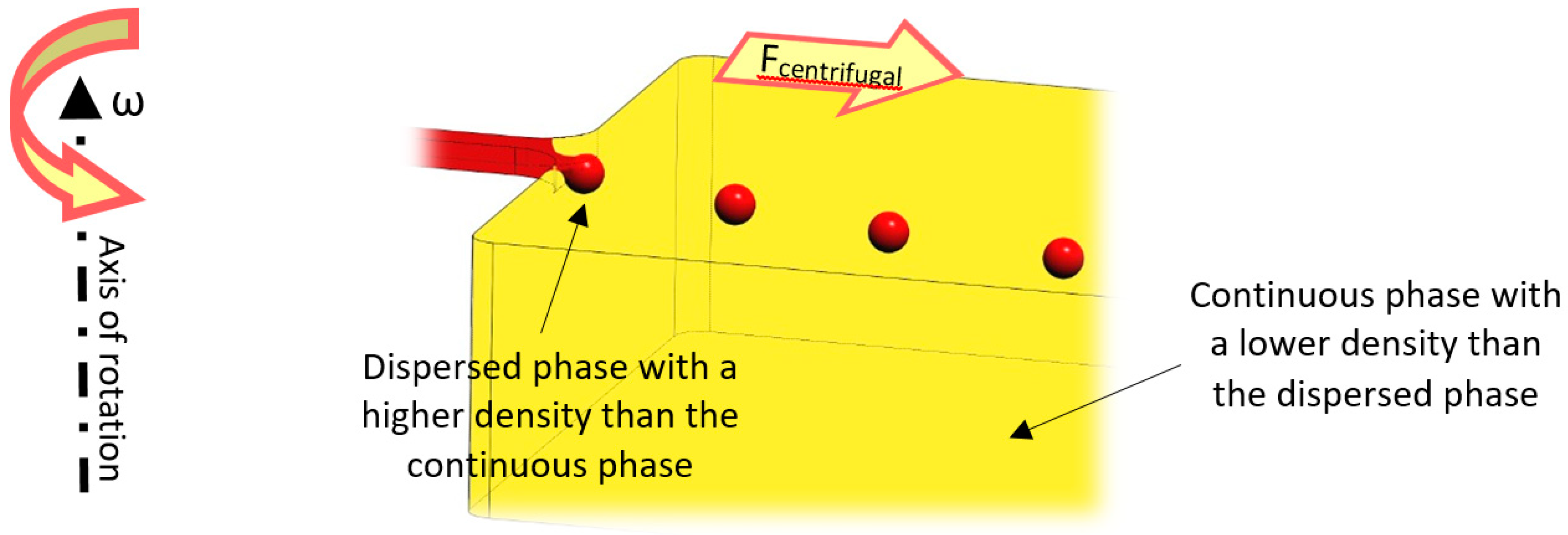
5. Theory
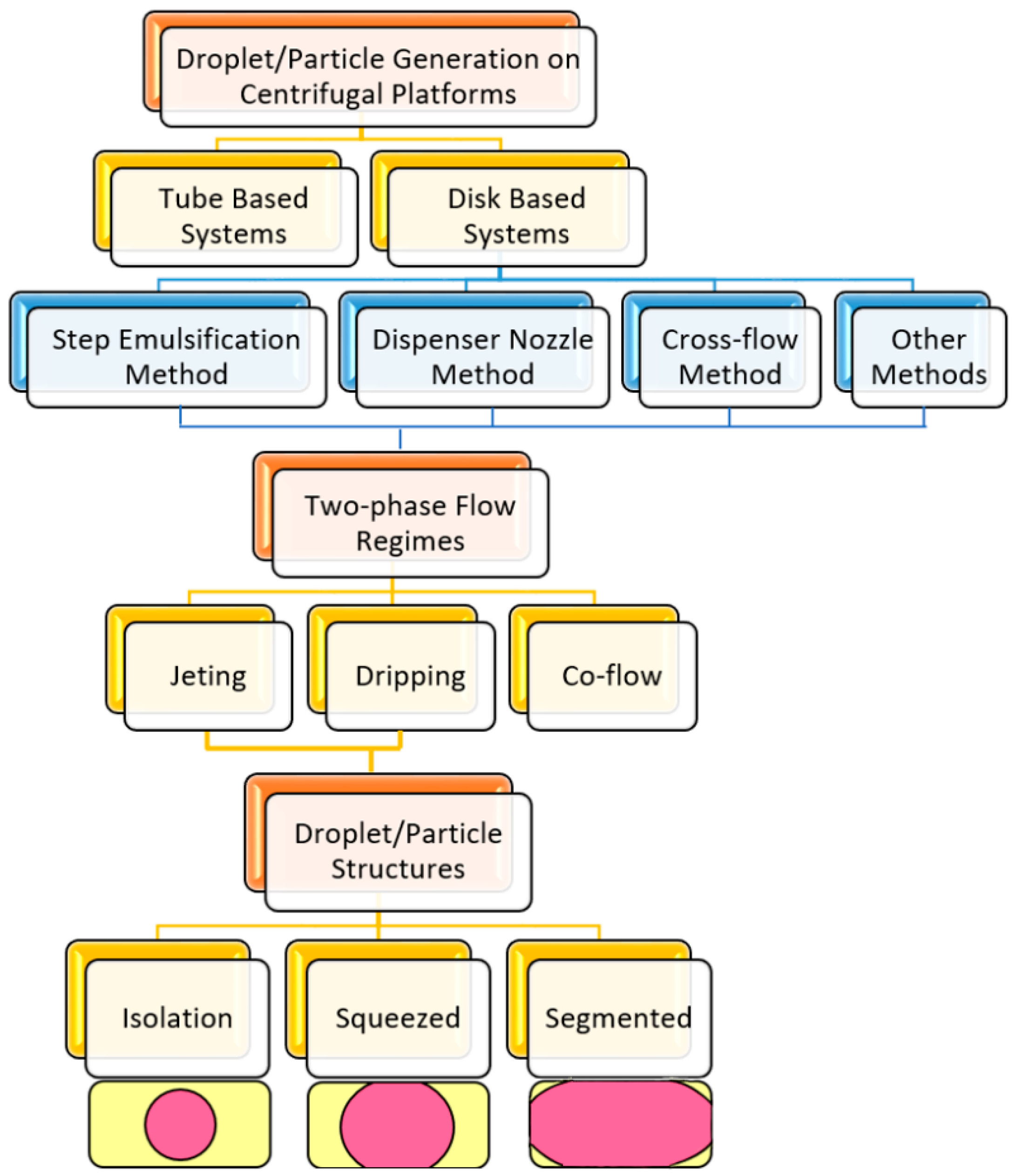
6. Different Methods of Droplet/Particle Generation on Centrifugal Platforms
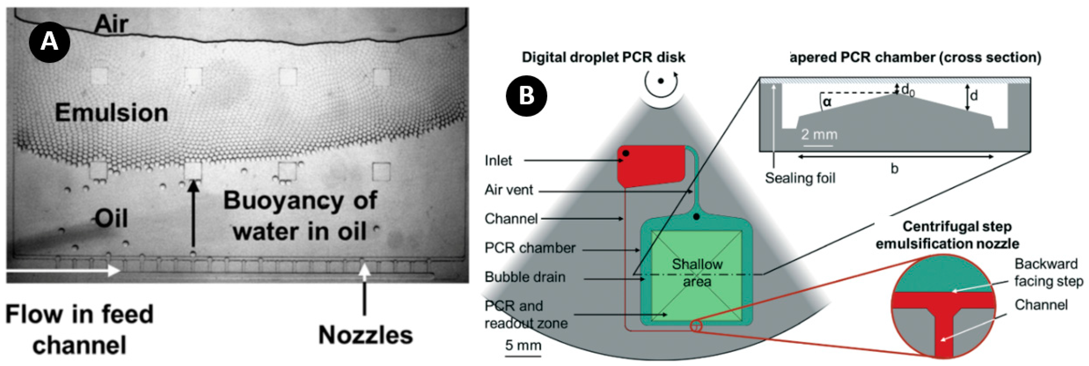
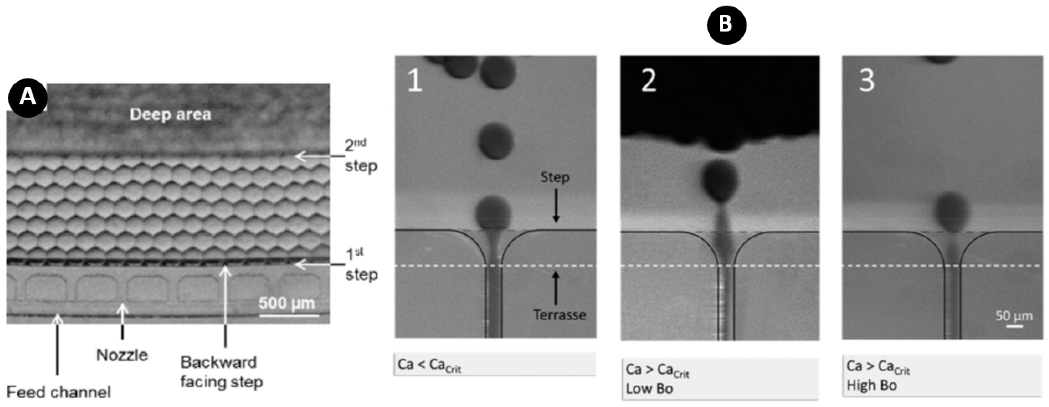
6.1. Step Emulsification Method
6.2. Dispenser Nozzle Method
6.3. Crossflow Method
6.4. Other Methods
7. Comparison of Different Centrifugal Methods
7.1. Step Emulsification
7.2. Dispenser Nozzle
7.3. Crossflow
7.4. Other Methods
8. Commercialization
9. Conclusions and Outlook
Author Contributions
Funding
Acknowledgments
Conflicts of Interest
References
- Tabeling, P. Introduction. In Introduction to Microfluidics, 1st ed.; Chen, S., Ed.; Oxford University Press: Paris, France, 2005; pp. 1–21. [Google Scholar]
- Manz, A.; Graber, N.; Widmer, H. Miniaturized total chemical analysis systems: A novel concept for chemical sensing. Sens. Actuators B Chem. 1990, 1, 244–248. [Google Scholar] [CrossRef]
- Verpoorte, E.; De Rooij, N. Microfluidics meets MEMS. Proc. IEEE 2003, 91, 930–953. [Google Scholar] [CrossRef] [Green Version]
- Nge, P.N.; Rogers, C.I.; Woolley, A.T. Advances in Microfluidic Materials, Functions, Integration, and Applications. Chem. Rev. 2013, 113, 2550–2583. [Google Scholar] [CrossRef] [PubMed] [Green Version]
- Whitesides, G.M. The origins and the future of microfluidics. Nature 2006, 442, 368–373. [Google Scholar] [CrossRef]
- Darhuber, A.A.; Troian, S.M. Principles of Microfluidic Actuation by Modulation of Surface Stresses. Annu. Rev. Fluid Mech. 2005, 37, 425–455. [Google Scholar] [CrossRef] [Green Version]
- Atencia, J.; Beebe, D.J. Controlled microfluidic interfaces. Nature 2004, 437, 648–655. [Google Scholar] [CrossRef]
- Cheng, Y.; Zheng, F.; Lu, J.; Shang, L.; Xie, Z.; Zhao, Y.; Chen, Y.; Gu, Z. Bioinspired Multicompartmental Microfibers from Microfluidics. Adv. Mater. 2014, 26, 5184–5190. [Google Scholar] [CrossRef]
- El-Ali, J.; Sorger, P.K.; Jensen, K.F. Cells on chips. Nature 2006, 442, 403–411. [Google Scholar] [CrossRef]
- Craighead, H. Future lab-on-a-chip technologies for interrogating individual molecules. Nature 2006, 442, 387–393. [Google Scholar] [CrossRef]
- Yager, P.; Edwards, T.; Fu, E.; Helton, K.; Nelson, K.; Tam, M.R.; Weigl, B.H. Microfluidic diagnostic technologies for global public health. Nature 2006, 442, 412–418. [Google Scholar] [CrossRef]
- Psaltis, D.; Quake, S.R.; Yang, C. Developing optofluidic technology through the fusion of microfluidics and optics. Nature 2006, 442, 381–386. [Google Scholar] [CrossRef] [PubMed]
- Demello, A.J. Control and detection of chemical reactions in microfluidic systems. Nature 2006, 442, 394–402. [Google Scholar] [CrossRef] [PubMed]
- Janasek, D.; Franzke, J.; Manz, A. Scaling and the design of miniaturized chemical-analysis systems. Nature 2006, 442, 374–380. [Google Scholar] [CrossRef]
- Beebe, D.J.; Mensing, G.A.; Walker, G.M. Physics and Applications of Microfluidics in Biology. Annu. Rev. Biomed. Eng. 2002, 4, 261–286. [Google Scholar] [CrossRef] [PubMed]
- Sun, Y.; Cai, B.; Wei, X.; Wang, Z.; Rao, L.; Meng, Q.-F.; Liao, Q.; Liu, W.; Guo, S.; Zhao, X. A valve-based microfluidic device for on-chip single cell treatments. Electrophoresis 2018, 40, 961–968. [Google Scholar] [CrossRef] [PubMed]
- Spotts, I.; Ismail, D.; Jaffar, N.; Collier, C.M. Fibre-optic sensing in digital microfluidic devices. Sens. Actuators A Phys. 2018, 280, 164–169. [Google Scholar] [CrossRef]
- Huang, Y.; Arriaga, L.; Weitz, D. Microfluidic Fabrication of Asymmetric Lipid Vesicles. APS 2019, 2019, Y63-008. [Google Scholar]
- Wu, B.; von der Ecken, S.; Swyer, I.; Li, C.; Jenne, A.; Vincent, F.; Schmidig, D.; Kuehn, T.; Beck, A.; Busse, F.; et al. Rapid Chemical Reaction Monitoring by Digital Microfluidics-NMR: Proof of Principle towards an Automated Synthetic Discovery Platform. Angew. Chem. Int. Ed. 2019, 58, 15372–15376. [Google Scholar] [CrossRef]
- Dixon, C.; Lamanna, J.; Wheeler, A.R. Direct loading of blood for plasma separation and diagnostic assays on a digital microfluidic device. Lab Chip 2020, 20, 1845–1855. [Google Scholar] [CrossRef]
- Tay, A.K.P.; Khoo, B.L.; Warkiani, M.E. Microfluidics for Fast and Frugal Diagnosis of Malaria, Sepsis, and HIV/AIDS. In Frugal Innovation in Bioengineering for the Detection of Infectious Diseases; Springer Science and Business Media LLC: Berlin/Heidelberg, Germany, 2018; pp. 57–75. [Google Scholar]
- Laser, D.J.; Santiago, J.G. A review of micropumps. J. Micromech. Microeng. 2004, 14, R35–R64. [Google Scholar] [CrossRef]
- Van Lintel, H.; Van De Pol, F.; Bouwstra, S. A piezoelectric micropump based on micromachining of silicon. Sens. Actuators 1988, 15, 153–167. [Google Scholar] [CrossRef] [Green Version]
- Döpper, J.; Clemens, M.; Ehrfeld, W.; Jung, S.; Kämper, K.-P.; Lehr, H. Micro gear pumps for dosing of viscous fluids. J. Micromech. Microeng. 1997, 7, 230–232. [Google Scholar] [CrossRef]
- Evans, J.; Liepmann, D.; Pisano, A.P. Planar laminar mixer. Proc. IEEE Micro Electro Mech. Syst. 1997, 10, 96–101. [Google Scholar]
- Carter, M. Selling: Outside the box. Text. Rent. 2006, 89, 50. [Google Scholar]
- Mohith, S.; Karanth, P.N.; Kulkarni, S. Recent trends in mechanical micropumps and their applications: A review. Mechatronics 2019, 60, 34–55. [Google Scholar] [CrossRef]
- Wang, G.; Tan, J.; Tang, M.; Zhang, C.; Zhang, N.; Ji, W.; Chen, J.; Ho, H.-P.; Zhang, X. Binary centrifugal microfluidics enabling novel, digital addressable functions for valving and routing. Lab Chip 2018, 18, 1197–1206. [Google Scholar] [CrossRef]
- Cozzens, M.A. Droplet Generation on a Centrifugal Disc: Novel Applications and Numerical Characterization Studies. Master’s Thesis, University of California, Oakland, CA, USA, 2011. [Google Scholar]
- Verlinden, E.; Madadelahi, M.; Sarajlic, E.; Shamloo, A.; Engel, A.; Staufer, U.; Ghatkesar, M.K. Volume and concentration dosing in picolitres using a two-channel microfluidic AFM cantilever. Nanoscale 2020, 12, 10292–10305. [Google Scholar] [CrossRef]
- Schüler, F.; Schwemmer, F.; Trotter, M.; Wadle, S.; Zengerle, R.; Von Stetten, F.; Paust, N. Centrifugal step emulsification applied for absolute quantification of nucleic acids by digital droplet RPA. Lab Chip 2015, 15, 2759–2766. [Google Scholar] [CrossRef] [Green Version]
- Lake, J.R.; Heyde, K.C.; Ruder, W.C. Low-cost feedback-controlled syringe pressure pumps for microfluidics applications. PLoS ONE 2017, 12, e0175089. [Google Scholar] [CrossRef]
- Lin, F.; Saadi, W.; Rhee, S.W.; Wang, S.-J.; Mittal, S.; Jeon, N.L. Generation of dynamic temporal and spatial concentration gradients using microfluidic devices. Lab Chip 2004, 4, 164. [Google Scholar] [CrossRef] [Green Version]
- Walker, G.M.; Beebe, D.J. A passive pumping method for microfluidic devices. Lab Chip 2002, 2, 131–134. [Google Scholar] [CrossRef] [PubMed]
- Madadelahi, M.; Shamloo, A. Newtonian and generalized Newtonian reacting flows in serpentine microchannels: Pressure driven and centrifugal microfluidics. J. Non-Newton. Fluid Mech. 2018, 251, 88–96. [Google Scholar] [CrossRef]
- Shamloo, A.; Selahi, A.; Madadelahi, M. Designing and modeling a centrifugal microfluidic device to separate target blood cells. J. Micromech. Microeng. 2016, 26, 035017. [Google Scholar] [CrossRef]
- Shamloo, A.; Madadelahi, M.; Abdorahimzadeh, S. Three-dimensional numerical simulation of a novel electroosmotic micromixer. Chem. Eng. Process. Process Intensif. 2017, 119, 25–33. [Google Scholar] [CrossRef]
- Podlinski, J.; Danowska, M.; Izdebski, T.; Dors, M. Electrohydrodynamic Pump Supplied by Unipolar Direct Current Voltage With Both Positive and Negative Corona Discharge. J. Fluids Eng. 2018, 141, 011206. [Google Scholar] [CrossRef]
- Elmaboud, Y.A.; I Abdelsalam, S. DC/AC magnetohydrodynamic-micropump of a generalized Burger’s fluid in an annulus. Phys. Scr. 2019, 94, 115209. [Google Scholar] [CrossRef]
- Azimi-Boulali, J.; Zakeri, M.; Shoaran, M. A study on the 3D fluid flow of MHD micropump. J. Braz. Soc. Mech. Sci. Eng. 2019, 41, 478. [Google Scholar] [CrossRef]
- Azimi-Boulali, J.; Zakeri, M.; Javidfard, M. A numerical study on characteristics of the magnetohydrodynamic micropumps. In Proceedings of the 2015 3rd RSI International Conference on Robotics and Mechatronics (ICROM), Tehran, Iran, 7–9 October 2015; pp. 401–405. [Google Scholar]
- Haeberle, S.; Naegele, L.; Burger, R.; Von Stetten, F.; Zengerle, R.; Ducrée, J. Alginate bead fabrication and encapsulation of living cells under centrifugally induced artificial gravity conditions. J. Microencapsul. 2008, 25, 267–274. [Google Scholar] [CrossRef]
- Soroori, S.; Rodríguez-Delgado, J.M.; Kido, H.; Dieck-Assad, G.; Madou, M.J.; Kulinsky, L. The use of polybutene for controlling the flow of liquids in centrifugal microfluidic systems. Microfluid. Nanofluidics 2016, 20, 1–13. [Google Scholar] [CrossRef]
- Lim, S.; Choi, B. A study on the MHD (magnetohydrodynamic) micropump with side-walled electrodes. J. Mech. Sci. Technol. 2009, 23, 739–749. [Google Scholar] [CrossRef]
- Wang, J.M.; Yang, L.J. Electro-Hydro-Dynamic (EHD) micropumps with electrode protection by parylene and gelatin. Tamkang J. Sci. Eng. 2005, 8, 231–236. [Google Scholar]
- Haeberle, S.; Zengerle, R.; Ducrée, J. Centrifugal generation and manipulation of droplet emulsions. Microfluid. Nanofluidics 2007, 3, 65–75. [Google Scholar] [CrossRef]
- Schulz, M.; Von Stetten, F.; Zengerle, R.; Paust, N. Centrifugal Step Emulsification: How Buoyancy Enables High Generation Rates of Monodisperse Droplets. Langmuir 2019, 35, 9809–9815. [Google Scholar] [CrossRef] [PubMed]
- Teh, S.-Y.; Lin, R.; Hung, L.-H.; Lee, A.P. Droplet microfluidics. Lab Chip 2008, 8, 198. [Google Scholar] [CrossRef] [PubMed]
- Liu, H.; Zhang, Y. Droplet formation in a T-shaped microfluidic junction. J. Appl. Phys. 2009, 106, 34906. [Google Scholar] [CrossRef] [Green Version]
- Madadelahi, M.; Shamloo, A. Droplet-based flows in serpentine microchannels: Chemical reactions and secondary flows. Int. J. Multiph. Flow 2017, 97, 186–196. [Google Scholar] [CrossRef]
- Madadelahi, M.; Ghazimirsaeed, E.; Shamloo, A. Design and fabrication of a two-phase diamond nanoparticle aided fast PCR device. Anal. Chim. Acta 2019, 1068, 28–40. [Google Scholar] [CrossRef]
- Tjhung, K.F.; Burnham, S.; Anany, H.; Griffiths, M.W.; Derda, R. Rapid Enumeration of Phage in Monodisperse Emulsions. Anal. Chem. 2014, 86, 5642–5648. [Google Scholar] [CrossRef]
- Xu, Q.; Hashimoto, M.; Dang, T.; Hoare, T.; Kohane, D.S.; Whitesides, G.M.; Langer, R.; Anderson, D.G. Preparation of Monodisperse Biodegradable Polymer Microparticles Using a Microfluidic Flow-Focusing Device for Controlled Drug Delivery. Small 2009, 5, 1575–1581. [Google Scholar] [CrossRef] [Green Version]
- Ogończyk, D.; Siek, M.; Garstecki, P. Microfluidic formulation of pectin microbeads for encapsulation and controlled release of nanoparticles. Biomicrofluidics 2011, 5, 13405. [Google Scholar] [CrossRef] [Green Version]
- Hugo, S.; Land, K.J.; Madou, M.J.; Kido, H. A centrifugal microfluidic platform for point-of-care diagnostic applications. S. Afr. J. Sci. 2014, 110, 42–48. [Google Scholar] [CrossRef] [Green Version]
- Huebner, A.; Srisa-Art, M.; Holt, D.; Abell, C.; Hollfelder, F.; Demello, A.J.; Edel, J.B. Quantitative detection of protein expression in single cells using droplet microfluidics. Chem. Commun. 2007, 1218–1220. [Google Scholar] [CrossRef] [PubMed]
- Guo, M.T.; Rotem, A.; Heyman, J.A.; Weitz, D.A. Droplet microfluidics for high-throughput biological assays. Lab Chip 2012, 12, 2146–2155. [Google Scholar] [CrossRef] [PubMed]
- Brouzes, E.; Medkova, M.; Savenelli, N.; Marran, D.; Twardowski, M.; Hutchison, J.B.; Rothberg, J.M.; Link, D.R.; Perrimon, N.; Samuels, M.L. Droplet microfluidic technology for single-cell high-throughput screening. Proc. Natl. Acad. Sci. USA 2009, 106, 14195–14200. [Google Scholar] [CrossRef] [Green Version]
- Kintses, B.; Hein, C.; Mohamed, M.F.; Fischlechner, M.; Courtois, F.; Lainé, C.; Hollfelder, F. Picoliter Cell Lysate Assays in Microfluidic Droplet Compartments for Directed Enzyme Evolution. Chem. Boil. 2012, 19, 1001–1009. [Google Scholar] [CrossRef] [Green Version]
- Agresti, J.J.; Antipov, E.; Abate, A.R.; Ahn, K.; Rowat, A.C.; Baret, J.-C.; Marquez, M.; Klibanov, A.M.; Griffiths, A.D.; Weitz, D.A. Ultrahigh-throughput screening in drop-based microfluidics for directed evolution. Proc. Natl. Acad. Sci. USA 2010, 107, 4004–4009. [Google Scholar] [CrossRef] [PubMed] [Green Version]
- Li, Z.; Liu, Y.; Wei, Q.; Liu, Y.; Liu, W.; Zhang, X.; Yu, Y. Picoliter Well Array Chip-Based Digital Recombinase Polymerase Amplification for Absolute Quantification of Nucleic Acids. PLoS ONE 2016, 11, e0153359. [Google Scholar] [CrossRef]
- Ahmed, N.; Sukovich, D.; Abate, A.R. Operation of Droplet-Microfluidic Devices with a Lab Centrifuge. Micromachines 2016, 7, 161. [Google Scholar] [CrossRef] [Green Version]
- Kar, S.; Joshi, S.; Chaudhury, K.; Maiti, T.K.; Chakraborty, S. Generation of droplets to serpentine threads on a rotating compact-disk platform. Appl. Phys. Lett. 2015, 107, 244101. [Google Scholar] [CrossRef]
- Chen, Z.; Liao, P.; Zhang, F.; Jiang, M.; Zhu, Y.; Huang, Y. Centrifugal micro-channel array droplet generation for highly parallel digital PCR. Lab Chip 2017, 17, 235–240. [Google Scholar] [CrossRef]
- Hindson, B.J.; Ness, K.D.; Masquelier, D.A.; Belgrader, P.; Heredia, N.J.; Makarewicz, A.J.; Bright, I.J.; Lucero, M.Y.; Hiddessen, A.L.; Legler, T.C.; et al. High-throughput droplet digital PCR system for absolute quantitation of DNA copy number. Anal. Chem. 2011, 83, 8604–8610. [Google Scholar] [CrossRef] [PubMed]
- Mazutis, L.; Araghi, A.F.; Miller, O.J.; Baret, J.-C.; Frenz, L.; Jànoshàzi, À.; Taly, V.; Miller, B.F.; Hutchison, J.B.; Link, D.; et al. Droplet-Based Microfluidic Systems for High-Throughput Single DNA Molecule Isothermal Amplification and Analysis. Anal. Chem. 2009, 81, 4813–4821. [Google Scholar] [CrossRef] [PubMed]
- Beneyton, T.; Thomas, S.; Griffiths, A.D.; Nicaud, J.-M.; Drevelle, A.; Rossignol, T. Droplet-based microfluidic high-throughput screening of heterologous enzymes secreted by the yeast Yarrowia lipolytica. Microb. Cell Factories 2017, 16, 18. [Google Scholar] [CrossRef] [PubMed] [Green Version]
- Mazutis, L.; Gilbert, J.; Ung, W.; A Weitz, D.; Griffiths, A.D.; A Heyman, J. Single-cell analysis and sorting using droplet-based microfluidics. Nat. Protoc. 2013, 8, 870–891. [Google Scholar] [CrossRef] [PubMed]
- Eral, H.B.; Safai, E.R.; Keshavarz, B.; Kim, J.J.; Lee, J.; Doyle, P.S.; Lee, J. Governing Principles of Alginate Microparticle Synthesis with Centrifugal Forces. Langmuir 2016, 32, 7198–7209. [Google Scholar] [CrossRef] [PubMed]
- Sultana, K.; Godward, G.; Reynolds, N.; Arumugaswamy, R.; Peiris, P.; Kailasapathy, K. Encapsulation of probiotic bacteria with alginate–starch and evaluation of survival in simulated gastrointestinal conditions and in yoghurt. Int. J. Food Microbiol. 2000, 62, 47–55. [Google Scholar] [CrossRef]
- Matricardi, P.; Di Meo, C.; Coviello, T.; Alhaique, F. Recent advances and perspectives on coated alginate microspheres for modified drug delivery. Expert Opin. Drug Deliv. 2008, 5, 417–425. [Google Scholar] [CrossRef]
- George, M.; Abraham, T.E. Polyionic hydrocolloids for the intestinal delivery of protein drugs: Alginate and chitosan—A review. J. Control. Release 2006, 114, 1–14. [Google Scholar] [CrossRef]
- Shin, D.-C.; Morimoto, Y.; Sawayama, J.; Miura, S.; Takeuchi, S. Centrifuge-based step emulsification device for simple and fast generation of monodisperse picoliter droplets. Sens. Actuators B Chem. 2019, 301, 127164. [Google Scholar] [CrossRef]
- Nisisako, T.; Torii, T.; Takahashi, T.; Takizawa, Y. Synthesis of Monodisperse Bicolored Janus Particles with Electrical Anisotropy Using a Microfluidic Co-Flow System. Adv. Mater. 2006, 18, 1152–1156. [Google Scholar] [CrossRef]
- Behrend, C.J.; Anker, J.; McNaughton, B.H.; Brasuel, M.; Philbert, M.A.; Kopelman, R. Metal-Capped Brownian and Magnetically Modulated Optical Nanoprobes (MOONs): Micromechanics in Chemical and Biological Microenvironments†. J. Phys. Chem. B 2004, 108, 10408–10414. [Google Scholar] [CrossRef]
- Howse, J.R.; Jones, R.A.L.; Ryan, A.; Gough, T.; Vafabakhsh, R.; Golestanian, R. Self-motile colloidal particles: From directed propulsion to random walk. Phys. Rev. Lett. 2007, 99, 048102. [Google Scholar] [CrossRef] [Green Version]
- Golestanian, R.; Liverpool, T.B.; Ajdari, A. Propulsion of a molecular machine by asymmetric distribution of reaction products. Phys. Rev. Lett. 2005, 94, 220801. [Google Scholar] [CrossRef] [PubMed] [Green Version]
- Hou, Y.; Li, Y.; Wang, L.; Chen, D.; Bao, M.; Wang, Z. Amphiphilic Janus particles for efficient dispersion of oil contaminants in seawater. J. Colloid Interface Sci. 2019, 556, 54–64. [Google Scholar] [CrossRef]
- Liu, M.; Sun, X.-T.; Yang, C.-G.; Xu, Z.-R. On-chip preparation of calcium alginate particles based on droplet templates formed by using a centrifugal microfluidic technique. J. Colloid Interface Sci. 2016, 466, 20–27. [Google Scholar] [CrossRef] [PubMed]
- Ferrara, K.W.; Pollard, R.; Borden, M. Ultrasound Microbubble Contrast Agents: Fundamentals and Application to Gene and Drug Delivery. Annu. Rev. Biomed. Eng. 2007, 9, 415–447. [Google Scholar] [CrossRef] [PubMed] [Green Version]
- Prentice, P.; Cuschieri, A.; Dholakia, K.; Prausnitz, M.; Campbell, P.A. Membrane disruption by optically controlled microbubble cavitation. Nat. Phys. 2005, 1, 107–110. [Google Scholar] [CrossRef] [Green Version]
- Stone, H.; Stroock, A.; Ajdari, A. Engineering Flows IN Small Devices. Annu. Rev. Fluid Mech. 2004, 36, 381–411. [Google Scholar] [CrossRef] [Green Version]
- Oliveira, C.; Rodrigues, R.; Rubio, J. A new technique for characterizing aerated flocs in a flocculation–microbubble flotation system. Int. J. Miner. Process. 2010, 96, 36–44. [Google Scholar] [CrossRef]
- Lindner, J.R. Microbubbles in medical imaging: Current applications and future directions. Nat. Rev. Drug Discov. 2004, 3, 527–533. [Google Scholar] [CrossRef]
- Song, H.; Chen, D.L.; Ismagilov, R.F. Reactions in Droplets in Microfluidic Channels. Angew. Chem.—Int. Ed. 2007, 38, 7336–7356. [Google Scholar] [CrossRef] [Green Version]
- Prakash, M.; Gershenfeld, N.; Klein, C.; Ren, P.-G.; Kass, S.; Donck, L.V.; Moechars, D.; Hsueh, A.J.; Zhang, J. Microfluidic Bubble Logic. Science 2007, 315, 832–835. [Google Scholar] [CrossRef] [PubMed] [Green Version]
- Madadelahi, M.; Shamloo, A.; Salehi, S.S. Numerical Simulation of Bio-Chemical Diffusion in Bone Scaffolds. World Acad. Sci. Eng. Technol. 2017, 11, 211–214. [Google Scholar]
- Smith, S.; Mager, D.; Perebikovsky, A.; Shamloo, E.; Kinahan, D.; Mishra, R.; Delgado, S.M.T.; Kido, H.; Saha, S.; Ducrée, J.; et al. CD-Based Microfluidics for Primary Care in Extreme Point-of-Care Settings. Micromachines 2016, 7, 22. [Google Scholar] [CrossRef] [PubMed] [Green Version]
- Zhu, P.; Wang, L. Passive and active droplet generation with microfluidics: A review. Lab Chip 2017, 17, 34–75. [Google Scholar] [CrossRef]
- Link, D.R.; Grasland-Mongrain, E.; Duri, A.; Sarrazin, F.; Cheng, Z.; Cristobal, G.; Marquez, M.; Weitz, D.A. Electric control of droplets in microfluidic devices. Angew. Chem.—Int. Ed. 2006, 45, 2556–2560. [Google Scholar] [CrossRef]
- Tan, S.H.; Semin, B.; Baret, J.-C. Microfluidic flow-focusing in ac electric fields. Lab Chip 2014, 14, 1099–1106. [Google Scholar] [CrossRef] [Green Version]
- Li, Y.; Jain, M.; Ma, Y.; Nandakumar, K. Control of the breakup process of viscous droplets by an external electric field inside a microfluidic device. Soft Matter 2015, 11, 3884–3899. [Google Scholar] [CrossRef]
- He, M.; Kuo, J.S.; Chiu, D.T. Electro-generation of single femtoliter- and picoliter-volume aqueous droplets in microfluidic systems. Appl. Phys. Lett. 2005, 87, 031916. [Google Scholar] [CrossRef]
- He, M.; Kuo, J.S.; Chiu, D.T. Effects of Ultrasmall Orifices on the Electrogeneration of Femtoliter-Volume Aqueous Droplets. Langmuir 2006, 22, 6408–6413. [Google Scholar] [CrossRef] [Green Version]
- He, P.; Kim, H.; Luo, D.; Marquez, M.; Cheng, Z. Low-frequency ac electro-flow-focusing microfluidic emulsification. Appl. Phys. Lett. 2010, 96, 174103. [Google Scholar] [CrossRef]
- Kahkeshani, S.; Di Carlo, D. Drop formation using ferrofluids driven magnetically in a step emulsification device. Lab Chip 2016, 16, 2474–2480. [Google Scholar] [CrossRef] [PubMed]
- Li, H.; Wu, Y.; Wang, X.; Zhu, C.; Fu, T.; Ma, Y. Magnetofluidic control of the breakup of ferrofluid droplets in a microfluidic Y-junction. RSC Adv. 2016, 6, 778–785. [Google Scholar] [CrossRef]
- Wu, Y.; Fu, T.; Ma, Y.; Li, H.Z. Ferrofluid droplet formation and breakup dynamics in a microfluidic flow-focusing device. Soft Matter 2013, 9, 9792–9798. [Google Scholar] [CrossRef]
- Liu, J.; Yap, Y.F.; Nguyen, A.V. Numerical study of the formation process of ferrofluid droplets. Phys. Fluids 2011, 23, 72008. [Google Scholar] [CrossRef] [Green Version]
- Tan, S.H.; Nguyen, A.V. Generation and manipulation of monodispersed ferrofluid emulsions: The effect of a uniform magnetic field in flow-focusing and T-junction configurations. Phys. Rev. E 2011, 84. [Google Scholar] [CrossRef] [Green Version]
- Haeberle, S.; Brenner, T.; Schlosser, H.-P.; Zengerle, R.; Ducrée, J. Centrifugal Micromixery. Chem. Eng. Technol. 2005, 28, 613–616. [Google Scholar] [CrossRef]
- Haeberle, S.; Zengerle, R. Microfluidic platforms for lab-on-a-chip applications. Lab Chip 2007, 7, 1094–1110. [Google Scholar] [CrossRef]
- Madadelahi, M.; Acosta-Soto, L.F.; Hosseini, S.; Martinez-Chapa, S.O.; Madou, M.J. Mathematical modeling and computational analysis of centrifugal microfluidic platforms: A review. Lab Chip 2020. [Google Scholar] [CrossRef]
- Ren, Y.; Leung, W.W.-F. Numerical Investigation of Cell Encapsulation for Multiplexing Diagnostic Assays Using Novel Centrifugal Microfluidic Emulsification and Separation Platform. Micromachines 2016, 7, 17. [Google Scholar] [CrossRef] [Green Version]
- Sugiura, S.; Nakajima, M.; Kumazawa, N.; Iwamoto, S.; Seki, M. Characterization of Spontaneous Transformation-Based Droplet Formation during Microchannel Emulsification. J. Phys. Chem. B 2002, 106, 9405–9409. [Google Scholar] [CrossRef]
- Nunes, J.K.; Tsai, S.S.H.; Wan, J.; Stone, H.A. Dripping and jetting in microfluidic multiphase flows applied to particle and fibre synthesis. J. Phys. D Appl. Phys. 2013, 46, 114002. [Google Scholar] [CrossRef] [PubMed]
- Dendukuri, D.; Tsoi, K.; Hatton, T.A.; Doyle, P.S. Controlled Synthesis of Nonspherical Microparticles Using Microfluidics. Langmuir 2005, 21, 2113–2116. [Google Scholar] [CrossRef] [PubMed]
- Shestopalov, I.; Tice, J.D.; Ismagilov, R.F. Multi-step synthesis of nanoparticles performed on millisecond time scale in a microfluidic droplet-based system. Lab Chip 2004, 4, 316–321. [Google Scholar] [CrossRef] [PubMed] [Green Version]
- Schuler, F.; Paust, N.; Zengerle, R.; von Stetten, F. Centrifugal step emulsification can producewater in oil emulsions with extremely high internal volume fractions. Micromachines 2015, 6, 1180–1188. [Google Scholar] [CrossRef] [Green Version]
- Ouyang, L.; Yao, R.; Zhao, Y.; Sun, W. Effect of bioink properties on printability and cell viability for 3D bioplotting of embryonic stem cells. Biofabrication 2016, 8, 035020. [Google Scholar] [CrossRef]
- Schuler, F.; Trotter, M.; Geltman, M.; Schwemmer, F.; Wadle, S.; Garrido, E.D.; Lopez, M.; Cervera-Acedo, C.; Santibáñez, P.; Von Stetten, F.; et al. Digital droplet PCR on disk. Lab Chip 2016, 16, 208–216. [Google Scholar] [CrossRef] [Green Version]
- Amstad, E.; Chemama, M.; Eggersdorfer, M.; Arriaga, L.R.; Brenner, M.P.; Weitz, D.A. Robust scalable high throughput production of monodisperse drops. Lab Chip 2016, 16, 4163–4172. [Google Scholar] [CrossRef]
- Ganesh, S.V. Integration of Stable Droplet Formation on a CD Microfluidic Device for Extreme Point of Care Applications. Master's Thesis, University of California Irvine, Irvine, CA, USA, 2017. [Google Scholar]
- Tan, W.-H.; Takeuchi, S. Arrayed Monodisperse Micro-Alginate Beads in μ-Fluidic Traps for Cell Assay. In Proceedings of the 19th IEEE International Conference on Micro Electro Mechanical Systems, Istanbul, Turkey, 22–26 January 2006; pp. 534–537. [Google Scholar]
- Mark, D.; Haeberle, S.; Zengerle, R.; Ducrée, J.; Vladisavljević, G.T. Manufacture of chitosan microbeads using centrifugally driven flow of gel-forming solutions through a polymeric micronozzle. J. Colloid Interface Sci. 2009, 336, 634–641. [Google Scholar] [CrossRef] [Green Version]
- Hwang, J.K.; Shin, H.H. Rheological properties of chitosan solutions. Korea-Aust. Rheol. J. 2000, 12, 175–179. [Google Scholar]
- Taylor, G.I. The formation of emulsions in definable fields of flow. Proc. R. Soc. Ser. A Math. Phys. Sci. 1934, 146, 501–523. [Google Scholar] [CrossRef] [Green Version]
- Stone, H.A. Dynamics of Drop Deformation and Breakup in Viscous Fluids. Annu. Rev. Fluid Mech. 1994, 26, 65–102. [Google Scholar] [CrossRef]
- Maeda, K.; Onoe, H.; Takinoue, M.; Takeuchi, S. Controlled Synthesis of 3D Multi-Compartmental Particles with Centrifuge-Based Microdroplet Formation from a Multi-Barrelled Capillary. Adv. Mater. 2012, 24, 1340–1346. [Google Scholar] [CrossRef] [PubMed]
- Yildirim, O.E.; Xu, Q.; Basaran, O.A. Analysis of the drop weight method. Phys. Fluids 2005, 17, 062107. [Google Scholar] [CrossRef]
- Morimoto, Y.; Onuki, M.; Takeuchi, S. Mass Production of Cell-Laden Calcium Alginate Particles with Centrifugal Force. Adv. Healthc. Mater. 2017, 6, 1601375. [Google Scholar] [CrossRef] [PubMed]
- Matsunaga, Y.T.; Morimoto, Y.; Takeuchi, S. Molding Cell Beads for Rapid Construction of Macroscopic 3D Tissue Architecture. Adv. Mater. 2011, 23. [Google Scholar] [CrossRef] [PubMed]
- Song, H.; Bringer, M.R.; Tice, J.D.; Gerdts, C.J.; Ismagilov, R.F. Experimental test of scaling of mixing by chaotic advection in droplets moving through microfluidic channels. Appl. Phys. Lett. 2003, 83, 4664–4666. [Google Scholar] [CrossRef] [PubMed] [Green Version]
- Günther, A.; Jhunjhunwala, M.; Thalmann, M.; Schmidt, M.A.; Jensen, K.F. Micromixing of Miscible Liquids in Segmented Gas−Liquid Flow. Langmuir 2005, 21, 1547–1555. [Google Scholar] [CrossRef] [PubMed]
- Nisisako, T.; Torii, T.; Higuchi, T. Novel microreactors for functional polymer beads. Chem. Eng. J. 2004, 101, 23–29. [Google Scholar] [CrossRef]
- Nisisako, T.; Torii, T.; Higuchi, T. Controlled production of functional polymeric microspheres using multi-phase mi- crofluidics. In Proceedings of the lTAS 2004, 8th International Conference on Miniaturized Systems for Chemistry and Life Sciences, Malmö, Sweden, 26–30 September 2004; pp. 408–410. [Google Scholar]
- Chakraborty, D.; Chakraborty, S. Controlled microbubble generation on a compact disk. Appl. Phys. Lett. 2010, 97, 234103. [Google Scholar] [CrossRef]
- Tang, G.; Jin, J.; Chen, Q.; Di, S.; Du, R. Simulations of centrifugal microfluidic droplet formation using two-phase level set method. In Proceedings of the 2014 International Conference on Manipulation, Manufacturing and Measurement on the Nanoscale (3M-NANO), Taipei, Taiwan, 27–31 October 2014; pp. 155–159. [Google Scholar] [CrossRef]
- Singh, K.; Gupta, A.; Buchner, A.-J.; Ibis, F.; Pronk, J.W.; Tam, D.; Eral, H.B. Analysis of centrifugal homogenization and its applications for emulsification & mechanical cell lysis. J. Colloid Interface Sci. 2019, 547, 127–135. [Google Scholar] [CrossRef] [PubMed]
- Davies, J. A physical interpretation of drop sizes in homogenizers and agitated tanks, including the dispersion of viscous oils. Chem. Eng. Sci. 1987, 42, 1671–1676. [Google Scholar] [CrossRef]
- Madadelahi, M.; Madou, M.J.; Nokoorani, Y.D.; Shamloo, A.; Martinez-Chapa, S.O. Fluidic barriers in droplet-based centrifugal microfluidics: Generation of multiple emulsions and microspheres. Sens. Actuators B Chem. 2020, 311, 127833. [Google Scholar] [CrossRef]
- Strohmeier, O.; Keller, M.; Schwemmer, F.; Zehnle, S.; Mark, D.; Von Stetten, F.; Zengerle, R.; Paust, N. Centrifugal microfluidic platforms: Advanced unit operations and applications. Chem. Soc. Rev. 2015, 44, 6187–6229. [Google Scholar] [CrossRef] [Green Version]
- Available online: https://www.abaxis.com/medical/piccolo-xpress?language_content_entity=en (accessed on 1 June 2020).
- Available online: https://www.meridianbioscience.com/platform/molecular/revogene/ (accessed on 1 June 2020).
- Available online: https://news.tsinghua.edu.cn/publish/thunewsen/9671/2020/20200312110654875547982/20200312110654875547982_.html (accessed on 1 June 2020).
- Available online: http://www.pr.uni-freiburg.de/pm-en/online-magazine/invent-and-establish/proof-of-corona-in-35-minutes (accessed on 1 June 2020).


| Material | Diameter Range | Volume Fraction | CV | Production Rate | Rotating Acceleration/Frequency | Ref. | ||
|---|---|---|---|---|---|---|---|---|
| Dispersed Phase | Continuous Phase | Surfactant | ||||||
| - | Novec 7500 | Picosurf-1 2% w/v | 120~170 μm | 97.2% at 20 Hz | 2–4% | >500 Droplets per second per nozzle | 5~40 Hz | [31] |
| Water, inkjet printer ink in water (10% v/v) and low melting agarose (1.25% w/v). | Novec 7500 | Picosurf-1 2% w/v | 156 μm | 97.2~99% | 4% | 3700/s with 72 nozzles | 10~20 Hz | [109] |
| Water | Novec 7500 | Picosurf-1 5% | 100 μm | - | <5% | 2800/s per nozzle | 1~100 Hz | [47] |
| - | Silicone oil, Fluorinert, Bio-Rad | - | 103~200 μm | 6~14% | - | 8.3~41.7 Hz | [113] | |
| - | Fluorinated oil | - | 147 μm | 1.4% | 11,000 | 0.5~10 Hz | [111] | |
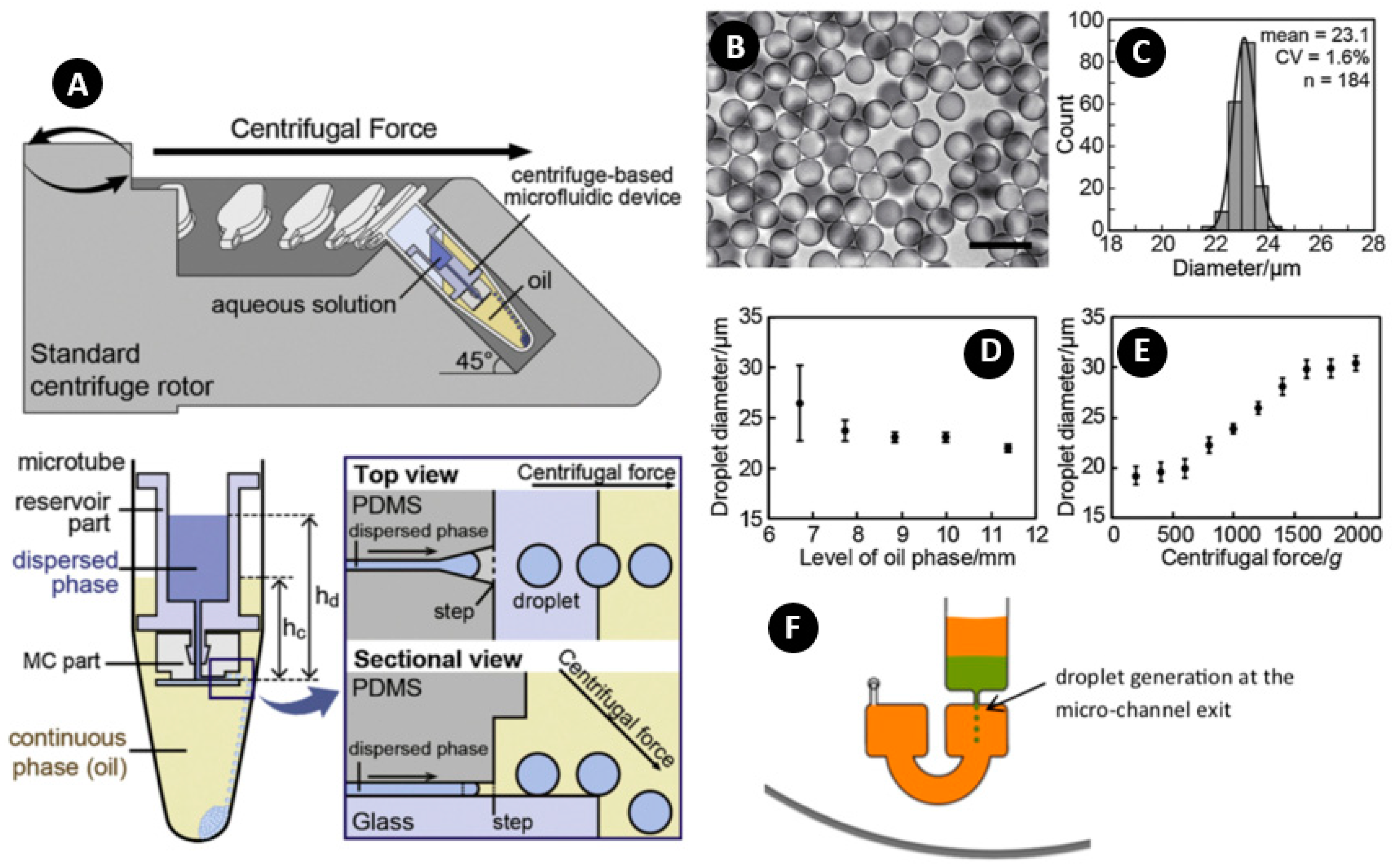
| Water | Mineral oil containing 2 wt% Span 80 | - | 18 to 90 μm, ave 23.1 μm | - | 1.6% | - | 150~1000 g | [73] |
| Material | Diameter Range (µm) | Nozzle Size (µm) | CV (%) | Production Rate | Rotating Acceleration/Frequency | Ref. | |
|---|---|---|---|---|---|---|---|
| Dispersed Phase | Continuous Phase | ||||||
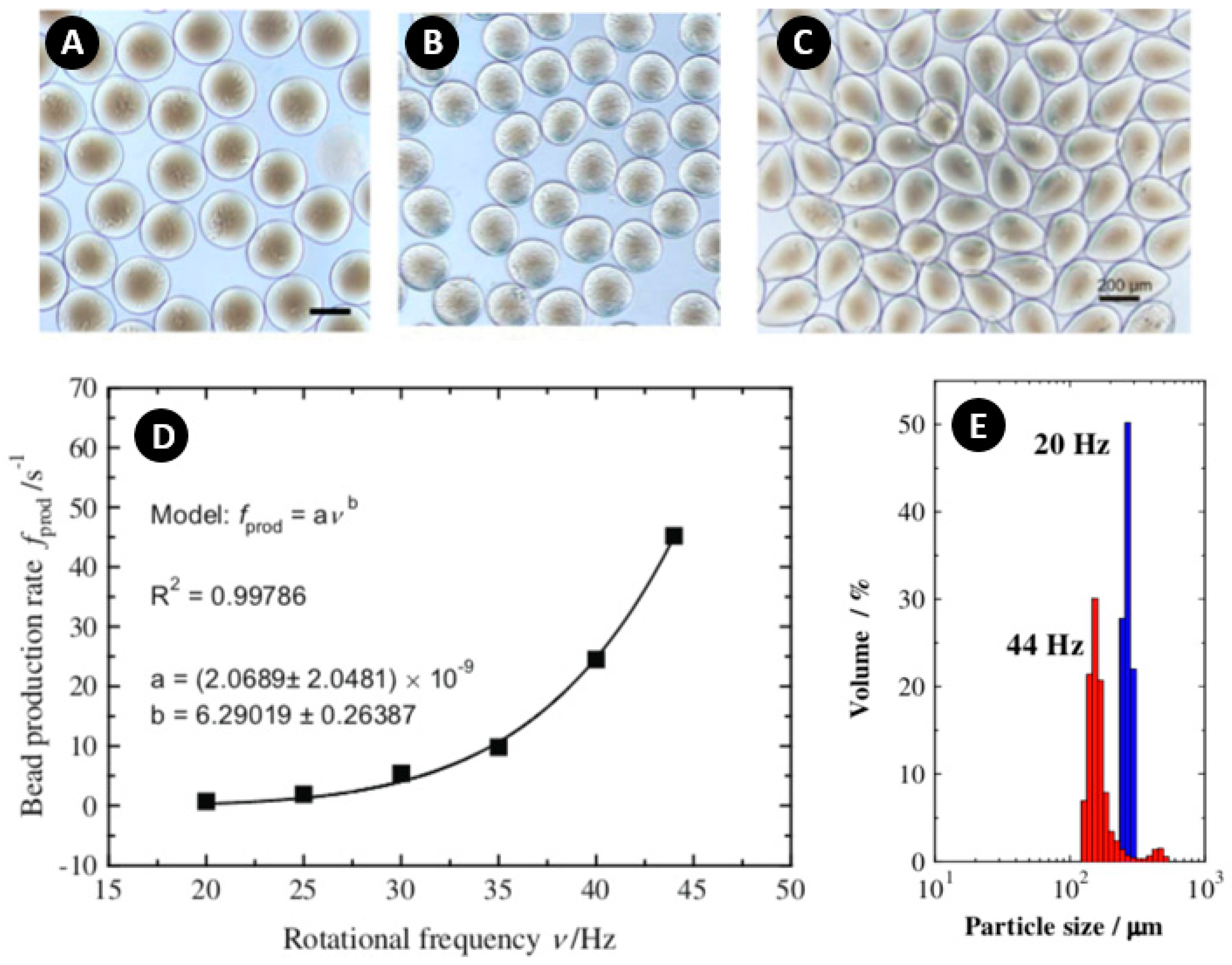
| 2% (w/w) chitosan | 10% (w/w) TPP solution at pH 4.0. | 257~148 | 127 | 22~15 | 0.7~45.2 per second | 93~452 g 20~44 Hz | [115] |
| 2~6% w Na-alginate | CaCl2 | 800~180 | 127 | 16~7 | Up to 600 per second and channel | 5~28 Hz | [42] |
| Aqueous solution (PCR mixture) | A binary mixture of 93% (v/v) isopropyl palmitate and 7% (v/v) ABIL EM180 | 165~45 | 6.2 | 11~3.4 | - | 1000~15,000 g | [64] |
| 1%, 1.5%, and 2% (w/v) Na-alginate | 2.5~20 wt% CaCl2 (0.5% Tween 20) for surfactant | 269~109 | Depth 40~80 Width 100~1000 | 5.6~5.2 | - | 130~515 g | [79] |
| 1.5~8% w Na-alginate | CaCl2 | - | 80 | - | 1~500 g | [69] | |
| Calcium carbonate (CaCO3) | CaCl2 | 150 | - | 4~2.7 | 170 droplet/s | 350 g | [121] |
| Material | Diameter Range (µm) | CV (%) | Rotating Acceleration/Frequency | Ref. | |
|---|---|---|---|---|---|
| Dispersed Phase | Continuous Phase | ||||
| Air | Silicone oil | - | - | variable | [127] |
| Water | Sunflower oil | 270~188 | - | 14.3~27 Hz | [63] |
| Water | Mineral oil | 80 | - | 9.2 Hz | [55] |
| Water | Sunflower oil | 211 | 2 | 7~33 Hz | [46] |
| Water | Silicon oil | - | - | 3.2~23.9 Hz | [104] |
| Water | HFE-7500 oil | - | - | 3.3~15.8 Hz | [62] |
| Water | Silicon oil | 82~90 | - | 3.3~50 Hz | [128] |
| Characteristics | Step Emulsification | Crossflow | Dispenser Nozzle | Other Methods | |||
|---|---|---|---|---|---|---|---|
| Binary Unit | Centrifugal Homogenization | Fluidic Barrier | |||||
| Diameter Range (μm) | 18~200 | 80~270 | 45~800 | 7700 | 18~35 | 280~1900 | |
| CV% | 1.4~14 | 2 | 2.7~22 | - | 20~50 | - | |
| Production Rate (per second per nozzle) | 50~2800 | - | 0.7~600 | - | - | 0.003~1 | |
| Rotating Criteria | Speed (Hz) | 0.5~100 | 3.2~50 | 5~44 | 5~20 | 50~100 | 10~20 |
| Acceleration (m/s2) | 150~1000 g | - | 1~15,000 g | - | - | - | |
| Density sensitive | Yes | No | Yes | No | No | Yes | |
| Limitations | ☑Highly density dependent (i.e., limited materials) | ☑High value of shear forces ☑High consumption of the continuous phase ☑The need of adjustment of different flow rates | ☑Limited material selection ☑Formation of tail and non-spherical particles | ☑Low production rate | ☑Low monodispersity | ☑Highly density dependent (i.e., limited materials) | |
| Strength | ☑High monodispersity ☑Fast production rate ☑low shear force ☑Simple fabrication ☑High volume-fraction emulsions ☑Low need of continuous phase fluid | - | ☑Low need of continuous phase fluid | ☑High monodispersity | ☑High production rate ☑Simple fabrication method | ☑Low shear force ☑High volume-fraction emulsions ☑Low need of continuous phase fluid | |
| Other remarks | - | - | ☑This method is mostly used for particle generation, not droplets | - | - | ☑This is a general method applicable to all different methods for generation of multiple emulsions and microparticles | |
| Applications |
Picolitre compartments for biochemical assays, preparation of cell-sized functional microbeads [73] | Complex bioassays such as the Bradford assay and DNA purification assay, (PCR) real-time DNA amplification [28] | Mechanical cell lysis (mechanical lysis of mpkCCD mouse kidney cells) [129] | Cell encapsulation, drug delivery, and digital PCR [131] | |||
© 2020 by the authors. Licensee MDPI, Basel, Switzerland. This article is an open access article distributed under the terms and conditions of the Creative Commons Attribution (CC BY) license (http://creativecommons.org/licenses/by/4.0/).
Share and Cite
Azimi-Boulali, J.; Madadelahi, M.; Madou, M.J.; Martinez-Chapa, S.O. Droplet and Particle Generation on Centrifugal Microfluidic Platforms: A Review. Micromachines 2020, 11, 603. https://doi.org/10.3390/mi11060603
Azimi-Boulali J, Madadelahi M, Madou MJ, Martinez-Chapa SO. Droplet and Particle Generation on Centrifugal Microfluidic Platforms: A Review. Micromachines. 2020; 11(6):603. https://doi.org/10.3390/mi11060603
Chicago/Turabian StyleAzimi-Boulali, Javid, Masoud Madadelahi, Marc J. Madou, and Sergio O. Martinez-Chapa. 2020. "Droplet and Particle Generation on Centrifugal Microfluidic Platforms: A Review" Micromachines 11, no. 6: 603. https://doi.org/10.3390/mi11060603