Review

A Review of Passive Micromixers with a Comparative Analysis

Department of Mechanical Engineering, Inha University, Incheon 22212, Korea
*
Author to whom correspondence should be addressed.
These authors contributed equally to this work.
Current address: Department of Industrial and Production Engineering, Jashore University of Science and Technology, Jessore 7408, Bangladesh
Micromachines 2020, 11(5), 455; https://doi.org/10.3390/mi11050455
Submission received: 2 March 2020 / Revised: 24 April 2020 / Accepted: 24 April 2020 / Published: 27 April 2020
(This article belongs to the Special Issue Analysis, Design and Fabrication of Micromixers)

Abstract

:
A wide range of existing passive micromixers are reviewed, and quantitative analyses of ten typical passive micromixers were performed to compare their mixing indices, pressure drops, and mixing costs under the same axial length and flow conditions across a wide Reynolds number range of 0.01–120. The tested micromixers were selected from five types of micromixer designs. The analyses of flow and mixing were performed using continuity, Navier-Stokes and convection-diffusion equations. The results of the comparative analysis were presented for three different Reynolds number ranges: low-Re (Re ≤ 1), intermediate-Re (1 < Re ≤ 40), and high-Re (Re > 40) ranges, where the mixing mechanisms are different. The results show a two-dimensional micromixer of Tesla structure is recommended in the intermediate- and high-Re ranges, while two three-dimensional micromixers with two layers are recommended in the low-Re range due to their excellent mixing performance.

1. Introduction

Microfluidics is becoming more important in many chemical and biological applications [1,2,3]. Diffusion instead of turbulence governs the mixing of fluid species at the micrometer scale, and the mixing process is prolonged. Consequently an enhanced fluid mixing capability is essential for the design of micromixers. Micromixers are necessary parts of lab-on-a-chip (LOC) devices and micro-total analysis systems (μ-TAS) [4,5,6,7,8,9,10]. In various microfluidic applications, the mixing capability of micromixers may affect the overall performance of the entire systems. For example, fast mixing of cells, reagents, and organic solutions are essential in many bioengineering and biochemical systems [11,12,13]. A notable example of the mixing of reagents or organic solutions is nanomaterial synthesis [14,15]. Efficient mixing significantly improves the detection sensitivity and reduces the analysis time [16,17].
Based on the mixing mechanisms, micromixers generally come under two categories: active and passive types. In active micromixers, flow perturbation is created using external energy sources, such as magnetic fields, electric fields, and ultrasonic vibration. Additionally, active micromixers require a control mechanism, which makes the entire system more complex and creates difficulties in fabrication and operation. However, acoustofluidic devices [18,19,20] showed promising prospects for lab-on-a-chip applications and in the bio-medical diagnostic field. Sharp-edge-based acoustic active micromixers [20,21] with serpentine-like channels were recently fabricated in a simple manner and used for versatile applications. Furthermore, an active acoustic-based micromixer [18] also achieved combined pumping and mixing in a single device; in other words, it required no external source of fluid pumping.
Contrarily, no external energy source except for pumping of fluids is required in passive micromixers, and the mixing is performed by molecular diffusion and chaotic advection. Chaotic advection is generally created by modifying the microchannel geometry to reduce the diffusion length and maximize the interfacial area between the fluids by manipulating or reorganizing the fluid flow. Thus, compared with active micromixers, passive micromixers are economical, convenient, and can easily be incorporated into LOC systems [10,22,23,24]. Passive micromixers are also used as ‘concentration gradient generators’ for biological and pharmaceutical applications [25,26]. Recently, various passive mixers have been proposed to accomplish effective mixing. Chaotic flows induced by repeated perturbations of the fluid flow can significantly increase the performance of micromixers [27,28,29], and are generated by several different microchannel geometries: two-dimensional (2D) structures [30,31,32,33,34,35,36,37,38,39,40,41], three-dimensional (3D) serpentine structures [42,43,44,45,46,47,48,49], patterned groove structures [29,50,51,52,53,54,55,56,57,58], 2D and 3D split-and-recombination (SAR) structures [59,60,61,62,63,64,65,66,67,68,69,70,71,72,73,74,75,76,77,78,79,80,81], and two-layer crossing channels [82,83,84,85,86,87,88,89].
Several review articles have introduced a variety of passive micromixers with their mixing mechanisms [6,24,90,91,92,93,94,95]; these micromixers have various dimensions and working conditions (e.g., Reynolds number). However, quantitative comparisons of their mixing performance are rarely found in the literature, even though designers would benefit from the information on mixing performance of different micromixers under the same geometric and working conditions. Such information will assist in the selection of suitable designs to meet specific requirements for different processes [92].
Quantitative comparisons have been performed only for specific types of passive micromixers. Falk and Commenge performed a comprehensive study of conventional T-type micromixers and micromixers based on the concept of SAR or multi-lamination through the Villermaux-Dushman test reaction [96]. They analyzed and compared the mixing efficiencies of the micromixers while considering Reynolds number and power dissipation per unit mass of the liquid. Viktorov et al. presented a comparative analysis of three passive micromixers (tear-drop, Y-Y, and H-C micromixers) in a wide range of Reynolds numbers [97]. They conducted a numerical simulation and experimental analysis to evaluate the mixing performance at Reynolds numbers ranging from 1 to 100. Bošković et al. analyzed and compared the characteristics of the residence time in three different passive micromixers (micromixers with 3D serpentine structure, staggered herringbone grooves, and split and recombine (SAR) structure) [98]. The microstructures with similar channel designs were analyzed across a wide range of Reynolds numbers (0.3 ≤ Re ≤ 110).
As mentioned above, a variety of micromixer designs have been developed so far, but no one has reported a quantitative evaluation of the micromixers operating at the same conditions, which is necessary for the selection of effective micromixers under different flow conditions in various microfluidic applications. Therefore, in the present work, a review of a wide range of existing passive micromixers is presented and a comparative analysis of selected micromixers was performed under the same working fluids, Reynolds number, and axial channel length for a quantitative comparison among them. For the comparative analysis, ten micromixers were selected among the high-performance micromixers found in the literature, which cover five typical micromixer designs. These micromixers achieved efficient mixing with different mixing mechanisms or their combinations, as explained in Section 2. The numerical analyses of mixing and fluid flow were performed using Navier-Stokes and advection-diffusion equations for momentum and mass transports, respectively. The comparison was performed in a Reynolds number range of 0.01–120.

2. Mixing Mechanisms of Micromixer Types and Selected Micromixers

In the last two decades, a number of passive micromixers involving different microchannel designs have been proposed, as introduced in the previous section. The microchannel designs can be categorized into five types, as shown in Table 1. For the quantitative comparison in this work, ten representative micromixers (M-1 to M-10) were selected as shown in Table 2, and Figure 1, Figure 2, Figure 3, Figure 4, Figure 5, Figure 6, Figure 7, Figure 8, Figure 9 and Figure 10 show that their schematics. M-1 to M-4 are 2D planar designs, and M-5 to M-10 are 3D designs. To compare the mixing performances at an equal axial length, which refers to the length of the channel in the x-direction between the start of the mixing unit and the micromixer exit, the number of mixing units in each micromixer was changed from the original number as indicated in each figure caption. The dimensions of the mixing unit in each micromixer were the same as those in its original design. The mixing capability was evaluated at each micromixer exit (5050 µm (Lt) downstream of the start of the mixing unit) for the comparison.

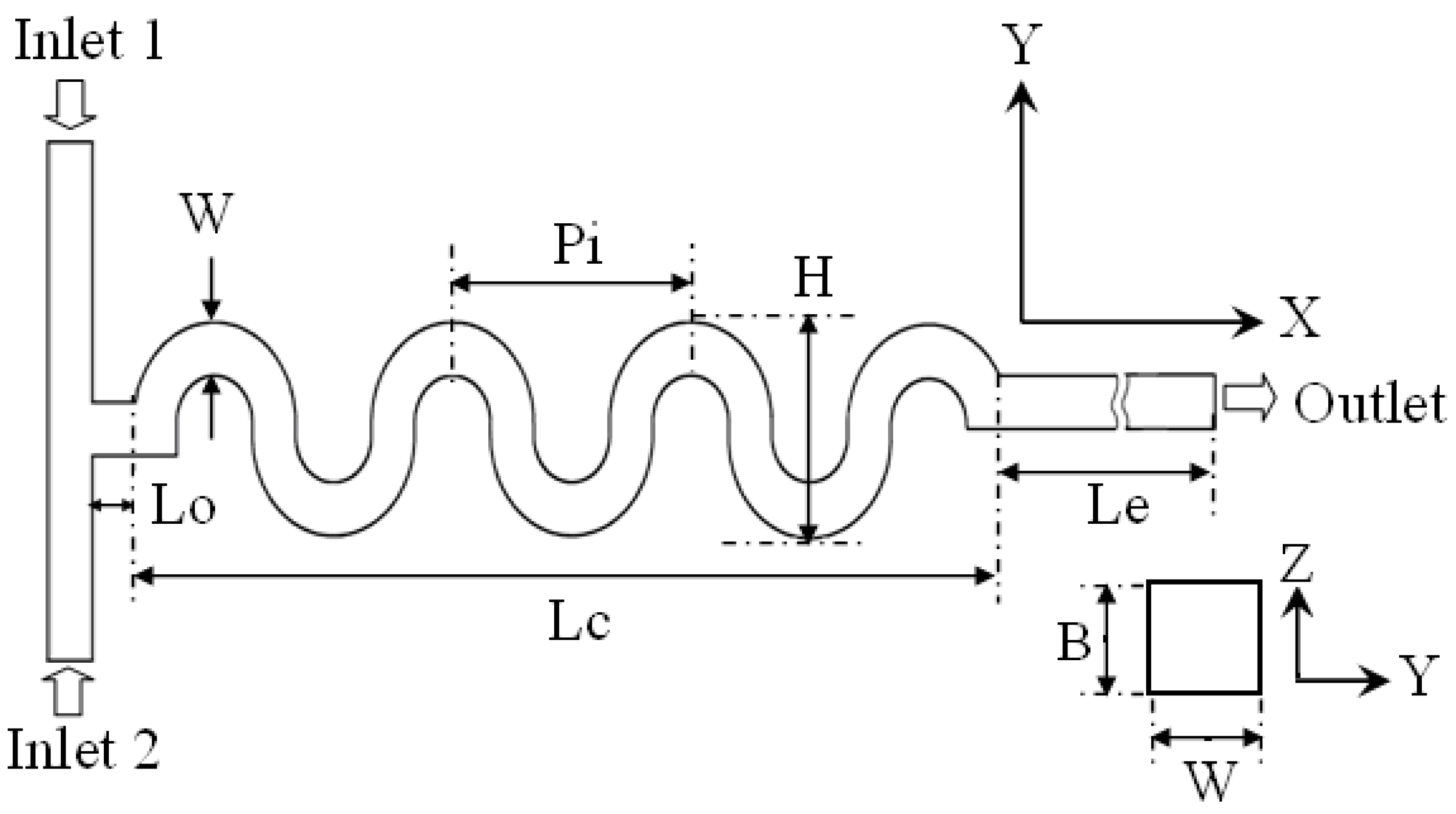
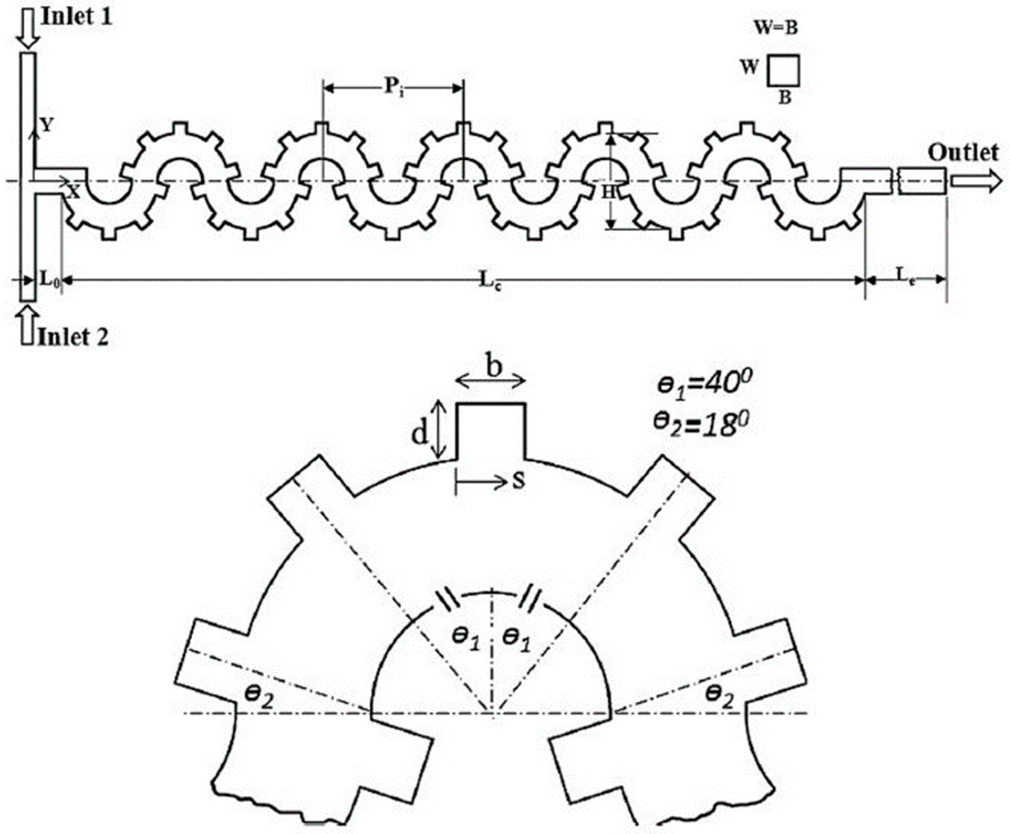
2.1. 2D Designs Using Serpentine, Spiral, and Curved Helical Channels (Type 1)

2D planar micromixer designs have an advantage of simplicity in the fabrication compared to the complex 3D designs. Mixing in 2D serpentine, spiral, and curved helical channels [30,31,32,33,34,35,36,37,38,39,40,41] mainly depends on the advection caused by the secondary flow or Dean vortices created by the inertia force. The performance of this type (type 1 in Table 1) of micromixers improves as the Reynolds number increases due to the dependence of secondary flow/Dean vortices on Reynolds number [78]. Hossain et al. [40] and Alam and Kim [41] conducted numerical investigations of mixing in 2D planar micromixers, M-1 (Figure 1) and M-2 (Figure 2), respectively. Hossain et al. [40] estimated the mixing performance of three serpentine passive micromixers (square-wave, zigzag, and curved shape microchannels) across a wide range of Reynolds numbers (0.267–267). Alam and Kim [41] introduced rectangular grooves on the sidewalls of a curved serpentine channel to evaluate mixing in a Reynolds number range of 0.5–90.

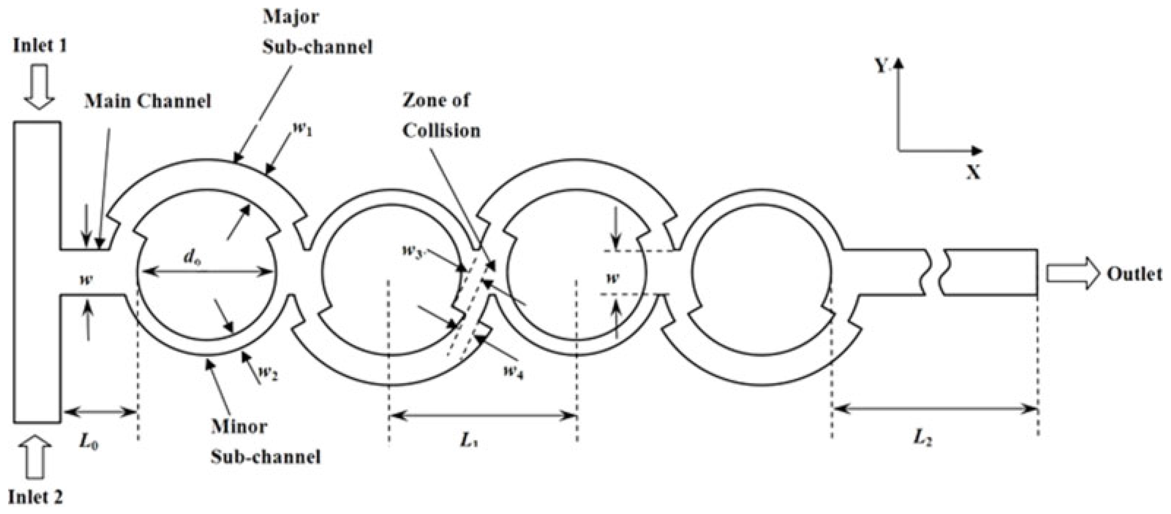
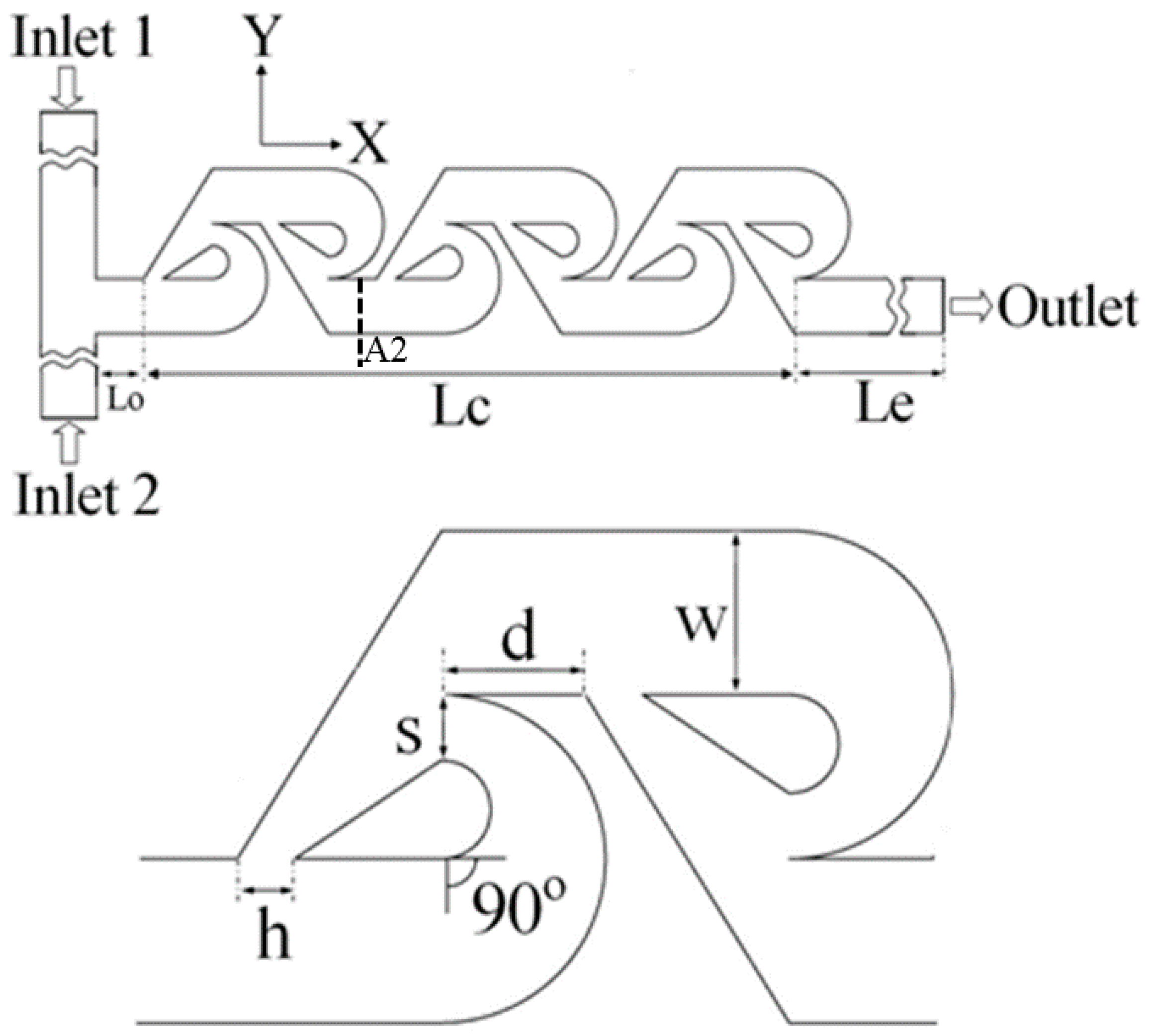
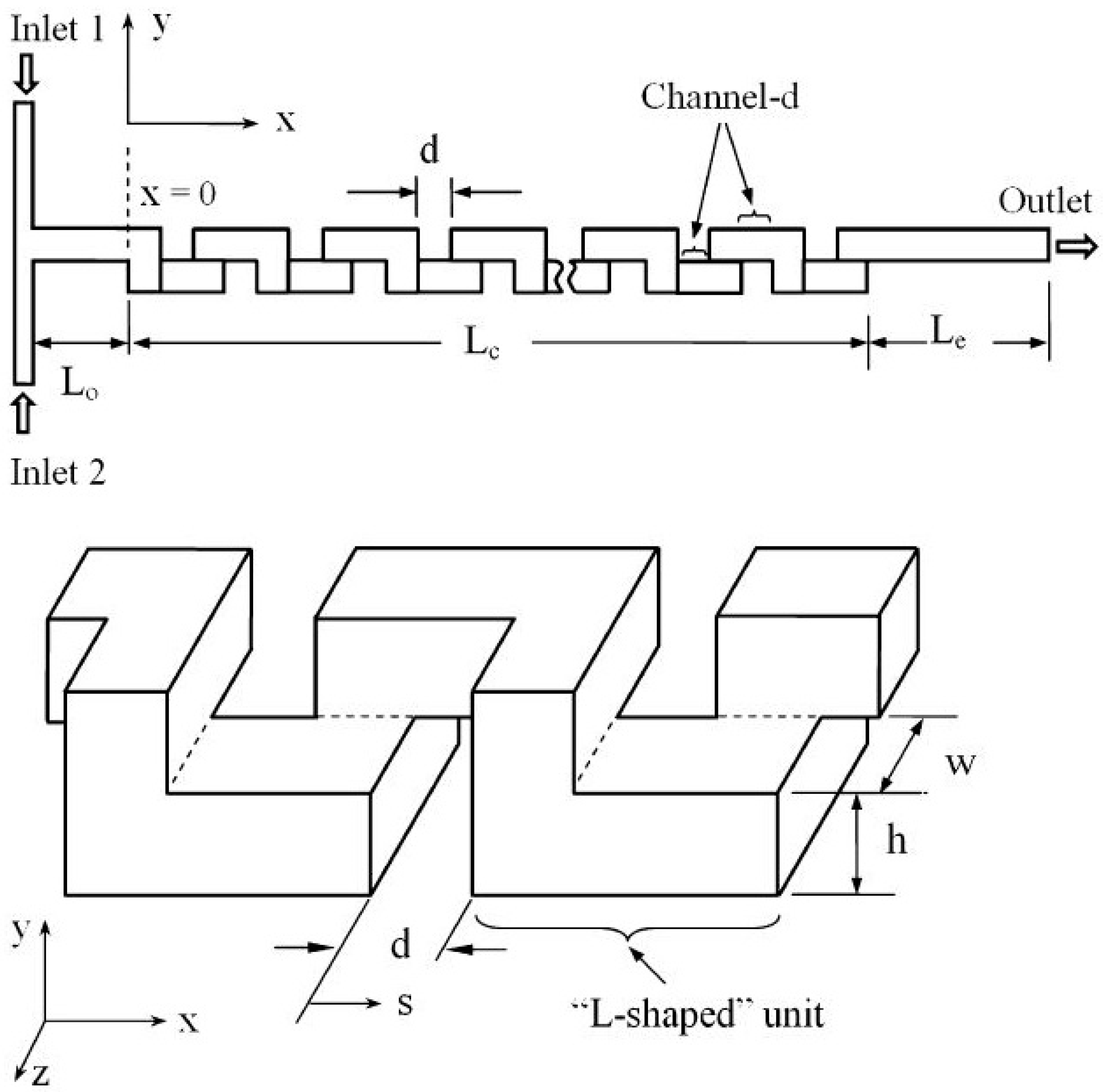
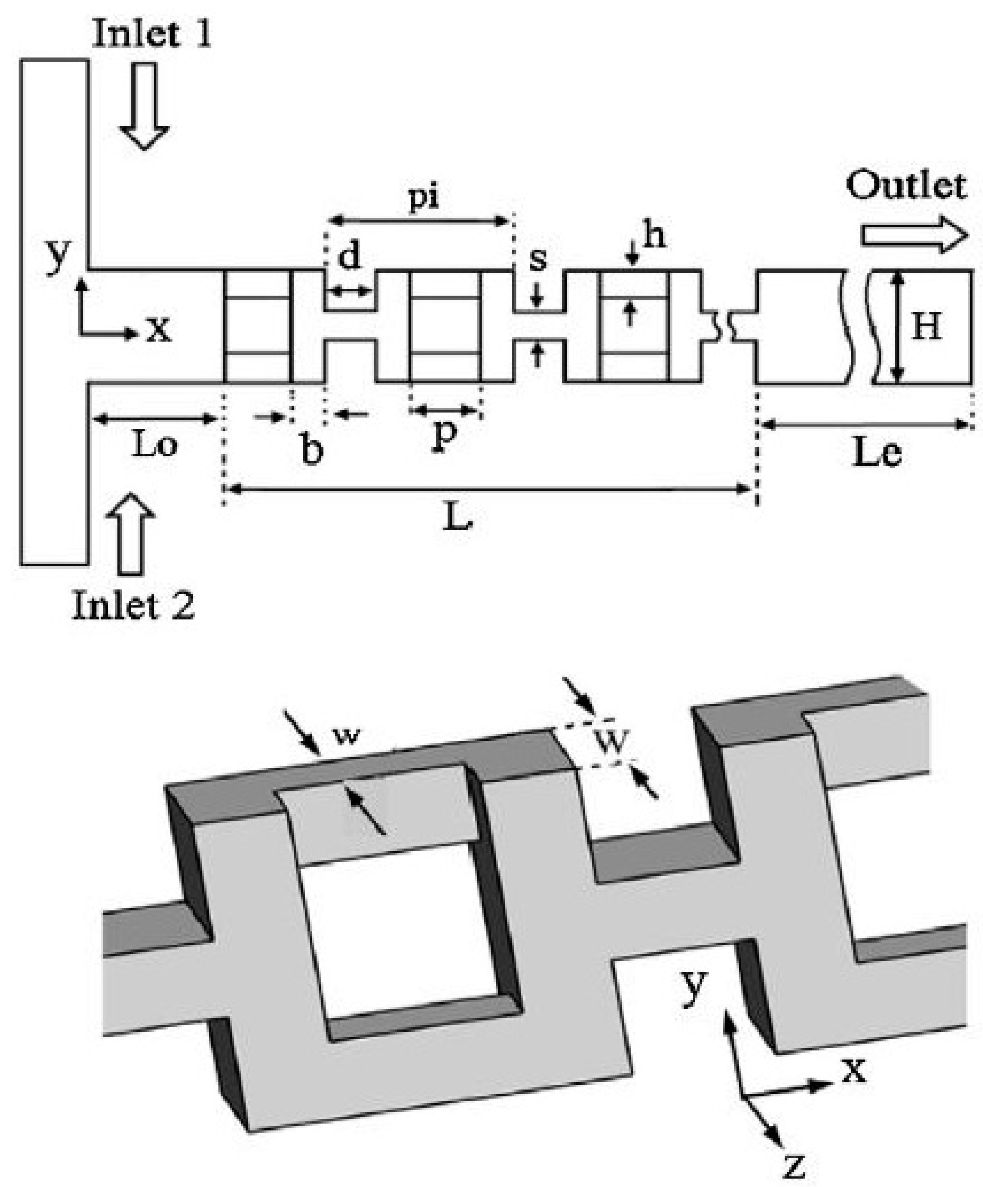
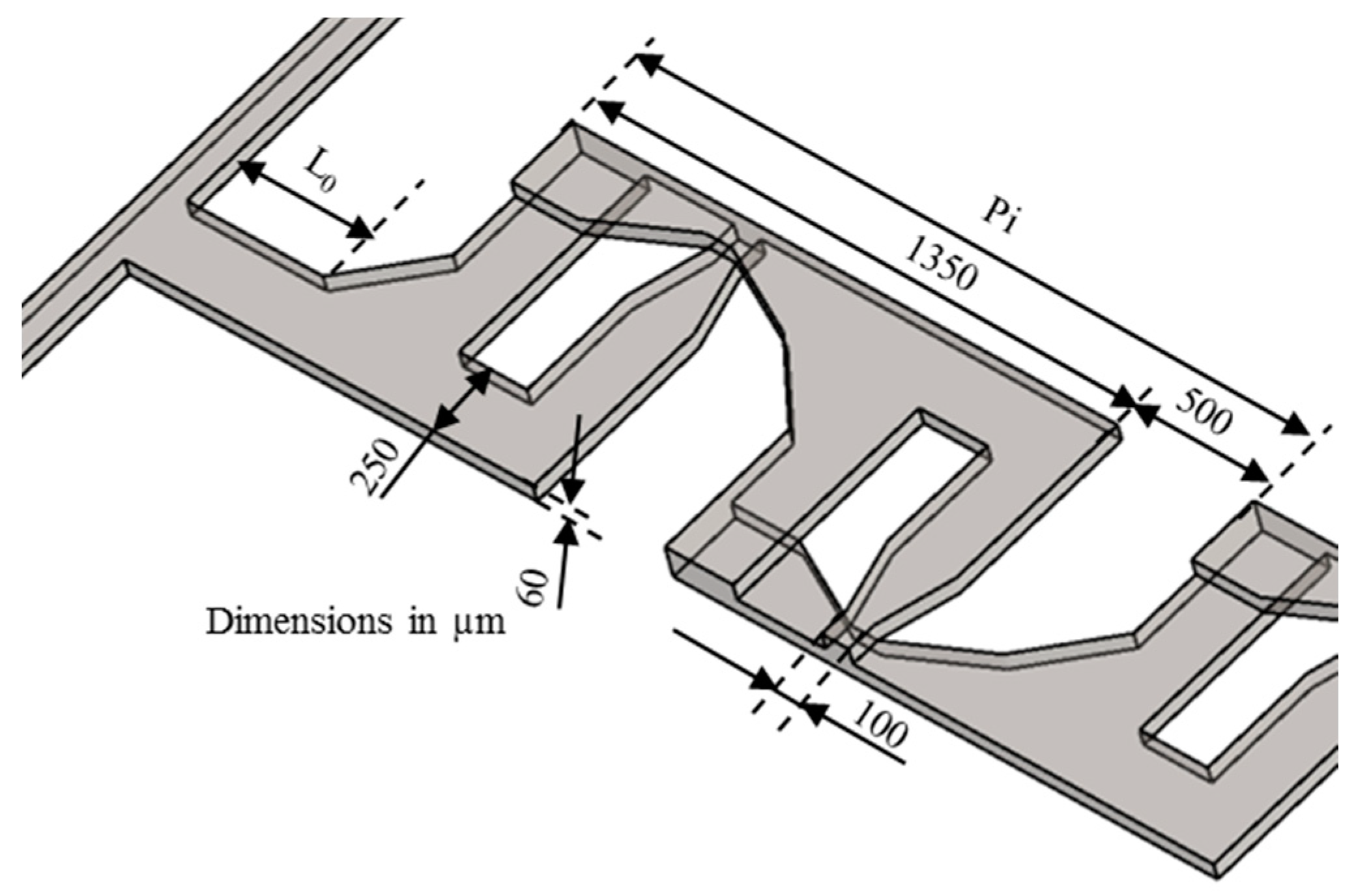
2.2. 2D Designs with SAR Structures (Type 2)

A variety of planar SAR micromixers (type 2 in Table 1) involving multi-lamination and inertial flow have been developed [68,69,70,71,72,73,74,75,76,77,78,79]. The SAR micromixers generate multi-laminating flow patterns successively with the three underlying flow mechanisms of splitting, recombination, and rearrangement [6]. Dean and expansion vortices are generated through curved channels and expansion-contraction at high Reynolds numbers [70,71,76].
Ansari et al. [76] proposed and analyzed a micromixer using asymmetrical splits and collisions of fluid streams. The lowest mixing performance was obtained with uniform sub-channel widths representing balanced collision over a range of Reynolds numbers. Induced Dean vortices at the interfaces in the curved sub-channels and SAR were found to enhance the mixing performance. Xia et al. [70] designed an asymmetric SAR micromixer with a fan-shaped cavity to achieve efficient mixing by the synergistic effect of expansion vortices and Dean vortices in the fan-shaped cavity along with unbalanced collision in the recombination zone. The selected micromixer, M-3 [68] shown in Figure 3, represents a planar asymmetric SAR (P-ASAR) design with outward protruded sub-channels, which is an improved form of a previous micromixer [76]. In this micromixer, the mixing performance was enhanced by the synergistic effect of unbalanced inertial collisions, expansion vortices, and Dean vortices on mixing.
Xia et al. [74] designed and fabricated a 2D planner micromixer consisting of a series of gaps and baffles in a simple microchannel. A sudden contraction provided by a gap accelerates the fluid stream and produces symmetrical expansion vortices. The accelerated fluid stream is separated by a baffle, and the same flow pattern is repeated. The synergistic effects of abrupt contraction and expansion, multiple SAR, and multiple secondary vortices increase the interfacial area of the fluids, resulting in excellent mixing performance. Hong et al. [72] proposed an innovative micromixer with a 2D modified Tesla structure (M-4) shown in Figure 4, which takes advantage of the Coanda effect. The splitting and reuniting of the fluids effectively reduce the diffusion path between the fluid streams. The structure causes chaotic flow by the collision of the fluid streams on redirection, and improves mixing. Hossain et al. [77] improved the efficiency of a modified Tesla micromixer through an optimization.

2.3. 3D Design with Serpentine and/or SAR Structures (Type 3)

Several micromixers involving 3D serpentine and/or SAR structures [42,43,44,45,46,47,48,49,59,60,61,62,63,64,65,66,67,80,81] (type 3 in Table 1) have been proposed. The 3D serpentine path induces a stirring flow at each bend and generates a secondary flow to enhance mixing [43,45]. The SAR structure provides lamination that decreases the diffusion path and enhances mixing at low Reynolds numbers [65]. The secondary flow combines with the axial flow, and creates chaos by stretching and folding the fluid interface [47].
Ansari and Kim [45] investigated the effects of flow and geometric parameters on the mixing performance of an L-shaped 3D serpentine micromixer (M-5) shown in Figure 5. Hossain and Kim [59] proposed a 3D serpentine SAR micromixer composed of O- and H-shaped units (M-6) shown in Figure 6. The O- and H-structures split and recombine the fluid streams repeatedly. Continuous splitting and recombining of the fluid streams generate chaotic mixing. Kim et al. [80] proposed a chaotic-mixing-based serpentine lamination micromixer (SLM) composed of F-shaped mixing units. The SLM structure combines two general chaotic mixing mechanisms: SAR induced by the mixing segments and chaotic advection induced by the overall 3D serpentine channel path. Park et al. [81] proposed a geometrical modification of SLM to improve the mixing efficiency. Figure 7 shows the improved SLM (ISLM) (M-7), where the original F-shaped mixer is altered at the recombination region. The reduced cross-sectional area enhances the vertical lamination by enhancing the local advection, consequently improving the mixing performance.

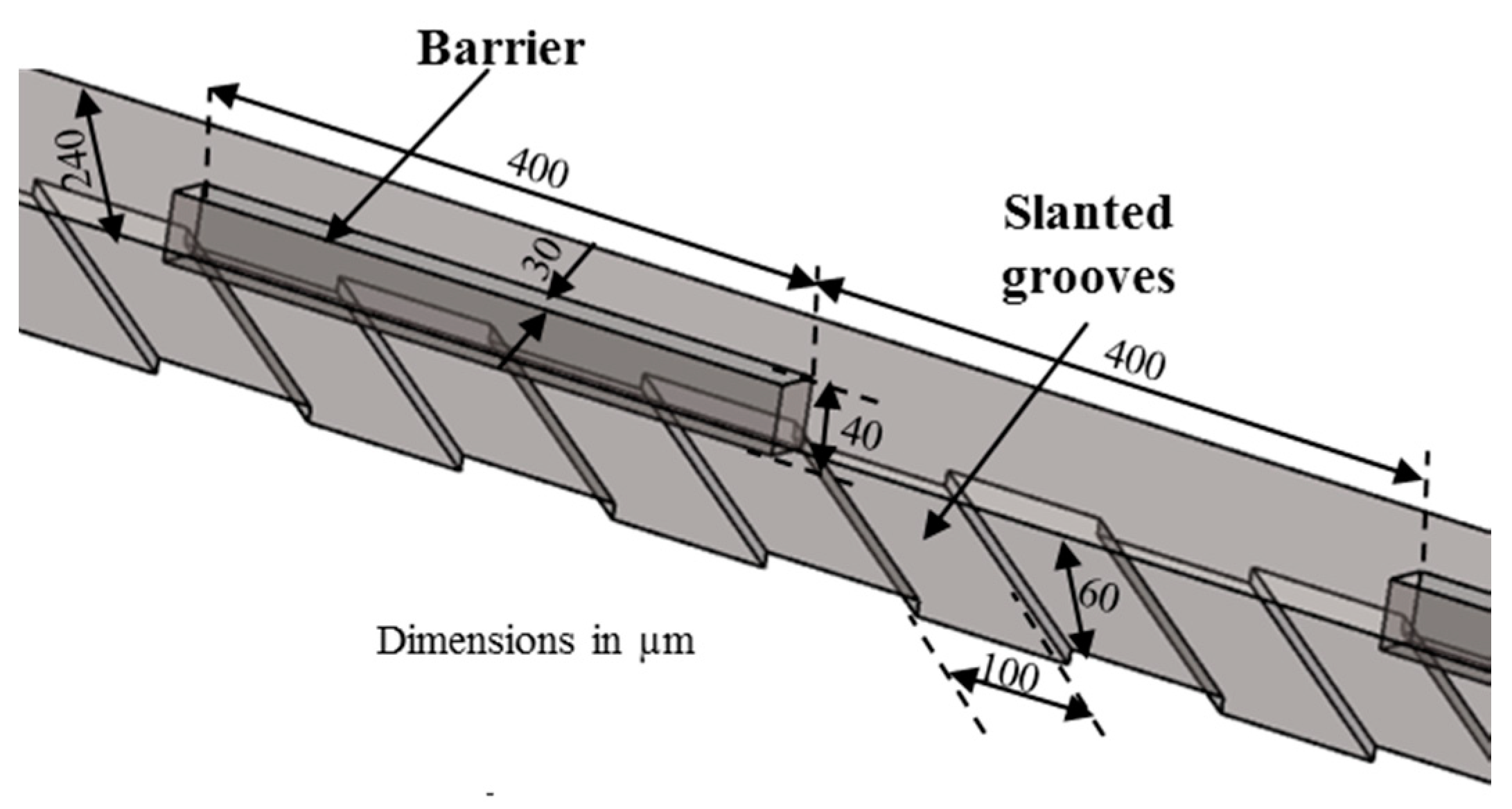
2.4. 3D Design with Patterned Grooves (Type 4)

Patterned grooves on the channel wall were also used to promote mixing in microchannels [29,50,51,52,53,54,55,56,57,58] (type 4 in Table 1). The grooves induce 3D helical flow in the microchannels, which promotes mixing. Kim et al. [58] designed a micromixer with rectangular barriers on the top of the slanted grooves (M-8) shown in Figure 8. The periodically located barriers on the top wall are capable of creating velocity fields characterized by two elliptic points and a hyperbolic point alternately within the helical motion produced by the grooves at the bottom, which results in enhancement of chaotic mixing.

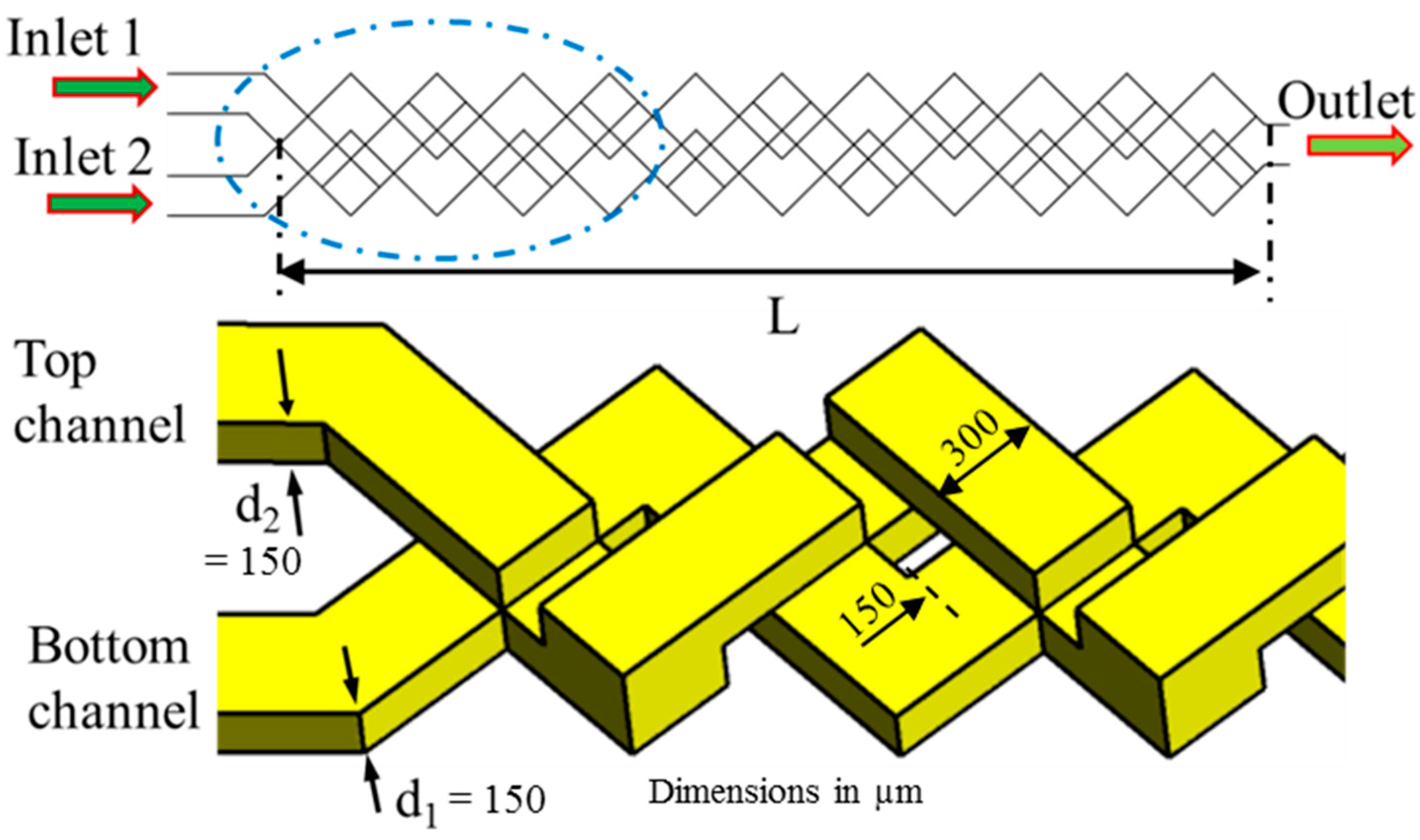
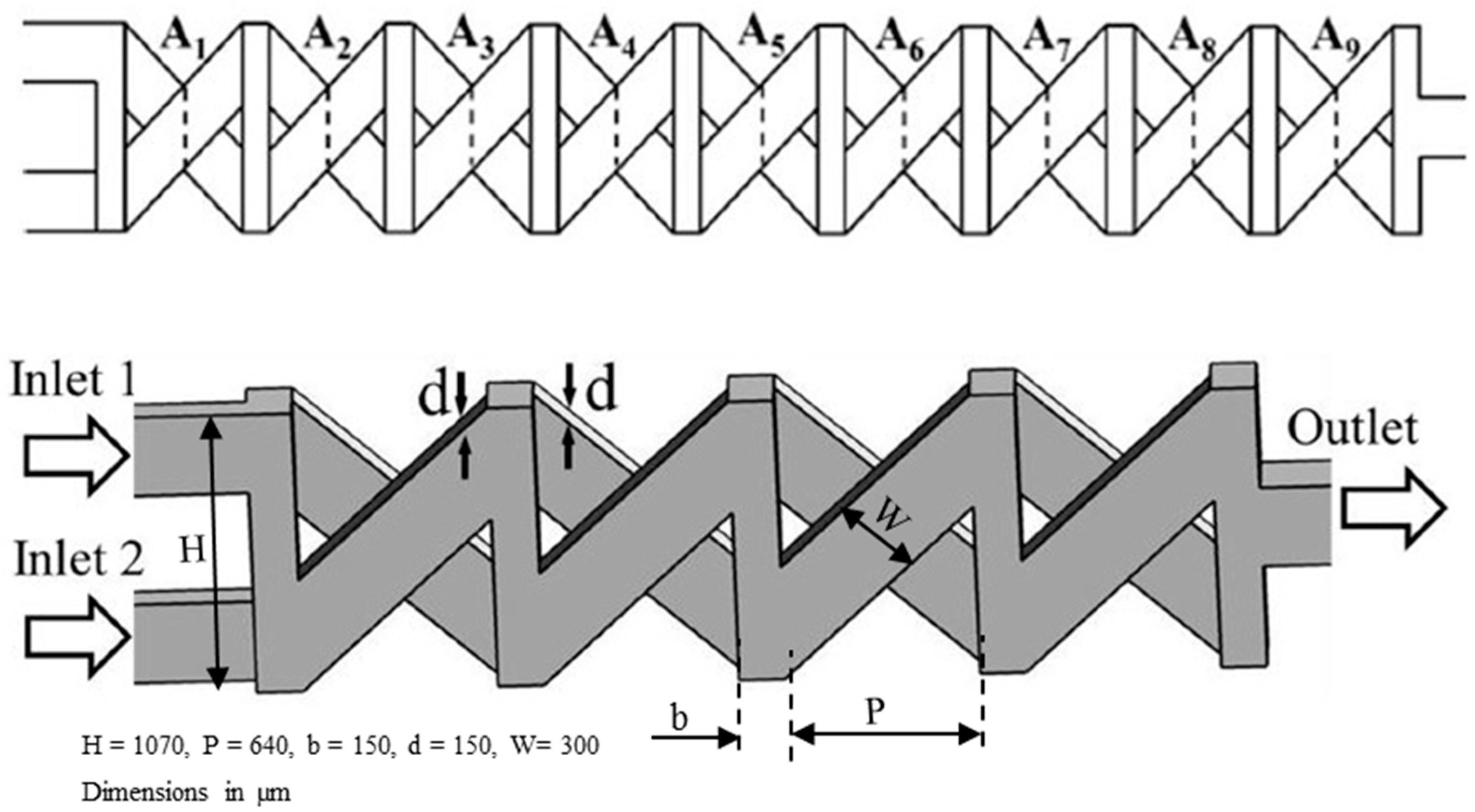
2.5. 3D Designs with SAR Two-Layer Crossing Channels (Type 5)

3D micromixers with SAR two-layer crossing channels (type 5 in Table 1) have achieved remarkable mixing performance [82,83,84,85,86,87,88,89]. The crossing channels produce chaotic flow due to repeated splitting, stretching, rotating, and folding processes. A saddle-shaped flow structure is produced despite low Reynolds number. Hence, the chaotic flow inside the crossing channels does not depend on the fluid inertia [84].
Xia et al. [84] designed a chaotic micromixer (M-9) using 3D X-shaped crossing channels (TLCCM) shown in Figure 9. The micromixer exhibited an outstanding mixing efficiency of 96% at a low Reynolds number (Re = 0.2). Hossain et al. [89] further analyzed the responses of the flow structure and mixing performance to the variations in geometric parameters of TLCCM.
Recently, Hossain et al. [87] designed a chaotic micromixer with two-layer serpentine crossing microchannels (M-10) based on the mixing mechanism of TLCCM (Figure 10) to improve the mixing capability at low Reynolds numbers. This micromixer consists of two layers of serpentine channels. The bottom and top layers contain a series of N- and inverse N-shaped segments, respectively. The fluid streams are interconnected at the vertical sections and the intersections of the crossing channels. The fluid flow in successive mixing modules produces chaotic advection through continuous splitting, recombination, enlarging, and folding of the fluid streams.

3. Analysis Methods

The flow inside the microchannel was assumed to be steady, incompressible, laminar, and Newtonian. The continuity (Equation (1)), momentum (Equation (2)), and convection-diffusion (Equation (3)) equations were solved numerically for the flow and mixing analysis. The CFD software ANSYS CFX 15.0® [99] employs a coupled solver and finite volume technique to discretize Equations (1)–(3):
· V = 0
( V · ) V = 1 ρ P + ν 2 V
( V · ) C = D 2 C
where V , C, D, ρ, P, and ν are the velocity, dye concentration, diffusion coefficient, density, pressure, and kinematic viscosity, respectively.
A finite-volume-based commercial code ANSYS CFX 15.0® [99] has been used to solve the governing differential equations. Tetrahedral meshes were generated using ICEM CFD® for the grid systems. The boundary conditions were the uniform velocity profiles at the inlets, zero static pressure at the outlets, and no-slip conditions at the channel walls. Dye-water solution and water, both having the properties of water at 25 °C (dynamic viscosity: 8.8 × 10⁴ kg/m·s; density: 997 kg/m3) were used as the working fluids. The numerical solution was assumed to be converged as root-mean-squared residual values for momentum and mass fraction reach a value less than 1.0 × 10⁻⁶. The diffusivity constant of the solution was fixed to be 1.0 × 10⁻¹⁰ m2/s. Reynolds number was calculated using the hydraulic diameter and average velocity at the inlets.
The numerical methods same as used in the present work, were validated comparing with experimental results for a variety of micromixers in previous works [40,41,45,54,55,57,59,69,75,76,77,79,87,88,89].
The mixing index was estimated by calculating the variance of concentration on a particular transverse plane normal to the fluid flow. The mass fraction variance was determined as:
σ = 1 N i = 1 N ( c i c ¯ m   ) 2
where N denotes the number of data points on the cross-sectional plane, c ¯ m   is the optimal mass fraction, and c i is the mass fraction at a point i. The mixing index was defined as:
M = 1 σ σ max
where σmax is the maximum variance over the data range. The mixing index ranges from zero (wholly separated fluid streams) to unity (complete mixing).
The other mixing performance parameter, mixing cost (MC) [100] that takes pressure drop into account along with the mixing index was defined as follows: where N denotes the number of data points on the cross-sectional plane, cm is the optimal mass fraction, and ci is the mass fraction at a point i. And, the mixing index was defined as:
mixing   cos t M Δ P
where ΔP denotes the pressure drop. A high value of MC indicates an efficient micromixer.

4. Results and Discussion

4.1. Grid Refinement Test

Optimal numbers of computational grid nodes were determined after performing exhaustive grid refinement tests at Re = 40 for all the micromixers. Mixing index at the exit was selected as an indicator for choosing the optimal grids. The number of grid nodes from 3.86 × 10⁵ to 2.55 × 10⁶ were tested in the grid refinement tests. The optimum numbers of nodes that were selected for the ten micromixers varies from 1.55 × 10⁶ to 2.21 × 10⁶, as listed in Table 3.

4.2. Quantitative Comparisons in Different Reynolds Number Ranges

The examined range of Reynolds numbers (Re = 0.01–120) was divided into three sub-ranges: low-Re (Re ≤ 1), intermediate-Re (1 < Re ≤ 40), and high-Re (Re > 40) ranges. One of the primary purposes of the present comparative analysis was to find efficient micromixers in each Re range. Evaluated values of mixing index (M), pressure drop ( Δ P ), and mixing cost (MC) for each micromixer are presented in Table 4, Table 5 and Table 6, respectively.
Figure 11 shows the general trend of the mixing index variation with Reynolds number for the curved micromixer, M-1 [40]. At low Re (Re ≤ 1), low velocity of the fluid stream causes a long residential time of the fluids within the microchannel, which provides sufficient time for diffusive mixing. The mixing deteriorates rapidly as Reynolds number increases due to the reduction in the residential time, reaching a minimum at around Re = 1, where the residential time is inadequate, and the transverse flow is still ineffective for generating the secondary flow. Thus, the mixing index remains at a low level. However, beyond this Re, the residence time reduces further, but the secondary flow becomes active. Thus, mixing starts to increase with Reynolds number. The specific variation of the mixing index with Reynolds number strongly depends on micromixer configuration, but the trends are similar for different passive micromixers.

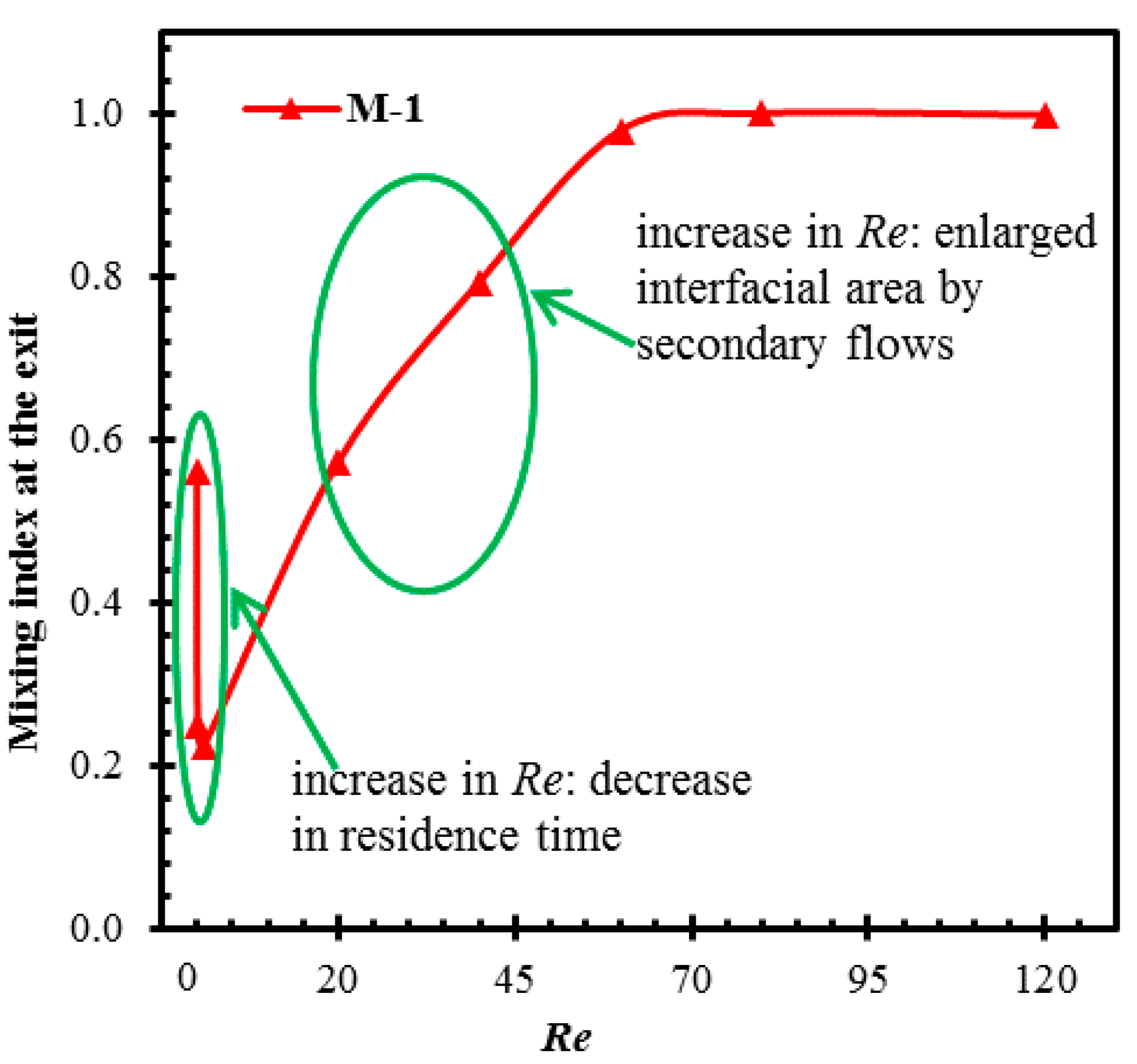
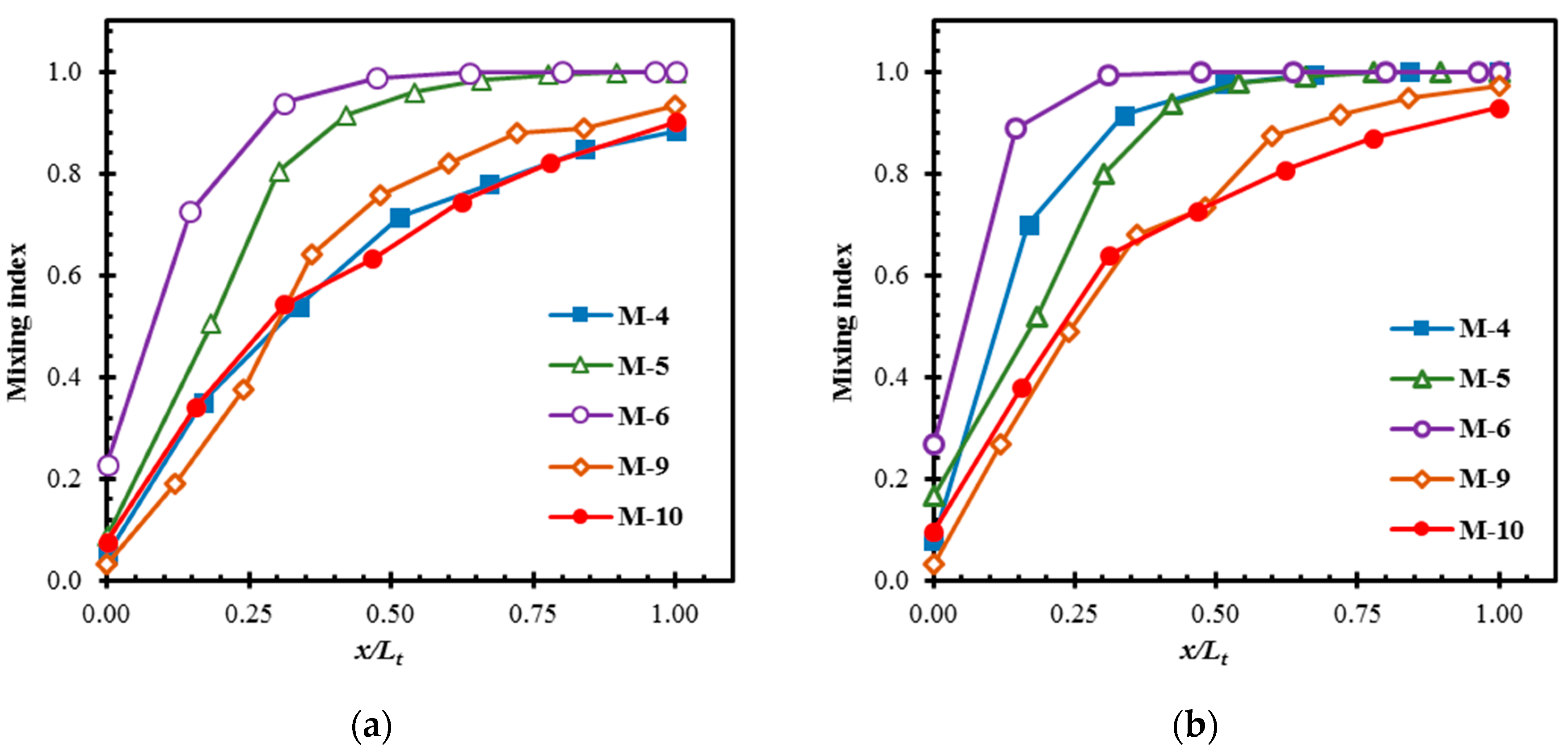
4.2.1. Mixing in Low-Re Range (Re ≤ 1)

In the low-Re range, mixing in passive micromixers is limited by molecular diffusion. Therefore, the mixing in this range mainly depends on the residential time of the working fluids in the micromixer. Mechanical stirring is not an effective method for enhancing mixing [36] because the secondary flow is hardly induced in this range. Thus, it is very challenging for researchers to design an efficient micromixer at this low-Re range.
It is found from Table 4 that, among the 2D micromixers (M-1 to M-4), the mixing indices at the exits of the curved micromixer (M-1) and the curved micromixer with rectangular grooves (M-2) are higher than the others at Re = 0.01 (M = 0.560 and 0.554, respectively). Interestingly, in this Reynolds number range, M-1 shows similar mixing performance as M-2. This is because, at low Reynolds numbers, mixing depends on molecular diffusion, and thus, geometric modification of the 2D planar micromixer is not effective in enhancing the mixing. The mixing index strongly depends on the time for which the working fluids remain in the micromixer. Hence, the mixing indices of these micromixers decrease as the Reynolds number increases up to 1. This trend does not only apply to the 2D micromixers but also to most of the tested micromixers.
The SAR micromixers (M-3 and M-4) generally show lower mixing than the micromixers with 2D serpentine structures (M-1 and M-2) in this range. However, the pressure drops are much lower in SAR micromixers, as shown in Table 5. It is observed that M-4 shows a 16.9% lower mixing index at the exit with a 65% lower pressure drop, as compared to M-1 at Re = 0.01. Among the 2D mixers, M-1, M-2, and M-4, showing high mixing indices, M-4 represents the highest MC values in the low-Re range, as shown in Table 6. M-3 shows the worst mixing performance among the tested micromixers in this range.
As shown in Table 4, the 3D micromixers using SAR with two-layer crossing channels (M-9 and M-10) achieve remarkable mixing performance at low Reynolds numbers. M-9 and M-10 show mixing indices over 0.90 in the entire low-Re range, while M-7 is only the micromixer which shows a mixing index over 0.90 (at Re = 0.01) in this Re range among the remaining micromixers. This is due to the generation of saddle-shaped flow structure in M-9 and M-10 at all Reynolds numbers, while in M-7, mixing decreases with the increase in Reynolds number due to diffusion dominant mixing. M-8 shows the lowest mixing indices among the 3D micromixers, which are even lower than those of some 2-D micromixers. This indicates that the mixing relying on elliptic and hyperbolic points generated through alternating barriers above the groove on the walls will require longer channel length for complete mixing.
Surprisingly, M-9 and M-10 also show the least pressure drops among the tested micromixers in the low-Re range, as shown in Table 5. Therefore, M-9 and M-10 show the highest MC values among the tested micromixers in the whole low-Re range (Table 6). In all the tested micromixers, MC decreases with increasing Reynolds number in this Re range. The micromixer M-7, which shows a not-much-lower mixing index than M-9 at Re = 0.01, shows about a 13-times-higher pressure drop with a 93% lower MC value at the same Re. Thus, the structure of 3D SAR with two-layer crossing channels is proved to be efficient in both enhancing mixing and reducing pressure drop in the low-Re range.
Figure 12 shows the developments of the mixing for M-4, M-9, and M-10 at Re = 0.01. The 2D micromixer (M-4) shows relatively slow development of mixing compared to the 3D micromixers (M-9 and M-10). Although M-9 and M-10 attain almost similar mixing at the exit, M-10 shows much faster development rate near the inlet of the micromixer. M-9 and M-10 reach a mixing index over 0.80 within 50% of the total length. M-9 attains the mixing index equal to the mixing index at the exit of M-4, within 35% of its length. This emphasizes that the 3D micromixer with an even slow development rate outperforms the 2D micromixer.

4.2.2. Mixing at Intermediate Reynolds Numbers (1 < Re ≤ 40)

In the intermediate-Re range, the fluid inertia starts to increase with Reynolds number, and generates secondary flows that play a dominant role in mixing enhancement. Hence, an increase in Reynolds number results in an increase in mixing index in most of the cases shown in Table 4.
Among the 2D micromixers, the mixing index at the exit of the Tesla micromixer (M-4) is highest at Re = 20 and 40, and M-4 achieves almost perfect mixing (M = 0.999) at Re = 40. In this micromixer, with the increase in Reynolds number, the collision of fluid streams on rejoining is strengthened, which enhances chaos in the flow and hence the mixing [72,77]. It is also observed that the M-2 shows higher mixing than M-1 at these Reynolds numbers. This is due to the increase in secondary flow caused by the grooves in M-2 [41]. At Re = 20 and 40, M-2 shows 21.3% and 8.2% higher mixing indices than M-1, and M-4 shows 27.2% and 16.5% higher mixing indices than M-2, respectively. It is also observed that M-4 shows much lower pressure drops than M-1 and M-2. M-4 shows 46.8% and 26.3% lower pressure drops with 139.1% and 58.2% higher MC values than M-2 at Re = 20 and 40, respectively. Among the 2-D micromixers, M-3 shows the lowest mixing indices (Table 4) in the intermediate-Re range, but shows the highest MC values (Table 6) due to the lowest pressure drops (Table 5). Mixing in M-3 depends upon the unbalanced inertial collision. Hence, the lowest mixing indices in M-3 can be attributed to insufficient inertial force to cause an effective collision of the fluid streams that enhances chaos in the recombination zone. It also highlights that the flow instability in the inertia-based micromixers occurs at different Reynolds numbers depending upon the microchannel designs. Hence, these micromixers can be used in different Re range depending upon the efficient mixing range.
Among the 3D micromixers, most of the micromixers perform well in intermediate-Reynolds number range except M-7 and M-8. This indicates that locally accelerated advection due to the narrowing of flow path along with SAR mechanism in M-7 and the alternating velocity field creating elliptic and hyperbolic points due to the barrier and groove configuration in M-8 are not as effective as mixing mechanisms for other micromixer designs. Especially, M-5 and M-6 show nearly perfect mixing (M = 0.999) in the whole intermediate-Re range. In this Re range, stretching and folding of the fluid interfaces is developed due to the transverse flows induced by inertial forces. It causes enlargement of the fluid interfacial area for diffusion, thereby promotes mixing [45,59]. The 3D swirling flow along with the vortical flow due to serpentine channel is present in M-7 as discussed in [81], showing 26.7% lower mixing index than M-5 and M-6 at Re = 40.
The structures of 3D SAR with two-layer crossing channels (M-9 and M-10) achieve over 90% mixing in the intermediate-Re range even though it does not show the best mixing indices among the tested cases as in the low-Re range. Although M-5 and M-6 show the same mixing indices, the pressure drops in M-6 are approximately 22 times higher as compared to M-5 at Re = 20 and 40, and thus M-5 has much higher MC values than M-6. M-10 shows 9.8% and 7.0% lower mixing indices and 84.0% and 86.0% lower pressure drops compared to M-5 at Re = 20 and 40, respectively. M-10 shows the highest MC values among the tested micromixers, which are 5.6 times and 6.6 times higher than those of M-5 at Re = 20 and 40, respectively.
The developments of mixing in M-4, M-5, M-6, M-9, and M-10 at Re = 20 and 40 are shown in Figure 13a,b, respectively. At Re = 20, M-4, M-9, and M-10 show similar development rates, while M-5 and M-6 show higher development rates near the micromixer inlet. At Re = 40, in addition to M-5 and M-6, M-4 also shows a higher rate of development as compared to M-9 and M-10. M-5 and M-6 achieve almost complete mixing at 50% and 65% of the total length, respectively, at Re = 20. At Re = 40, M-6 also shows the highest development rate and attains almost complete mixing around 30% of the length. M-4 achieves a mixing index over 0.80 in less than 25% of the length and almost complete mixing at 65% of length, whereas M-9 and M-10 achieve a mixing index over 0.8 within 60% of their lengths at Re = 40. M-4, M-5, and M-6 show higher increases in the development rate with the increase in Reynolds number than M-9 and M-10. The non-dependency of mixing on the inertia in M-9 and M-10 is consistent with the observation in [84].

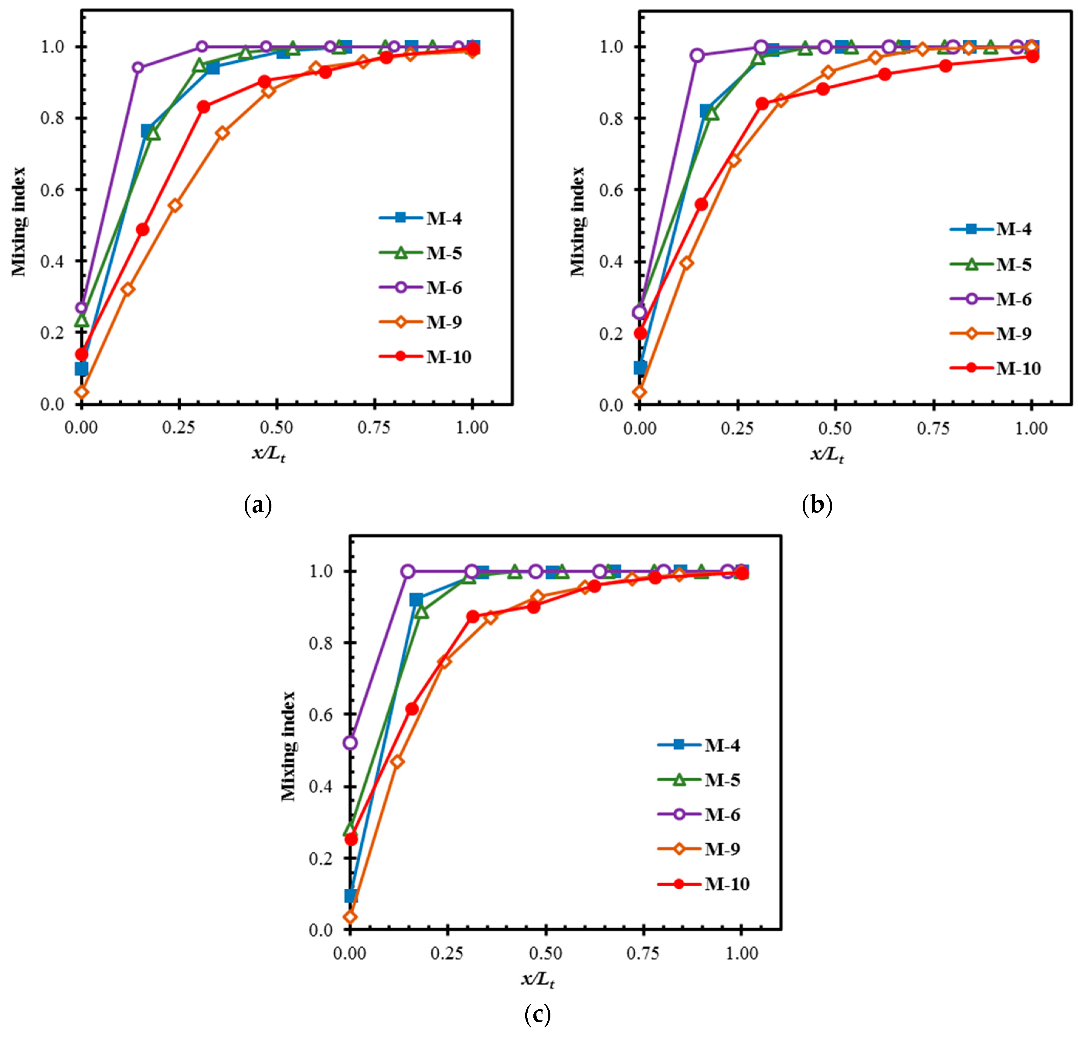
4.2.3. Mixing at High Reynolds Numbers (Re > 40)

At high Reynolds numbers, transverse flows (Dean vortices or secondary flow) become stronger, and mixing is established at a faster rate by stretching and folding of the interfacial area. Increasing the inertial force of the fluids is one of the easiest ways to enhance mixing at high-Re range. At the highest Reynolds number (Re = 120), almost all the micromixers except M-8 show excellent mixing performance. And, M-4, M-5, and M-6 attain almost complete mixing in the whole high-Re range.
The quantitative comparison in Table 4 demonstrates that even simple 2D serpentine micromixers (M-1 and M-2) show more than 97% mixing at Re = 60, and more than 99% mixing at Re = 80 and 120. M-3 having asymmetrical SAR structure reaches a mixing index of 0.89 at Re = 120. From Table 5, it is observed that M-1 and M-2 show 7.1% and 20.6% reduction in pressure than those of M-4 at Re = 80 and 120, respectively. Hence, M-4 shows 7.4% and 20.5% lower MC values than those of M-2 at Re = 80 and 120, respectively, in Table 6. However, it shows 11.6% higher MC than that of M-2 at Re = 60. M-3 shows the highest MC values among the 2-D micromixers due to the lowest pressure drops.
The 3D micromixer M-7 also reaches a mixing index over 0.9 at Re = 80. There are minimal variations among the mixing indices of the 3D micromixers in this Re range if M-7 and M-8 are excepted. However, M-5 and M-6 achieve complete mixing at the expense of a high pressure drops. M5 and M-6 show approximately 7.5 times and 168 times higher pressure drops, respectively, as compared to M-10 at Re = 60. Hence, M-10 shows approximately 7.5 times higher MC as compared to M-5 in this Re range. The worst mixing performance among the tested micromixers is obtained by M-8.
Figure 14 shows the developments of mixing in M-4, M-5, M-6, M-9, and M-10 at different Reynolds numbers. The rates of development of mixing near the inlets of M-4, M-5, and M-6 are found to be higher than those of M-9 and M-10 in this Re range. M-4 shows the highest development rate, and M-5, and M-6 show almost the same developments of mixing in the whole high-Re range (Re = 60, 80, and 120). As Reynolds number increases, the development rates of these three micromixers generally increase. M-4 achieves almost complete mixing within 15–30% of the length, and M-5 and M-6 achieve it within 30–50% of the length in this Re range. We found that 50% of the length of M-5 and M-6 where complete mixing is achieved, still show approximately 3 times and 84 times higher pressure drops, respectively, compared to M-10 at Re = 60. M-10 shows approximately 3.4 times higher MC as compared to 50%-length of M-5 at this Reynolds number. M-10 shows slightly better mixing rate than M-9 at Re = 60. M-9 and M-10 show similar trends of the mixing development especially at Re = Re–120, where the mixing improves continuously until the exit is approached.

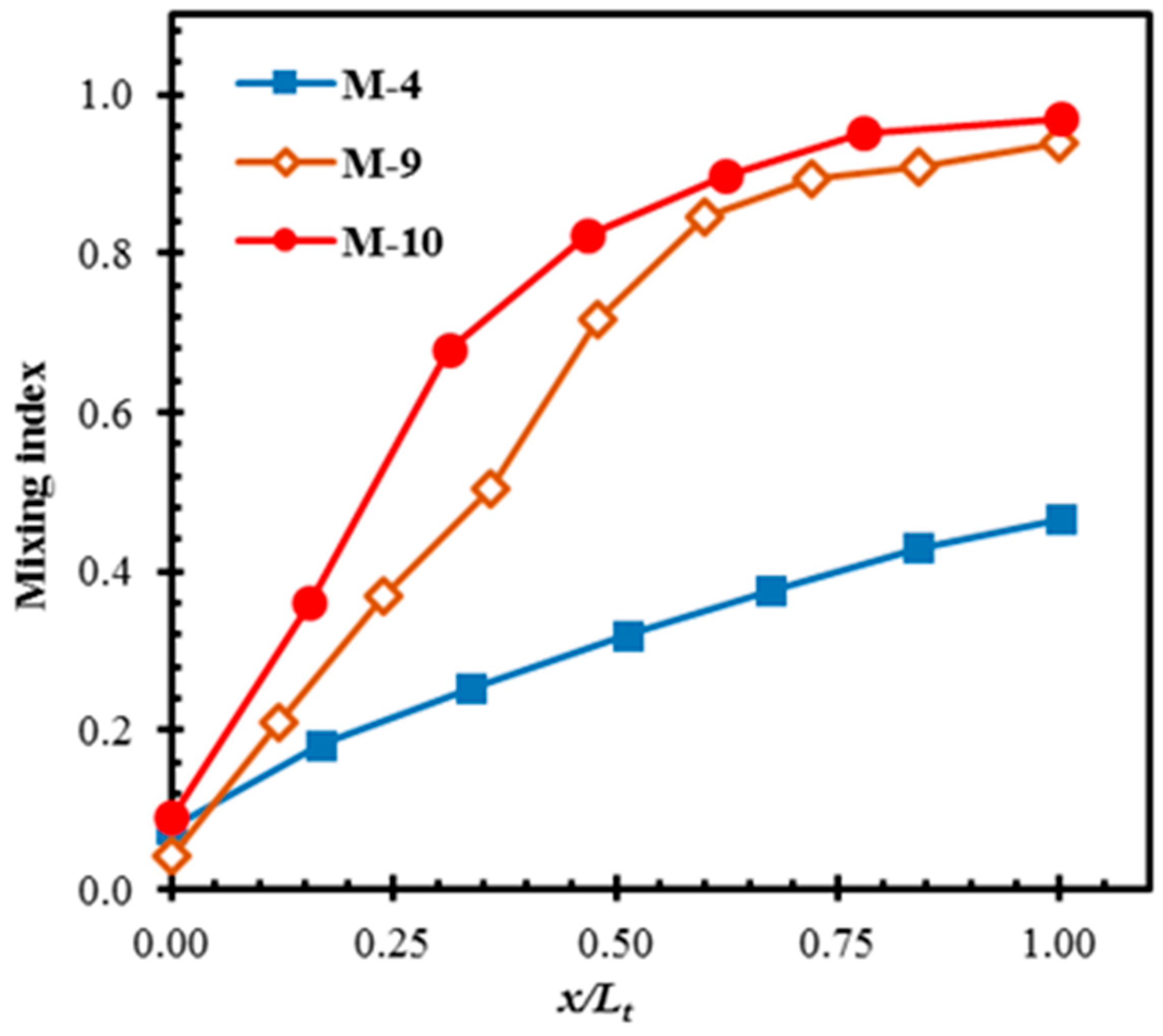
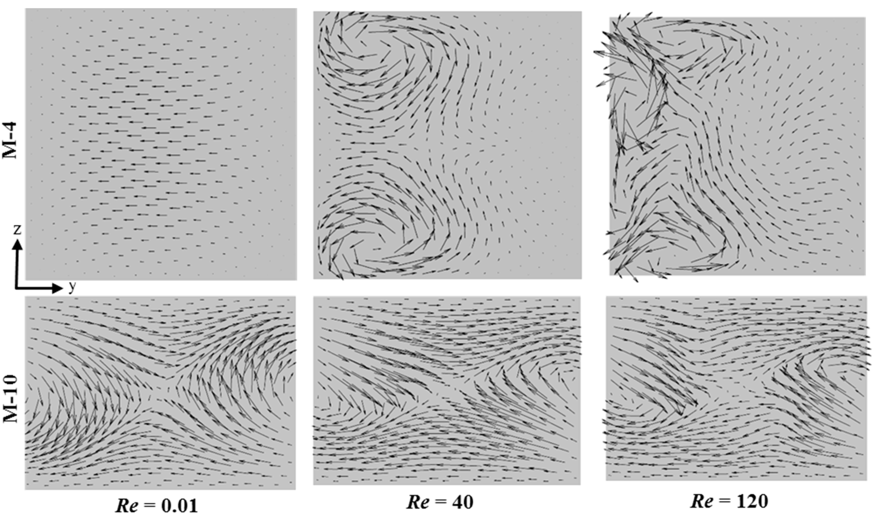
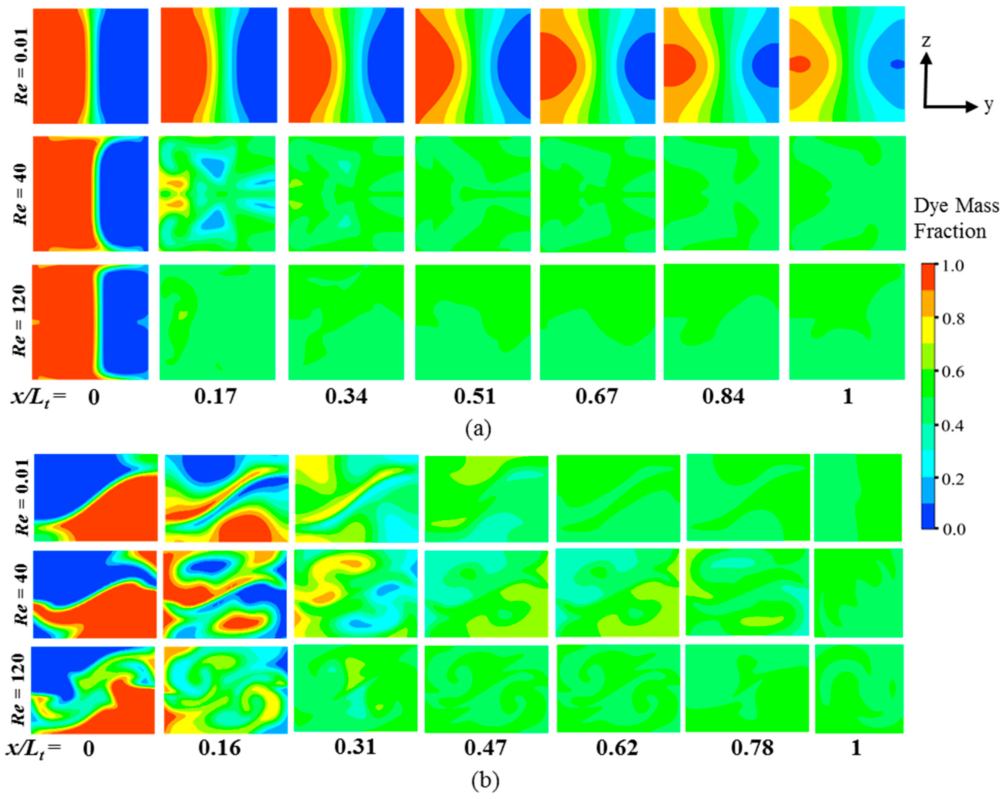
4.2.4. Comparison of Velocity and Concentration Fields between M-4 and M-10

For M-4 and M-10, which show the best mixing performances among the 2D and 3D micromixers, respectively, flow structures and concentration distributions were compared at different Reynolds numbers. Figure 15 shows the flow structures on a y-z plane at x/Lt = 0.16 (plane A2 marked in Figure 4 and Figure 10) for different Reynolds numbers. At Re = 0.01, M-4 shows the flow moving parallel to the wall, and there is no flow disturbance. However, at Re = 40, two symmetrical counter-rotating vortices are seen. These vortices get stronger with the increase in Reynolds number, as shown at Re = 120 with the additional vortices. Contrarily, velocity vectors in M-10 show a saddle-shaped flow structure even at the lowest Reynold number (Re = 0.01). This is the reason for the high mixing performance of M-10 in the low-Re range, which is discussed in Section 4.2.1. This result is in line with the observation in previous studies [84,87] that the saddle-shaped flow structure enhances mixing by stretching and folding of the fluid interfaces.
Figure 16 shows the dye concentrations on y-z planes of M-4 and M-10 for different Reynolds numbers. The progress of homogenization of the concentration in M-4 is much slower than that in M-10 at Re = 0.01. As shown in Figure 15, the fluids are mixed by pure diffusion in M-4, while M-10 shows a strong secondary flow structure even at this low Reynolds number, which is effective in promoting mixing. However, at high Reynolds numbers, the progress of mixing in M-4 is much faster than that in M-10 due to the occurrence of flow disturbances in the form of vortices (Figure 15) and high-inertia collisions of the streams on their recombinations as discussed in [77].
A selection procedure for micromixers is suggested as follows. Once the Reynolds number is fixed depending on the application, the micromixers showing preferred mixing index level should be selected considering ease of fabrication (2D or 3D). Pressure drop should also be considered as a vital factor in the case where the deformation of a sample will impact the outcome of the process, such as in biological applications. After narrowing down the micromixer types, mixing cost should be checked for the final selection.

5. Conclusions

Ten typical micromixers representing five different mixing mechanisms were analyzed quantitatively using Navier-Stokes equations under same working fluids, flow conditions, and axial channel length across a wide range of Reynolds number (Re = 0.01–120). In the results, M-9 and M-10 showed the best overall mixing indices among all the tested micromixers over the entire range of Re, while M-4 showed the best overall mixing indices among the 2D micromixers. However, M-3 showed the best overall MC values among the 2-D micromixers due to its incredibly low pressure drop regardless of Reynolds number. Compared to M-9 and M-10, M-4 showed far lower mixing indices in the low-Re range, but was represented among the similar or better mixing indices in the intermediate- and high-Re ranges. M-9 showed lower mixing performance than M-10 in the low-Re range, but showed higher mixing indices in the intermediate-Re range. M-10 showed the best overall MC values among the tested micromixers, which were slightly higher than those of M-9. The worst mixing performance was obtained by M-3 in the low-Re range, but by M-8 in the high-Re range. The stretching and folding of the fluid streams around the hyperbolic points created by the saddle-shaped flow structure in the crossing channel are more effective for mixing as compared to those generated by the grooves and barriers. Furthermore, the chaotic advection by crossing channels is generated over the entire range of Reynolds numbers, while for the other 2D and 3D channel designs, it is observed only at higher Reynolds numbers. In the crossing-channel micromixers, mixing does not depend upon inertial force, as indicated by good mixing even at low Reynolds numbers. Hence, these micromixers can also be applied to mix fluids having high viscosity.
Therefore, among the tested micromixers, the Tesla structure micromixer (M-4) is recommended in the intermediate- and high-Re ranges considering high mixing performance and easy fabrication due to the planar structure, unless pressure drop is critical. The 3D micromixers, M-9 and M-10 are recommended in the low-Re range considering their excellent mixing performance. But, the fabrication of their two-layer structures with the traditional photolithography process is a challenging task due to the misalignment issue of the top and bottom layers. The results of this comparative analysis are intended to provide guidance for the selection of effective micromixers under different flow conditions in various microfluidic applications.

Author Contributions

Conceptualization, W.R., S.H., and K.-Y.K.; numerical simulation, W.R. and S.H.; formal analysis, W.R.; investigation, W.R.; resources, K.-Y.K.; data curation, W.R.; writing—original draft preparation, W.R., S.H.; writing—review and editing, W.R. and K.-Y.K.; supervision, K.-Y.K.; project administration, W.R., S.H., and K.-Y.K.; funding acquisition, K.-Y.K. All authors have read and agreed to the published version of the manuscript.

Funding

This work was supported by the National Research Foundation of Korea (NRF) grant funded by the Korean government (MSIT) (No. 2019R1A2C1007657).

Conflicts of Interest

The authors declare there is no conflict of interest.

Nomenclature

cmass fraction
Ddiffusion coefficient (m2/s)
Lilength of initial part of main channel (µm)
Leexit channel length (µm)
Lttotal length of the micromixer (µm)
Mmixing index
M0mixing index at the exit
Nnumber of sampling points
Ppressure drop (Pa)
Pipitch length (µm)
ReReynolds number
SAR
U
split and recombine
average inlet velocity (m/s)
Wwidth of main channel (µm)
x, y, zCartesian coordinates
Greek Symbols
µfluid dynamic viscosity (kg·m−1·s−1)
νfluid Kinematic viscosity (m2/s)
ρfluid density (kg/m3)
σstandard deviation
Subscripts
isampling point or fluid component
moptimal mixing
maxmaximum value
xaxial distance

References

  1. Park, T.; Lee, S.; Seong, G.H.; Choo, J.; Lee, E.K.; Kim, Y.S.; Ji, W.H.; Hwang, S.Y.; Gweon, D.G.; Lee, S. Highly sensitive signal detection of duplex dye-labelled DNA oligonucleotides in a PDMS microfluidic chip: Confocal surface-enhanced Raman spectroscopic study. Lab Chip 2005, 5, 437–442. [Google Scholar] [CrossRef]
  2. Rapp, B.E.; Gruhl, F.J.; Länge, K. Biosensors with label-free detection designed for diagnostic applications. Anal. Bioanal. Chem. 2010, 398, 2403–2412. [Google Scholar] [CrossRef]
  3. Rahman, M.; Rebrov, E. Microreactors for gold nanoparticles synthesis: From faraday to flow. Processes 2014, 2, 466–493. [Google Scholar] [CrossRef] [Green Version]
  4. Stone, H.A.; Stroock, A.D.; Ajdari, A. Engineering flows in small devices. Annu. Rev. Fluid Mech. 2004, 36, 381–411. [Google Scholar] [CrossRef] [Green Version]
  5. Squires, T.M.; Quake, S.R. Microfluidics: Fluid physics at the nanoliter scale. Rev. Mod. Phys. 2005, 77, 977–1026. [Google Scholar] [CrossRef] [Green Version]
  6. Hessel, V.; Löwe, H.; Schönfeld, F. Micromixers—A review on passive and active mixing principles. Chem. Eng. Sci. 2005, 60, 2479–2501. [Google Scholar] [CrossRef]
  7. Nguyen, N.T. Micromixers: Fundamentals, Design and Fabrication; William Andrew Publishers: New York, NY, USA, 2011. [Google Scholar]
  8. Ingham, C.J.; van Hylckama Vlieg, J.E.T. MEMS and the microbe. Lab Chip 2008, 8, 1604–1616. [Google Scholar] [CrossRef] [PubMed]
  9. Schulte, T.H.; Bardell, R.L.; Weigl, B.H. Microfluidic technologies in clinical diagnostics. Clin. Chim. Acta 2002, 321, 1–10. [Google Scholar] [CrossRef]
  10. Razzacki, S.Z.; Thwar, P.K.; Yang, M.; Ugaz, V.M.; Burns, M.A. Integrated microsystems for controlled drug delivery. Adv. Drug Deliv. Rev. 2004, 56, 185–198. [Google Scholar] [CrossRef] [PubMed]
  11. Yang, A.S.; Chuang, F.C.; Chen, C.K.; Lee, M.H.; Chen, S.W.; Su, T.L.; Yang, Y.C. A high-performance micromixer using three-dimensional Tesla structures for bio-applications. Chem. Eng. J. 2015, 263, 444–451. [Google Scholar] [CrossRef]
  12. Liu, R.H.; Lenigk, R.; Druyor-Sanchez, R.L.; Yang, J.; Grodzinski, P. Hybridization enhancement using cavitation microstreaming. Anal. Chem. 2003, 75, 1911–1917. [Google Scholar] [CrossRef] [PubMed]
  13. Chen, Q.; Wu, J.; Zhang, Y.; Lin, J.M. Qualitative and quantitative analysis of tumor cell metabolism via stable isotope labeling assisted microfluidic chip electrospray ionization mass spectrometry. Anal. Chem. 2012, 84, 1695–1701. [Google Scholar] [CrossRef] [PubMed]
  14. Westerhausen, C.; Schnitzler, L.G.; Wendel, D.; Krzysztoń, R.; Lächelt, U.; Wagner, E.; Rädler, J.O.; Wixforth, A. Controllable acoustic mixing of fluids in microchannels for the fabrication of therapeutic nanoparticles. Micromachines 2016, 7, 150. [Google Scholar] [CrossRef] [PubMed] [Green Version]
  15. Huang, P.H.; Zhao, S.; Bachman, H.; Nama, N.; Li, Z.; Chen, C.; Yang, S.; Wu, M.; Zhang, S.P.; Huang, T.J. Acoustofluidic synthesis of particulate nanomaterials. Adv. Sci. 2019, 6, 1900913. [Google Scholar] [CrossRef] [Green Version]
  16. Culbertson, C.T.; Mickleburgh, T.G.; Stewart-James, S.A.; Sellens, K.A.; Pressnall, M. Micro total analysis systems: Fundamental advances and biological applications. Anal. Chem. 2014, 86, 95–118. [Google Scholar] [CrossRef] [PubMed] [Green Version]
  17. Bouvier, E.S.P.; Koza, S.M. Advances in size-exclusion separations of proteins and polymers by UHPLC. TrAC Trends Anal. Chem. 2014, 63, 85–94. [Google Scholar] [CrossRef] [Green Version]
  18. Bachman, H.; Huang, P.H.; Zhao, S.; Yang, S.; Zhang, P.; Fu, H.; Huang, T.J. Acoustofluidic devices controlled by cell phones. Lab Chip 2018, 18, 433–441. [Google Scholar] [CrossRef]
  19. Nama, N.; Huang, P.H.; Huang, T.J.; Costanzo, F. Investigation of micromixing by acoustically oscillated sharp-edges. Biomicrofluidics 2016, 10, 024124. [Google Scholar] [CrossRef]
  20. Huang, P.H.; Chan, C.Y.; Li, P.; Nama, N.; Xie, Y.; Wei, C.H.; Chen, Y.; Ahmed, D.; Huang, T.J. A spatiotemporally controllable chemical gradient generator via acoustically oscillating sharp-edge structures. Lab Chip 2015, 15, 4166–4176. [Google Scholar] [CrossRef] [Green Version]
  21. Huang, P.H.; Chan, C.Y.; Li, P.; Wang, Y.; Nama, N.; Bachman, H.; Huang, T.J. A sharp-edge-based acoustofluidic chemical signal generator. Lab Chip 2018, 18, 1411–1421. [Google Scholar] [CrossRef]
  22. Harnett, C.K.; Templeton, J.; Dunphy-Guzman, K.A.; Senousy, Y.M.; Kanouff, M.P. Model based design of a microfluidic mixer driven by induced charge electroosmosis. Lab Chip 2008, 8, 565–572. [Google Scholar] [CrossRef] [PubMed]
  23. Ahmed, D.; Mao, X.; Shi, J.; Juluri, B.K.; Huang, T.J. A millisecond micromixer via single-bubble-based acoustic streaming. Lab Chip 2009, 9, 2738. [Google Scholar] [CrossRef]
  24. Nguyen, N.T.; Wu, Z. Micromixers—A review. J. Micromech. Microeng. 2005, 15, R1–R16. [Google Scholar] [CrossRef]
  25. Ebadi, M.; Moshksayan, K.; Kashaninejad, N.; Saidi, M.S.; Nguyen, N.T. A tool for designing tree-like concentration gradient generators for lab-on-a-chip applications. Chem. Eng. Sci. 2020, 212, 115339. [Google Scholar] [CrossRef]
  26. Rismanian, M.; Saidi, M.S.; Kashaninejad, N. A new non-dimensional parameter to obtain the minimum mixing length in tree-like concentration gradient generators. Chem. Eng. Sci. 2019, 195, 120–126. [Google Scholar] [CrossRef]
  27. Aref, H. Stirring by chaotic advection. J. Fluid Mech. 1984, 143, 1–21. [Google Scholar] [CrossRef]
  28. Ottino, J.M. The Kinematics of Mixing: Stretching, Chaos, and Transport; Cambridge Texts in Applied Mathematics; Cambridge University Press: Cambridge, Oxford, UK, 1989. [Google Scholar]
  29. Stroock, A.D.; Dertinger, S.K.W.; Ajdari, A.; Mezic, I.; Stone, H.A.; Whitesides, G.M. Chaotic mixer for microchannels. Science 2002, 295, 647–651. [Google Scholar] [CrossRef] [Green Version]
  30. Fu, L.M.; Fang, W.C.; Hou, H.H.; Wang, Y.N.; Hong, T.F. Rapid vortex microfluidic mixer utilizing double-heart chamber. Chem. Eng. J. 2014, 249, 246–251. [Google Scholar] [CrossRef]
  31. Swickrath, M.J.; Burns, S.D.; Wnek, G.E. Modulating passive micromixing in 2-D microfluidic devices via discontinuities in surface energy. Sens. Actuators B Chem. 2009, 140, 656–662. [Google Scholar] [CrossRef]
  32. Mengeaud, V.; Josserand, J.; Girault, H.H. Mixing processes in a zigzag microchannel: Finite element simulations and optical study. Anal. Chem. 2002, 74, 4279–4286. [Google Scholar] [CrossRef]
  33. Wang, W.; Zhao, S.; Shao, T.; Jin, Y.; Cheng, Y. Visualization of micro-scale mixing in miscible liquids using? LIF technique and drug nano-particle preparation in T-shaped micro-channels. Chem. Eng. J. 2012, 192, 252–261. [Google Scholar] [CrossRef]
  34. Roudgar, M.; Brunazzi, E.; Galletti, C.; Mauri, R. Numerical study of split T-micromixers. Chem. Eng. Technol. 2012, 35, 1291–1299. [Google Scholar] [CrossRef]
  35. Hsieh, S.S.; Lin, J.W.; Chen, J.H. Mixing efficiency of Y-type micromixers with different angles. Int. J. Heat Fluid Flow 2013, 44, 130–139. [Google Scholar] [CrossRef]
  36. Hengzi, W.; Pio, I.; Erol, H.; Syed, M.; Wang, H.; Iovenitti, P.; Harvey, E.; Masood, S. Optimizing layout of obstacles for enhanced mixing in microchannels. Smart Mater. Struct. 2002, 11, 662. [Google Scholar]
  37. Ait Mouheb, N.; Malsch, D.; Montillet, A.; Solliec, C.; Henkel, T. Numerical and experimental investigations of mixing in T-shaped and cross-shaped micromixers. Chem. Eng. Sci. 2012, 68, 278–289. [Google Scholar] [CrossRef]
  38. Wang, L.; Liu, D.; Wang, X.; Han, X. Mixing enhancement of novel passive microfluidic mixers with cylindrical grooves. Chem. Eng. Sci. 2012, 81, 157–163. [Google Scholar] [CrossRef]
  39. Vanka, S.P.; Luo, G.; Winkler, C.M. Numerical study of scalar mixing in curved channels at low Reynolds numbers. AIChE J. 2004, 50, 2359–2368. [Google Scholar] [CrossRef]
  40. Hossain, S.; Ansari, M.A.; Kim, K.Y. Evaluation of the mixing performance of three passive micromixers. Chem. Eng. J. 2009, 150, 492–501. [Google Scholar] [CrossRef]
  41. Alam, A.; Kim, K.Y. Analysis of mixing in a curved microchannel with rectangular grooves. Chem. Eng. J. 2012, 181–182, 708–716. [Google Scholar] [CrossRef]
  42. Liu, R.H.; Stremler, M.A.; Sharp, K.V.; Olsen, M.G.; Santiago, J.G.; Adrian, R.J.; Aref, H.; Beebe, D.J. Passive mixing in a three-dimensional serpentine microchannel. J. Microelectromechan. Syst. 2000, 9, 190–197. [Google Scholar] [CrossRef]
  43. Beebe, D.J.; Adrian, R.J.; Olsen, M.G.; Stremler, M.A.; Aref, H.; Jo, B.H. Passive mixing in microchannels: Fabrication and flow experiments. Mecaniqe Ind. 2001, 2, 343–348. [Google Scholar] [CrossRef]
  44. Liu, Y.Z.; Kim, B.J.; Sung, H.J. Two-fluid mixing in a microchannel. Int. J. Heat Fluid Flow 2004, 25, 986–995. [Google Scholar] [CrossRef]
  45. Ansari, M.A.; Kim, K.Y. Parametric study on mixing of two fluids in a three-dimensional serpentine microchannel. Chem. Eng. J. 2009, 146, 439–448. [Google Scholar] [CrossRef]
  46. Lee, K.; Kim, C.; Shin, K.S.; Lee, J.W.; Ju, B.K.; Kim, T.S.; Lee, S.K.; Kang, J.Y. Fabrication of round channels using the surface tension of PDMS and its application to a 3D serpentine mixer. J. Micromech. Microeng. 2007, 17, 1533–1541. [Google Scholar] [CrossRef]
  47. Lin, Y. Numerical characterization of simple three-dimensional chaotic micromixers. Chem. Eng. J. 2015, 277, 303–311. [Google Scholar] [CrossRef]
  48. Lin, Y.; Yu, X.; Wang, Z.; Tu, S.T.; Wang, Z. Design and evaluation of an easily fabricated micromixer with three-dimensional periodic perturbation. Chem. Eng. J. 2011, 171, 291–300. [Google Scholar] [CrossRef]
  49. Park, J.M.; Kwon, T.H. Numerical characterization of three-dimensional serpentine micromixers. AIChE J. 2008, 54, 1999–2008. [Google Scholar] [CrossRef]
  50. Cortes-Quiroz, C.A.; Azarbadegan, A.; Zangeneh, M.; Goto, A. Analysis and multi-criteria design optimization of geometric characteristics of grooved micromixer. Chem. Eng. J. 2010, 160, 852–864. [Google Scholar] [CrossRef]
  51. Du, Y.; Zhang, Z.; Yim, C.; Lin, M.; Cao, X. Evaluation of floor-grooved micromixers using concentration-channel length profiles. Micromachines 2010, 1, 19–33. [Google Scholar] [CrossRef] [Green Version]
  52. Tóth, E.L.; Holczer, E.G.; Iván, K.; Fürjes, P. Optimized simulation and validation of particle advection in asymmetric staggered herringbone type micromixers. Micromachines 2015, 6, 136–150. [Google Scholar] [CrossRef] [Green Version]
  53. Sarkar, A.; Narváez, A.; Harting, J. Quantification of the performance of chaotic micromixers on the basis of finite time Lyapunov exponents. Microfluid. Nanofluidics 2012, 13, 19–27. [Google Scholar] [CrossRef] [Green Version]
  54. Hossain, S.; Husain, A.; Kim, K.Y. Shape optimization of a micromixer with staggered-herringbone grooves patterned on opposite walls. Chem. Eng. J. 2010, 162, 730–737. [Google Scholar] [CrossRef]
  55. Afzal, A.; Kim, K.Y. Three-objective optimization of a staggered herringbone micromixer. Sens. Actuators B Chem. 2014, 192, 350–360. [Google Scholar] [CrossRef]
  56. Lin, D.; He, F.; Liao, Y.; Lin, J.; Liu, C.; Song, J.; Cheng, Y. Three-dimensional staggered herringbone mixer fabricated by femtosecond laser direct writing. J. Opt. 2013, 15, 025601. [Google Scholar] [CrossRef]
  57. Ansari, M.A.; Kim, K.Y. Shape optimization of a micromixer with staggered herringbone groove. Chem. Eng. Sci. 2007, 62, 6687–6695. [Google Scholar] [CrossRef]
  58. Kim, D.S.; Lee, S.W.; Kwon, T.H.; Lee, S.S. A barrier embedded chaotic micromixer. J. Micromech. Microeng. 2004, 14, 798–805. [Google Scholar] [CrossRef]
  59. Hossain, S.; Kim, K.Y. Mixing analysis in a three-dimensional serpentine split-and-recombine micromixer. Chem. Eng. Res. Des. 2015, 100, 95–103. [Google Scholar] [CrossRef]
  60. Ohkawa, K.; Nakamoto, T.; Izuka, Y.; Hirata, Y.; Inoue, Y. Flow and mixing characteristics of? Type plate static mixer with splitting and inverse recombination. Chem. Eng. Res. Des. 2008, 86, 1447–1453. [Google Scholar] [CrossRef]
  61. Lee, S.W.; Lee, S.S. Rotation effect in split and recombination micromixing. Sens. Actuators B Chem. 2008, 129, 364–371. [Google Scholar] [CrossRef]
  62. Hardt, S.; Pennemann, H.; Schönfeld, F. Theoretical and experimental characterization of a low-Reynolds number split-and-recombine mixer. Microfluid. Nanofluidics 2006, 2, 237–248. [Google Scholar] [CrossRef]
  63. Lee, S.W.; Kim, D.S.; Lee, S.S.; Kwon, T.H. A split and recombination micromixer fabricated in a PDMS three-dimensional structure. J. Micromech. Microeng. 2006, 16, 1067–1072. [Google Scholar] [CrossRef]
  64. Viktorov, V.; Nimafar, M. A novel generation of 3D SAR-based passive micromixer: Efficient mixing and low pressure drop at a low Reynolds number. J. Micromech. Microeng. 2013, 23, 055023. [Google Scholar] [CrossRef]
  65. Nimafar, M.; Viktorov, V.; Martinelli, M. Experimental comparative mixing performance of passive micromixers with H-shaped sub-channels. Chem. Eng. Sci. 2012, 76, 37–44. [Google Scholar] [CrossRef]
  66. Nimafar, M.; Viktorov, V.; Martinelli, M. Experimental investigation of split and recombination micromixer in confront with basic T- and O- type micromixers. Int. J. Mech. Appl. 2012, 2, 61–69. [Google Scholar] [CrossRef]
  67. Carrier, O.; Funfschilling, D.; Debas, H.; Poncin, S.; Löb, P.; Li, H.Z. Pressure drop in a split-and-recombine caterpillar micromixer in case of newtonian and non-newtonian fluids. AIChE J. 2013, 59, 2679–2685. [Google Scholar] [CrossRef]
  68. Li, J.; Xia, G.; Li, Y. Numerical and experimental analyses of planar asymmetric split-and-recombine micromixer with dislocation sub-channels. J. Chem. Technol. Biotechnol. 2013, 88, 1757–1765. [Google Scholar] [CrossRef]
  69. Ansari, M.A.; Kim, K.Y. Mixing performance of unbalanced split and recombine micomixers with circular and rhombic sub-channels. Chem. Eng. J. 2010, 162, 760–767. [Google Scholar] [CrossRef]
  70. Xia, G.; Li, J.; Tian, X.; Zhou, M. Analysis of flow and mixing characteristics of planar asymmetric split-and-recombine (P-SAR) micromixers with fan-shaped cavities. Ind. Eng. Chem. Res. 2012, 51, 7816–7827. [Google Scholar] [CrossRef]
  71. Pennella, F.; Rossi, M.; Ripandelli, S.; Rasponi, M.; Mastrangelo, F.; Deriu, M.A.; Ridolfi, L.; Kähler, C.J.; Morbiducci, U. Numerical and experimental characterization of a novel modular passive micromixer. Biomed. Microdevices 2012, 14, 849–862. [Google Scholar] [CrossRef] [Green Version]
  72. Hong, C.C.; Choi, J.W.; Ahn, C.H. A novel in-plane passive microfluidic mixer with modified Tesla structures. Lab Chip 2004, 4, 109–113. [Google Scholar] [CrossRef]
  73. Chung, C.K.; Chang, C.K.; Lai, C.C. Simulation and fabrication of a branch-channel rhombic micromixer for low pressure drop and short mixing length. Microsyst. Technol. 2014, 20, 1981–1986. [Google Scholar] [CrossRef]
  74. Xia, G.D.; Li, Y.F.; Wang, J.; Zhai, Y.L. Numerical and experimental analyses of planar micromixer with gaps and baffles based on field synergy principle. Int. Commun. Heat Mass Transf. 2016, 71, 188–196. [Google Scholar] [CrossRef]
  75. Hossain, S.; Kim, K.Y. Mixing analysis of passive micromixer with unbalanced three-split rhombic sub-channels. Micromachines 2014, 5, 913–928. [Google Scholar] [CrossRef]
  76. Ansari, M.A.; Kim, K.Y.; Anwar, K.; Kim, S.M. A novel passive micromixer based on unbalanced splits and collisions of fluid streams. J. Micromech. Microeng. 2010, 20, 055007. [Google Scholar] [CrossRef] [Green Version]
  77. Hossain, S.; Ansari, M.A.; Husain, A.; Kim, K.Y. Analysis and optimization of a micromixer with a modified Tesla structure. Chem. Eng. J. 2010, 158, 305–314. [Google Scholar] [CrossRef]
  78. Sheu, T.S.; Chen, S.J.; Chen, J.J. Mixing of a split and recombine micromixer with tapered curved microchannels. Chem. Eng. Sci. 2012, 71, 321–332. [Google Scholar] [CrossRef]
  79. Afzal, A.; Kim, K.Y. Passive split and recombination micromixer with convergent-divergent walls. Chem. Eng. J. 2012, 203, 182–192. [Google Scholar] [CrossRef]
  80. Kim, D.S.; Lee, S.H.; Kwon, T.H.; Ahn, C.H. A serpentine laminating micromixer combining splitting/recombination and advection. Lab Chip 2005, 5, 739–747. [Google Scholar] [CrossRef] [Green Version]
  81. Park, J.M.; Kim, D.S.; Kang, T.G.; Kwon, T.H. Improved serpentine laminating micromixer with enhanced local advection. Microfluid. Nanofluidics 2008, 4, 513–523. [Google Scholar] [CrossRef]
  82. Feng, X.; Ren, Y.; Jiang, H. An effective splitting-and-recombination micromixer with self-rotated contact surface for wide Reynolds number range applications. Biomicrofluidics 2013, 7, 1–10. [Google Scholar] [CrossRef] [Green Version]
  83. Lim, T.W.; Son, Y.; Jeong, Y.J.; Yang, D.Y.; Kong, H.J.; Lee, K.S.; Kim, D.P. Three-dimensionally crossing manifold micro-mixer for fast mixing in a short channel length. Lab Chip 2011, 11, 100–103. [Google Scholar] [CrossRef] [PubMed] [Green Version]
  84. Xia, H.M.; Wan, S.Y.M.; Shu, C.; Chew, Y.T. Chaotic micromixers using two-layer crossing channels to exhibit fast mixing at low Reynolds numbers. Lab Chip 2005, 5, 748–755. [Google Scholar] [CrossRef] [PubMed]
  85. Li, L.; Chen, Q.D.; Tsai, C.T. Three dimensional triangle chaotic micromixer. Adv. Mater. Res. 2014, 875–877, 1189–1193. [Google Scholar] [CrossRef]
  86. Fang, W.F.; Yang, J.T. A novel microreactor with 3D rotating flow to boost fluid reaction and mixing of viscous fluids. Sens. Actuators B Chem. 2009, 140, 629–642. [Google Scholar] [CrossRef]
  87. Hossain, S.; Lee, I.; Kim, S.M.; Kim, K.Y. A micromixer with two-layer serpentine crossing channels having excellent mixing performance at low Reynolds numbers. Chem. Eng. J. 2017, 327, 268–277. [Google Scholar] [CrossRef]
  88. Raza, W.; Hossain, S.; Kim, K.Y. Effective mixing in a short serpentine split-and-recombination micromixer. Sens. Actuators B Chem. 2018, 258, 381–392. [Google Scholar] [CrossRef]
  89. Hossain, S.; Kim, K.Y. Parametric investigation on mixing in a micromixer with two-layer crossing channels. Springerplus 2016, 5, 794. [Google Scholar] [CrossRef] [Green Version]
  90. Lee, C.Y.; Fu, L.M. Recent advances and applications of micromixers. Sens. Actuators B Chem. 2018, 259, 677–702. [Google Scholar] [CrossRef]
  91. Cai, G.; Xue, L.; Zhang, H.; Lin, J. A review on micromixers. Micromachines 2017, 8, 274. [Google Scholar] [CrossRef]
  92. Jeong, G.S.; Chung, S.; Kim, C.B.; Lee, S.H. Applications of micromixing technology. Analyst 2010, 135, 460–473. [Google Scholar] [CrossRef]
  93. Capretto, L.; Cheng, W.; Hill, M.; Zhang, X. Micromixing within microfluidic devices. Top. Curr. Chem. 2011, 304, 27–68. [Google Scholar] [PubMed]
  94. Lee, C.Y.; Wang, W.T.; Liu, C.C.; Fu, L.M. Passive mixers in microfluidic systems: A review. Chem. Eng. J. 2016, 288, 146–160. [Google Scholar] [CrossRef]
  95. Pennella, F.; Mastrangelo, F.; Gallo, D.; Massai, D.; Deriu, M.A.; Labate, G.F.D.; Bignardi, C.; Montevecchi, F.; Morbiducci, U. A Survey of microchannel geometries for mixing of species in biomicrofluidics. Single Two Phase Flows Chem. Biomed. Eng. 2012, 548–578. [Google Scholar]
  96. Falk, L.; Commenge, J.M. Performance comparison of micromixers. Chem. Eng. Sci. 2010, 65, 405–411. [Google Scholar] [CrossRef]
  97. Viktorov, V.; Mahmud, M.; Visconte, C. Comparative analysis of passive micromixers at a wide range of reynolds numbers. Micromachines 2015, 6, 1166–1179. [Google Scholar] [CrossRef] [Green Version]
  98. Bošković, D.; Loebbecke, S.; Gross, G.A.; Koehler, J.M. Residence time distribution studies in microfluidic mixing structures. Chem. Eng. Technol. 2011, 34, 361–370. [Google Scholar] [CrossRef]
  99. ANSYS. Solver Theory Guide, CFX-15.0; ANSYS Inc.: Canonsburg, PA, USA, 2013. [Google Scholar]
  100. Chung, C.K.; Shih, T.R. A rhombic micromixer with asymmetrical flow for enhancing mixing. J. Micromech. Microeng. 2007, 17, 2495–2504. [Google Scholar] [CrossRef]
Figure 1. Curved micromixer: M-1 (no. of mixing units used: 8). Reproduced with permission from [40].
Micromachines 11 00455 g001
Figure 2. Curved micromixer with rectangular grooves: M-2 (no. of mixing units used: 8). Reproduced with permission from [41].
Micromachines 11 00455 g002
Figure 3. Modified P-SAR micromixer with dislocation sub-channels: M-3 (no. of mixing units used: 4). Reproduced with permission from [68].
Micromachines 11 00455 g003
Figure 4. Modified Tesla micromixer: M-4 (no. of mixing units used: 6). Reproduced with permission from [77].
Micromachines 11 00455 g004
Figure 5. 3D serpentine micromixer: M-5 (no. of mixing units used: 8). Reproduced with permission from [45].
Micromachines 11 00455 g005
Figure 6. 3D serpentine SAR micromixer: M-6 (no. of mixing units used: 18). Reproduced with permission from [59].
Micromachines 11 00455 g006
Figure 7. Improved serpentine lamination micromixer: M-7 (no. of mixing units used: 2) [81].
Micromachines 11 00455 g007
Figure 8. Barrier embedded chaotic micromixer: M-8 (no. of mixing units used: 6) [58].
Micromachines 11 00455 g008
Figure 9. Chaotic micromixer with two-layer crossing microchannels: M-9 (no. of mixing units used: 8). Reproduced with permission from [89].
Micromachines 11 00455 g009
Figure 10. Chaotic micromixer with two-layer serpentine crossing microchannels: M-10 (no. of mixing units used: 6). Reproduced with permission from [87].
Micromachines 11 00455 g010
Figure 11. Variation of the mixing index at the exit with Reynolds number in a curved micromixer [40].
Micromachines 11 00455 g011
Figure 12. Developments of mixing along the length of the micromixers at Re = 0.01.
Micromachines 11 00455 g012
Figure 13. Developments of mixing along the length of the micromixers: (a) Re = 20 and (b) Re = 40.
Micromachines 11 00455 g013
Figure 14. Developments of mixing along the length of the micromixers: (a) Re = 60, (b) Re = 80 and (c) Re = 120.
Micromachines 11 00455 g014
Figure 15. Velocity vectors in M-4 and M-10 at x/Lt = 0.16 (plane A2 in Figure 4 and Figure 10) at different Reynolds numbers.
Micromachines 11 00455 g015
Figure 16. Dye concentration distributions at different Reynolds numbers: (a) M-4; and (b) M-10.
Micromachines 11 00455 g016
Table 1. Types of micromixer designs.
TypeMicromixer DesignMixing MechanismSelected Micromixer
12D designs using serpentine, spiral, curved helical channels [30,31,32,33,34,35,36,37,38,39,40,41]Inertial force (secondary flow, Dean vortex)M-1 [40], M-2 [41]
22D designs with SAR structures [68,69,70,71,72,73,74,75,76,77,78,79]Inertial force, SARM-3 [68], M-4 [77]
33D design with serpentine and/or SAR structures [42,43,44,45,46,47,48,49,59,60,61,62,63,64,65,66,67,80,81]Inertial force, chaotic mixing, multi-laminationM-5 [45], M-6 [59], M-7 [81]
43D design with patterned grooves [29,50,51,52,53,54,55,56,57,58]Inertial force, chaotic mixingM-8 [58]
53D designs with SAR two-layer crossing channels [82,83,84,85,86,87,88,89]Chaotic mixing, multi-laminationM-9 [84], M-10 [87]
Table 2. Selected micromixers.
Micromixer
Designation
MicromixerGeometry (Type in Table 1)Designers [Ref.]Year
M-1Curved micromixer2D serpentine (1)Hossain et al. [40]2009
M-2Curved micromixer with grooves2D serpentine (1)Alam and Kim [41]2012
M-3Modified P-SAR (planar SAR) micromixer with dislocation sub-channels2D SAR (2)Li et al. [68]2013
M-4Modified Tesla micromixer2D SAR (2)Hossain et al. [77]2010
M-53D serpentine micromixer3D serpentine (3)Ansari and Kim [45]2009
M-63D serpentine SAR micromixer3D serpentine SAR (3)Hossain and Kim [59]2015
M-7Improved serpentine laminating micromixer3D serpentine SAR (3)Park et al. [81]2008
M-8Barrier embedded chaotic micromixer3D grooves (4)Kim et al. [58]2004
M-9Chaotic micromixer with two-layer crossing microchannels3D SAR (5)Xia et al. [84]2005
M-10Chaotic micromixer with two-layer serpentine crossing microchannels3D serpentine SAR (5)Hossain et al. [87]2017
Table 3. Optimum numbers of grid nodes selected through grid refinement tests at Re = 40.
MicromixerOptimum Number of MeshesNumber of Finer Meshes% Deviation of Mixing Index between the Optimum and Finest MeshesMicromixerOptimum Number of MeshesNumber of Finer Meshes % Deviation of Mixing Index between the Optimum and Finest Meshes
M-11.81 × 1062.04 × 1061.39M-62.07 × 1062.34 × 1060.10
M-22.07 × 1062.41 × 1061.16M-72.19 × 1062.55 × 1060.54
M-31.55 × 1062.08 × 1060.94M-82.21 × 1062.53 × 1061.05
M-42.16 × 1062.33 × 1060.20M-91.90 × 1062.03 × 1060.10
M-51.79 × 1061.96 × 1060.10M-101.61 × 1061.80 × 1060.11
Table 4. Mixing index at the exit.
MicromixerMixing Index at the Exit
Low-Re RangeIntermediate-Re RangeHigh-Re Range
Re = 0.01Re = 0.1Re = 1Re = 20Re = 40Re = 60Re = 80Re = 120
M-10.5600.2500.2240.5720.7930.9790.9900.998
M-20.5540.2440.2210.6940.8580.9740.9970.997
M-30.2680.1410.1250.2410.4220.6570.8280.890
M-40.4650.2550.2030.8830.9990.9990.9990.999
M-50.5460.3610.3770.9990.9990.9990.9990.999
M-60.6490.5060.4720.9990.9990.9990.9990.999
M-70.9040.5940.5370.5670.7330.8560.9090.963
M-80.3100.2380.2260.2500.2840.3100.3370.401
M-90.9390.9090.9050.9340.9720.9870.9980.996
M-100.9700.9260.9150.9010.9290.9950.9730.996
Table 5. Pressure drop through micromixer.
MicromixerPressure Drop (Pa)
Low-Re RangeIntermediate-Re RangeHigh-Re Range
Re = 0.01Re = 0.1Re = 1Re = 20Re = 40Re = 60Re = 80Re = 120
M-12.95 × 1002.95 × 1012.95 × 1026.77 × 1031.63 × 1042.81 × 1044.18 × 1047.70 × 104
M-22.87 × 1002.87 × 1012.87 × 1026.64 × 1031.62 × 1042.80 × 1044.15 × 1047.68 × 104
M-33.58 × 10−13.72 × 1003.73 × 1018.30 × 1021.95 × 1033.39 × 1035.14 × 1039.72 × 103
M-41.03 × 1001.03 × 1011.04 × 1023.53 × 1031.20 × 1042.58 × 1044.50 × 1049.70 × 104
M-57.94 × 10−17.94 × 1007.96 × 1012.44 × 1037.12 × 1031.39 × 1042.19 × 1044.32 × 104
M-61.67 × 1011.67 × 1021.68 × 1035.32 × 1041.57 × 1053.10 × 1055.15 × 1051.09 × 106
M-72.46 × 1002.46 × 1012.47 × 1025.27 × 1031.16 × 1041.95 × 1042.90 × 1045.49 × 104
M-82.09 × 1002.12 × 1012.12 × 1024.29 × 1038.73 × 1031.33 × 1041.79 × 1042.75 × 104
M-91.78 × 10−11.78 × 1001.78 × 1014.42 × 1021.16 × 1032.21 × 1033.59 × 1037.37 × 103
M-101.63 × 10−11.63 × 1001.63 × 1013.90 × 1029.94 × 1021.84 × 1032.93 × 1035.90 × 103
Table 6. Mixing cost.
MicromixerMixing Cost, MC (Pa−1)
Low-Re RangeIntermediate-Re RangeHigh-Re Range
Re = 0.01Re = 0.1Re = 1Re = 20Re = 40Re = 60Re = 80Re = 120
M-11.90 × 10−18.47 × 10−37.58 × 10−48.45 × 10−54.85 × 10−53.48× 10−52.39 × 10−51.30 × 10−5
M-21.93 × 10−18.48 × 10−37.67 × 10−41.05 × 10−45.29 × 10−53.47× 10−52.40 × 10−51.30 × 10−5
M-37.51 × 10−13.79 × 10−23.36 × 10−32.90 × 10−42.16 × 10−41.94× 10−41.61 × 10−49.15 × 10−5
M-44.50 × 10−12.47 × 10−21.96 × 10−32.50 × 10−48.36 × 10−53.87× 10−52.22 × 10−51.03 × 10−5
M-56.88 × 10−14.55 × 10−24.74 × 10−34.09 × 10−41.40 × 10−47.18× 10−54.57 × 10−52.32 × 10−5
M-63.89 × 10−23.03 × 10−32.82 × 10−41.88 × 10−56.38 × 10−63.22× 10−61.94 × 10−69.20 × 10−7
M-73.67 × 10−12.41 × 10−22.18 × 10−31.07 × 10−46.29 × 10−54.40× 10−53.13 × 10−51.76 × 10−5
M-81.48 × 10−11.12 × 10−21.07 × 10−35.81 × 10−53.25 × 10−52.34× 10−51.88 × 10−51.46 × 10−5
M-95.28 × 1005.11 × 10−15.08 × 10−22.12 × 10−38.38 × 10−44.47× 10−42.78 × 10−41.35 × 10−4
M-105.95 × 1005.68 × 10−15.60 × 10−22.31 × 10−39.34 × 10−45.41× 10−43.32 × 10−41.69 × 10−4

