Bessel Beam: Significance and Applications—A Progressive Review

 ,
,  ,
, 
Abstract
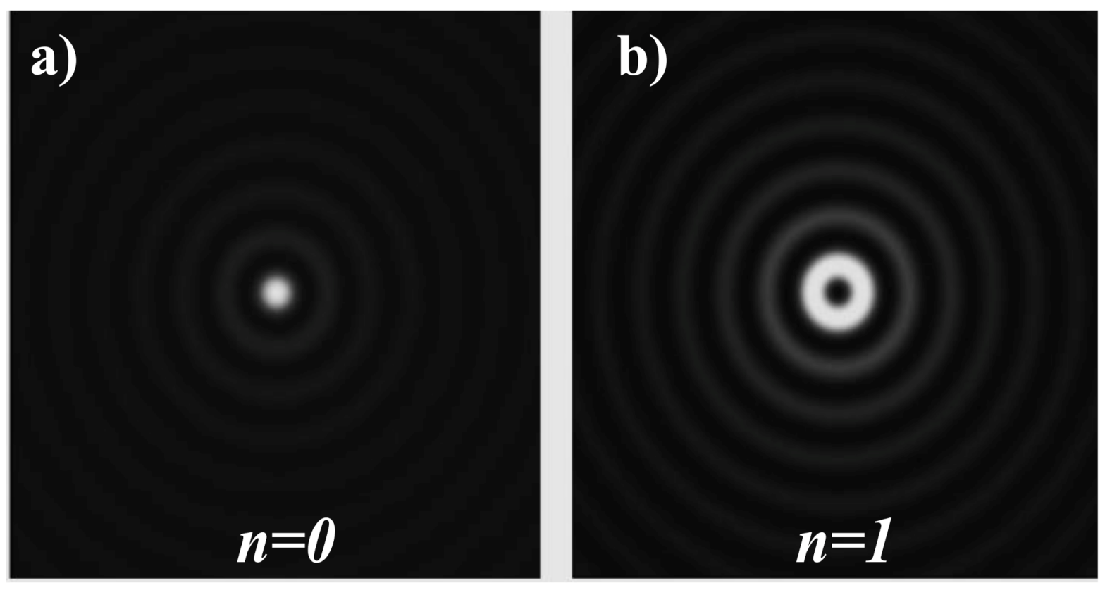
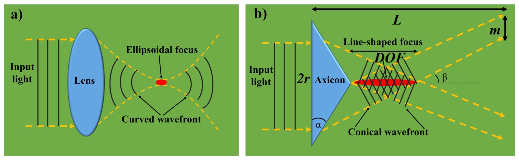
:1. Introduction
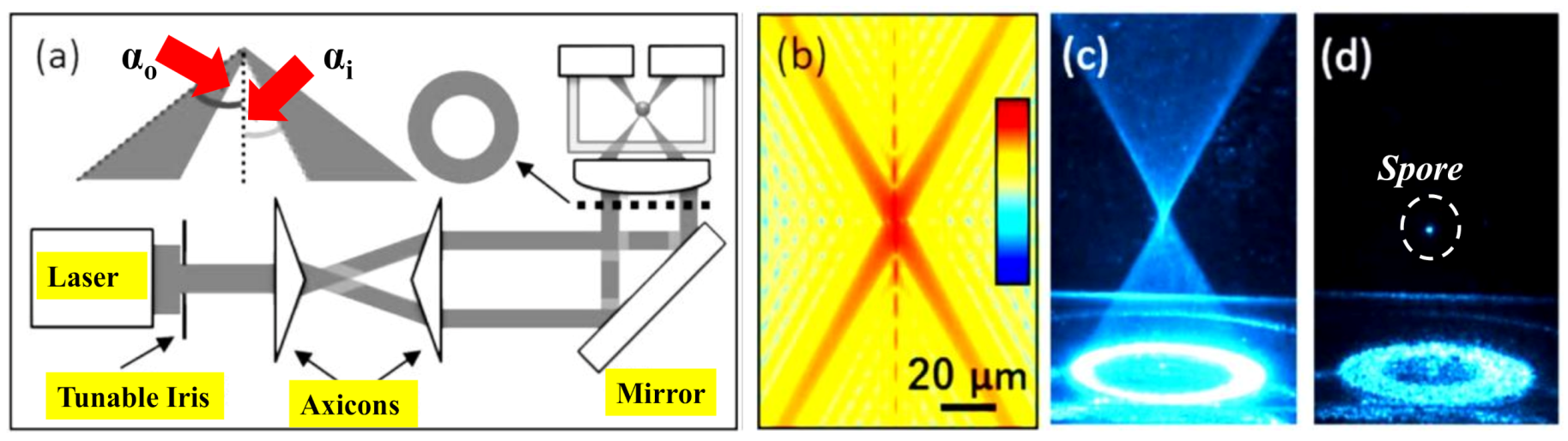
2. Optical Trapping with BBs
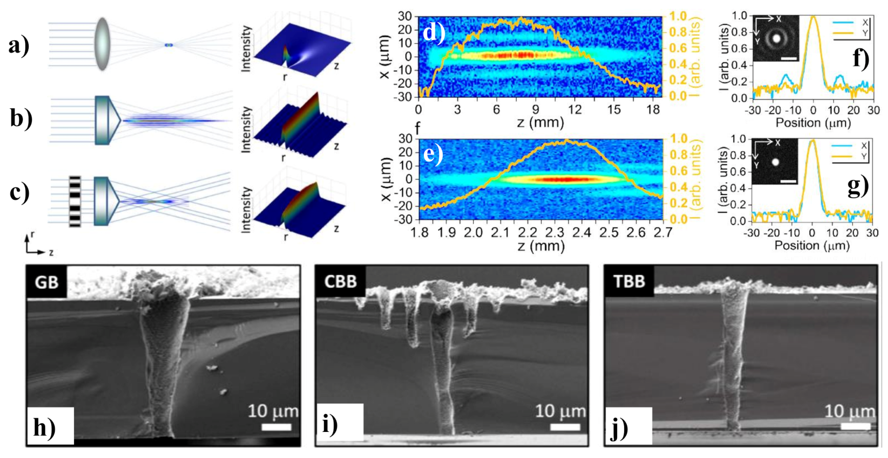
3. Material Processing via Ultrafast BBs
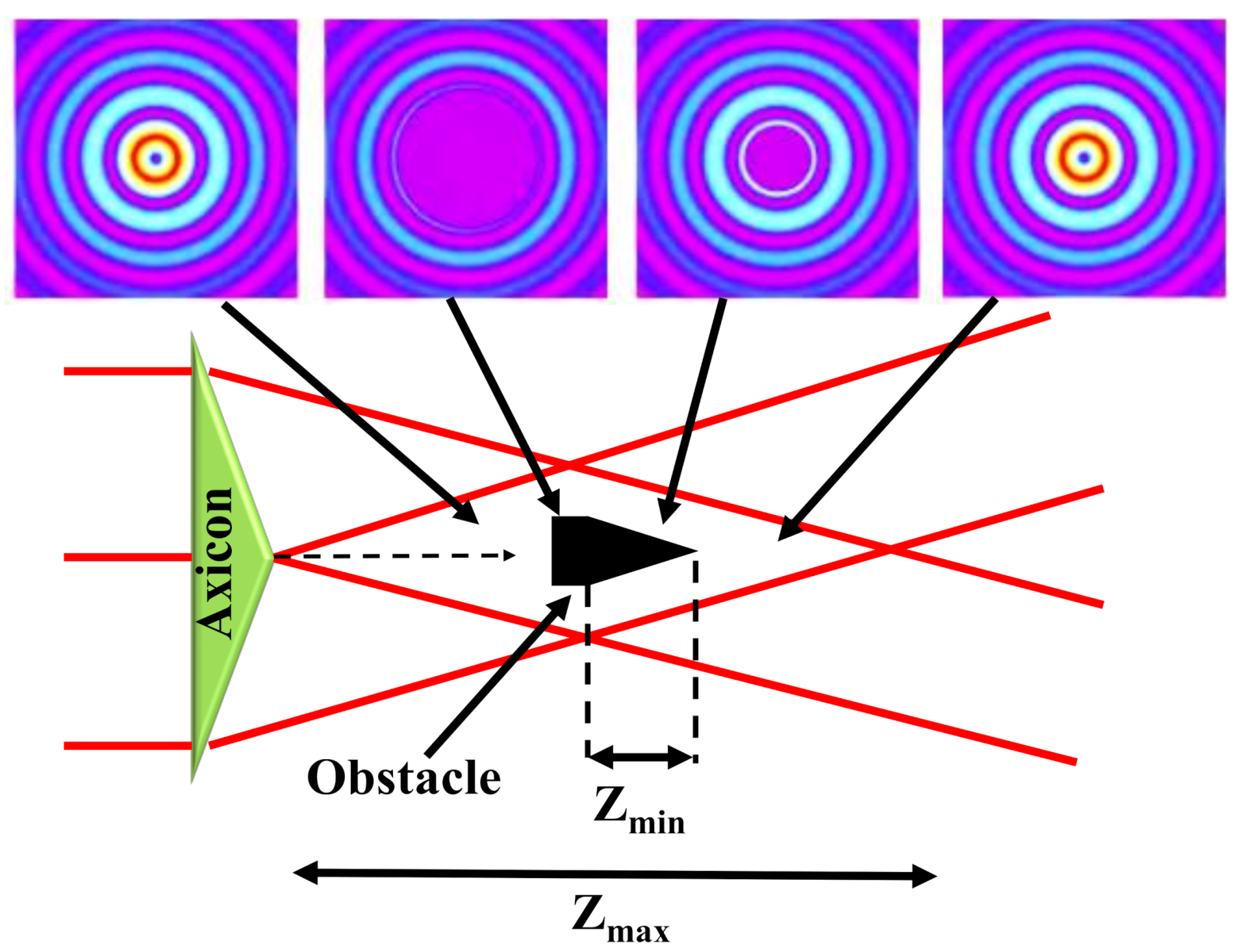
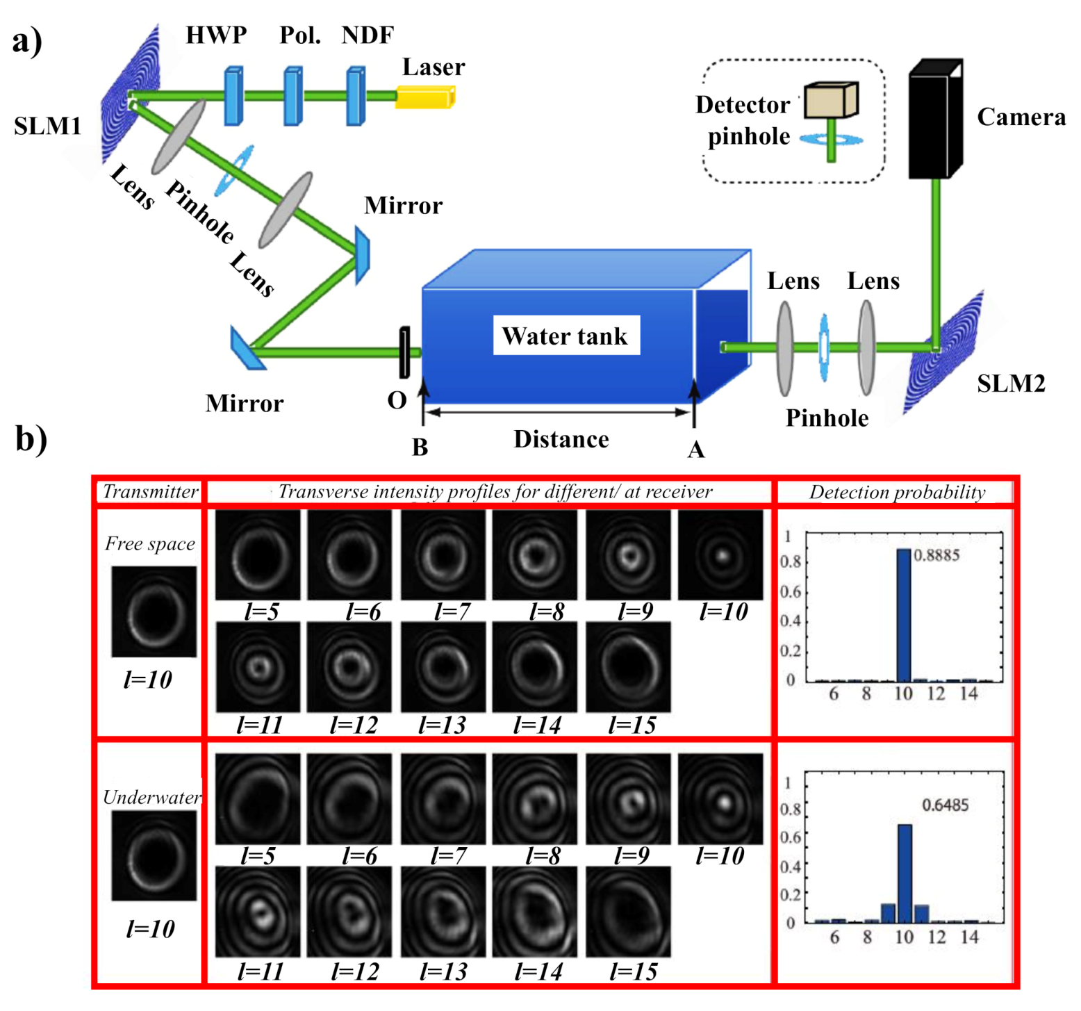
4. Free-Space Long-Distance Self-Healing BBs
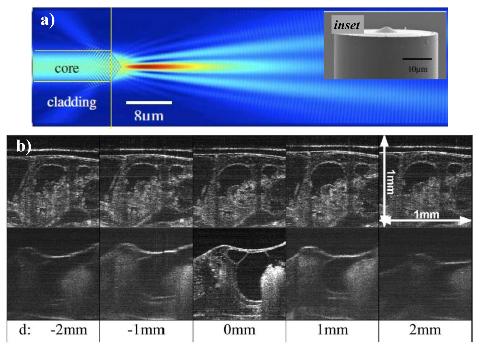
5. BB for Optical Coherence Tomography
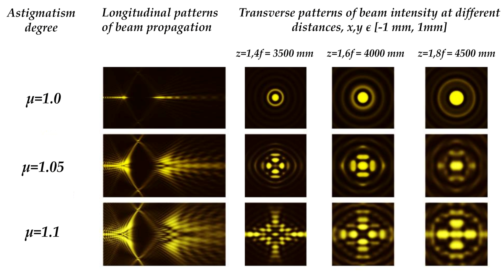
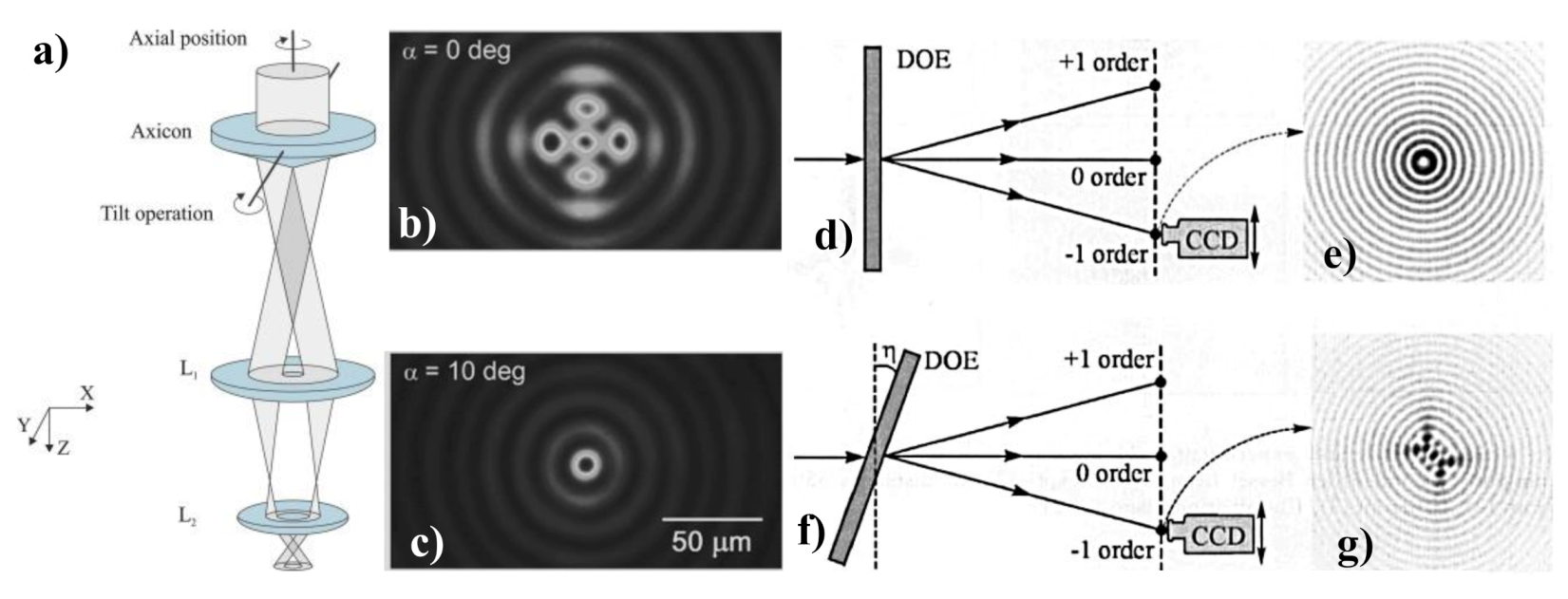
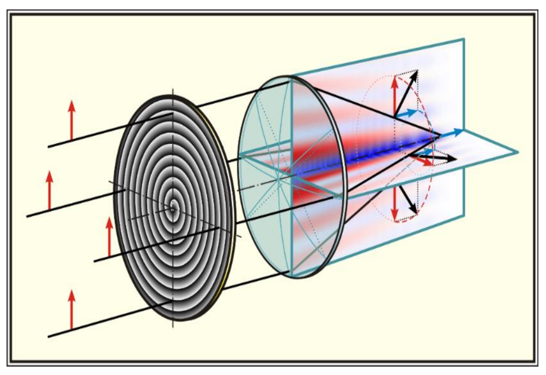
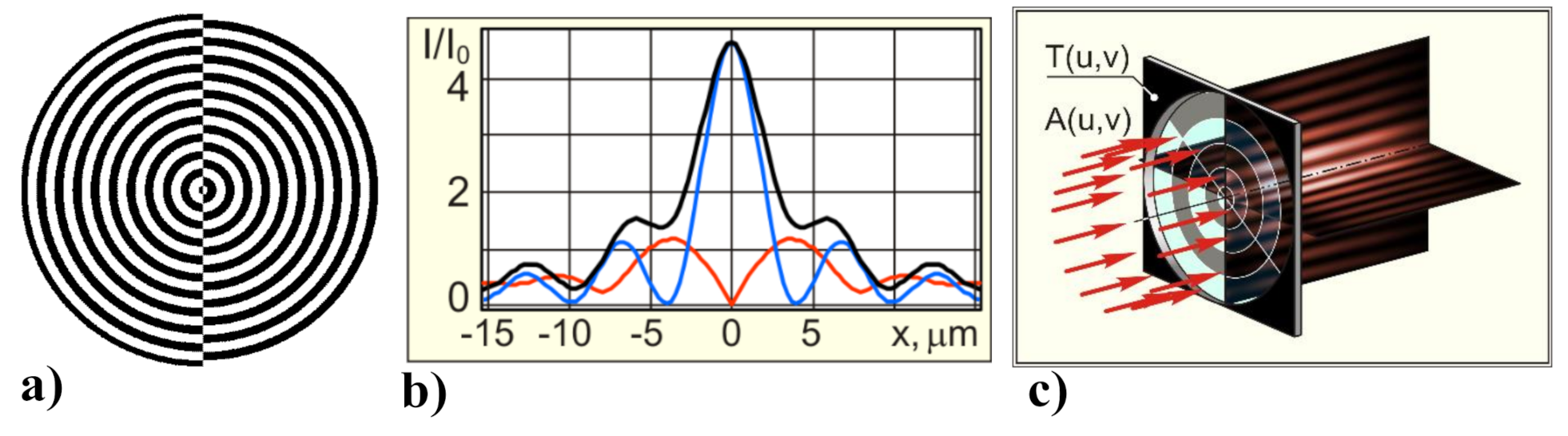
6. Birefringence Detection Based on Astigmatic Transformed BB
7. Tight or Sharp Focusing and Focal Shaping
7.1. Superresolution
7.2. Strengthening the Longitudinal Component
7.3. 3D Focal Shaping
8. Other Related Applications
9. Concluding Remarks
Author Contributions
Funding
Conflicts of Interest
References
- Durnin, J. Exact solutions for nondiffracting beams. I. The scalar theory. J. Opt. Soc. Am. A 1987, 4, 651–654. [Google Scholar] [CrossRef]
- Durnin, J.; Miceli, J.J., Jr.; Eberly, J.H. Diffraction-free beams. Phys. Rev. Lett. 1987, 58, 1499. [Google Scholar] [CrossRef]
- Lapointe, M.R. Review on non-diffracting Bessel beam experiments. Opt. Laser Technol. 1992, 24, 315–321. [Google Scholar] [CrossRef]
- Sokolovskii, G.; Dudelev, V.; Losev, S.; Soboleva, K.; Deryagin, A.; Fedorova, K.; Kuchinskii, V.; Sibbett, W.; Rafailov, E. Bessel beams from semiconductor light sources. Prog. Quantum Electron. 2014, 38, 157–188. [Google Scholar] [CrossRef]
- Khonina, S.N.; Kotlyar, V.V.; Soifer, V.A.; Shinkaryev, M.V.; Uspleniev, G.V. Trochoson. Opt. Commun. 1992, 91, 158–162. [Google Scholar] [CrossRef]
- Paterson, C.; Smith, R. Higher-order Bessel waves produced by axicon-type computer-generated holograms. Opt. Commun. 1996, 124, 121–130. [Google Scholar] [CrossRef]
- Fahrbach, A.R.F. Propagation stability of self-constructing Bessel beams enables contrast-enhanced imaging in thick media. Nat. Commun. 2011, 3, 632. [Google Scholar] [CrossRef] [PubMed]
- Li, Z.; Alici, K.B.; Caglayan, H.; Ozbay, E. Generation of an axially asymmetric Bessel-like beam from a metallic subwavelength aperture. Phys. Rev. Lett. 2009, 102, 143901. [Google Scholar] [CrossRef] [PubMed]
- Shi, C.; Dubois, M.; Wang, Y.; Zhang, X. High-speed acoustic communication by multiplexing orbital angular momentum. Proc. Natl. Acad. Sci. USA 2017, 114, 7250–7253. [Google Scholar] [CrossRef] [Green Version]
- Jiang, X.; Liang, B.; Cheng, J.C.; Qiu, C.W. Twisted acoustic: Metasurface-enabled multiplexing and demultiplexing. Adv. Mater. 2018, 30, 1800257. [Google Scholar] [CrossRef]
- Marston, P. Scattering of a Bessel beam by a sphere. J. Acous. Soc. Am. 2007, 121, 753. [Google Scholar] [CrossRef] [PubMed]
- Hsu, D.; Margetan, F.; Thompson, D. Bessel beam ultrasonic transducer: Fabrication method and experimental results. Appl. Phys. Lett. 1989, 55, 2066. [Google Scholar] [CrossRef]
- Lu, J.-Y.; Song, T.-K.; Kinnick, R.; Greenleaf, J. In vitro and in vivo real-time imaging with ultrasonic limited diffraction beams. IEEE Trans. Med. Imaging 1993, 12, 819–829. [Google Scholar] [CrossRef]
- Lu, J.-Y.; Xu, X.-L.; Zou, H.; Greenleaf, J. Application of Bessel beam for doppler velocity estimation. IEEE Trans. Ultrason. Ferroelectr. Freq. Control 1995, 42, 649–662. [Google Scholar] [CrossRef]
- Xu, N.; Liu, G.; Kong, Z.; Tan, Q. Creation of super-resolution hollow beams with long depth of focus using binary optics. Appl. Phys. Express 2019, 13, 012003. [Google Scholar] [CrossRef]
- Suarez, R.; Ambrosio, L.; Neves, A.; Zamboni-Rached, M.; Gesualdi, M. Experimental optical trapping with frozen waves. Opt. Lett. 2020, 45, 2514–2517. [Google Scholar] [CrossRef]
- Liu, Z.; Tang, X.; Zhang, Y.; Zhang, Y.; Ma, L.; Zhang, M.; Yang, X.; Zhang, J.; Yang, J.; Yuan, L. Simultaneous trapping of low-index and high microparticles using a single optical fiber Bessel beam. Opt. Lasers Eng. 2020, 131, 106119. [Google Scholar] [CrossRef]
- Porfirev, A. Realisation of active pulling/pushing laser beams for light-absorbing particles in the air with a pair of diffractive optical elements. Opt. Laser Technol. 2021, 133, 106584. [Google Scholar] [CrossRef]
- Ali, R.; Pinheiro, F.; Dutra, R.; Maia Neto, P. Tailoring optical pulling forces with composite microspheres. Phys. Rev. A 2020, 102, 023514. [Google Scholar] [CrossRef]
- Voitiv, A.; Andersen, J.; Siemens, M.; Lusk, M. Optical vortex braiding with Bessel beams. Opt. Lett. 2020, 45, 1321. [Google Scholar] [CrossRef]
- Qiu, S.; Ren, Y.; Liu, T.; Chen, L.; Wang, C.; Li, Z.; Shao, Q. Spinning object detection based on perfect optical vortex. Opt. Lasers Eng. 2020, 124, 105842. [Google Scholar] [CrossRef]
- Riaud, A.; Baudoin, M.; Thomas, J.-L.; Matar, O. Cyclones and attractive streaming generated by acoustical vortices. Phys. Rev. E 2014, 90, 013008. [Google Scholar] [CrossRef] [PubMed] [Green Version]
- Arita, Y.; Lee, J.; Kawaguchi, H.; Matsuo, R.; Miyamoto, K.; Dholakia, K.; Omatsu, T. Photopolymerization with high-order Bessel light beams. Opt. Lett. 2020, 45, 4080–4083. [Google Scholar] [CrossRef] [PubMed]
- Zannotti, A.; Denz, C.; Alonso, M.; Dennis, M. Shaping caustics into propagation-invariant light. Nat. Commun. 2020, 11, 3597. [Google Scholar] [CrossRef] [PubMed]
- Moshfeghi, M. Sidelobe suppression in annular array and axicon imaging systems. J. Acoust. Soc. Am. 1988, 83, 2202–2209. [Google Scholar] [CrossRef]
- Mikula, G.; Kolodziejczyk, A.; Makowski, M.; Prokopowicz, C.; Sypek, M. Diffractive elements for imaging with extended depth of focus. Opt. Eng. 2005, 44, 058001. [Google Scholar] [CrossRef]
- Arimoto, R.; Saloma, C.; Tanaka, T.; Kawata, S. Imaging properties of axicon in a scanning optical system. Appl. Opt. 1992, 31, 6653–6657. [Google Scholar] [CrossRef]
- Burvall, A.; Kolacz, K.; Goncharov, A.; Jaroszewicz, Z.; Dainty, C. Lens axicons in oblique illumination. Appl. Opt. 2007, 46, 312–318. [Google Scholar] [CrossRef]
- Sales, T.R.M.; Morris, G.M. Diffractive superresolution elements. J. Opt. Soc. Am. A 1997, 14, 1637–1646. [Google Scholar] [CrossRef]
- Bewersdorf, J.; Egner, A.; Hell, S.W. 4pi-confocal microscopy is coming of age. G.I.T. Imaging Microsc. 2004, 4, 24–25. [Google Scholar]
- Theriault, G.; Cottet, M.; Castonguay, A.; McCarthy, N.; Koninck, Y.D. Extended two-photon microscopy in live samples with Bessel beams: Steadier focus, faster volume scans, and simpler stereoscopic imaging. Front. Cell. Neurosci. 2014, 8, 139. [Google Scholar] [PubMed] [Green Version]
- Huisken, J.; Swoger, J.; Bene, F.D.; Wittbrodt, J.; Stelzer, E.H.K. Optical sectioning deep inside live embryos by selective plane microscopy. Science 2004, 305, 1007–1009. [Google Scholar] [CrossRef] [PubMed] [Green Version]
- Tomer, R.; Khairy, K.; Keller, P.J. Shedding light on the system: Studying embryonic development with light sheet microscopy. Curr. Opin. Genet. Dev. 2011, 21, 558–565. [Google Scholar] [CrossRef]
- Planchon, T.A.; Gao, L.; Milkie, D.E.; Davidson, M.W.; Galbraith, J.A.; Galbraith, G.A.; Betzig, E. Rapid three-dimensional isotropic imaging of living cells using Bessel beam plane illumination. Nat. Methods 2011, 8, 417–423. [Google Scholar] [CrossRef] [PubMed] [Green Version]
- Bassi, A.; Schmid, B.; Huisken, J. Optical tomography complements light sheet microscopy for in toto imaging of zebrafish development. Development 2015, 142, 1016–1020. [Google Scholar] [CrossRef] [PubMed] [Green Version]
- Aakhte, M.; Akhlagh, E.A.; Muller, J. SSPIM: A beam shaping toolbox for structured selective plane illumination microscopy. Sci. Rep. 2018, 8, 10067. [Google Scholar] [CrossRef] [Green Version]
- Hong, Z.; Zhang, J.; Drinkwater, B. Obervation of orbital angular momentum transfer from Bessel-shaped acoustic vortices to diphasic liquid-microparticle mixtures. Phy. Rev. Lett. 2015, 114, 214301. [Google Scholar] [CrossRef] [Green Version]
- Chillara, V.; Davis, E.; Pantea, C.; Sinha, D. Ultrasonic Bessel beam generation from radial modes of piezoelectric discs. Ultrasonics 2019, 96, 140–148. [Google Scholar] [CrossRef]
- Fewer, D.; Hewlett, S.; McCabe, E. Laser sources in direct-view-scanning, tandem-scanning, or Nipkow-disk-scanning confocal microscopy. Appl. Opt. 1998, 37, 380–385. [Google Scholar] [CrossRef]
- Campbell, J.; Soloway, S. Generation of a nondiffracting beam with frequency-independent beamwidth. J. Acoust. Soc. Am. 1990, 88, 2467–2477. [Google Scholar] [CrossRef]
- Chillara, V.; Pantea, C.; Sinha, D. Low-frequency ultrasonic Bessel-like collimated beam generation from radial modes of piezoelectric transducers. Appl. Phys. Lett. 2017, 110, 064101. [Google Scholar] [CrossRef]
- Sokolovskii, G.; Dudelev, V.; Losev, S.; Soboleva, K.; Deryagin, A.; Kuchinskii, V.; Sibbett, W.; Rafailov, E. Optical trapping with Bessel beams generated from semiconductor lasers. Phys. Conf. Ser. 2014, 572, 012039. [Google Scholar] [CrossRef] [Green Version]
- Sokolovskii, G.; Dudelev, V.; Losev, S.; Zolotovskaya, S.; Deryagin, A.; Kuchinskii, V.; Rafailov, E.; Sibbett, W. Generation of propagation-invariant light beams from semiconductor light sources. Tech. Phys. Lett. 2008, 34, 1075–1078. [Google Scholar] [CrossRef]
- Kozawa, Y.; Nara, Y.; Jikutani, N.; Higashi, Y.; Sato, S. Vector beam generation from vertical cavity surface emitting lasers. Opt. Lett. 2018, 43, 5659–5662. [Google Scholar] [CrossRef] [PubMed]
- Sokolovskii, G.; Zolotovskaya, S.; Losev, S.; Dudelev, V.; Deryagin, A.; Kuchinskii, V.; Sibbett, W.; Rafailov, E. High power Bessel beams from EP-VECSELs. In Proceedings of the SPIE LASE, 79190J, San Francisco, CA, USA, 21 February 2011. [Google Scholar]
- Khonina, S.; Kotlyar, V.; Skidanov, R.; Soifer, V.; Jefimovs, K.; Simonen, J.; Turunen, J. Rotation of microparticles with Bessel beams generated by diffractive elements. J. Mod. Opt. 2004, 51, 2167–2184. [Google Scholar] [CrossRef]
- Soifer, V.; Kotlyar, V.; Khonina, S.N. Optical microparticle manipulation: Advances and new possibilitiescreated by diffractive optics. Phys. Part. Nucl. 2004, 35, 733–766. [Google Scholar]
- Skidanov, R.; Khonina, S.N.; Porfirev, A.; Pavelyev, V.; Kachalov, D. Three-dimensional laser trapping on the base of binary radial diffractive optical element. J. Mod. Opt. 2015, 62, 1183–1186. [Google Scholar] [CrossRef]
- Khonina, S.N.; Kotlyar, V.; Soifer, V.; Lautanen, J.; Honkanen, M.; Turunen, J. Generating a couple of rotating nondiffracting beams using a binary-phase DOE. Optik 1999, 110, 137–144. [Google Scholar]
- Kuchmizhak, A.; Porfirev, A.; Syubaev, S.; Danilov, P.; Ionin, A.; Vitrik, O.; Kulchin, Y.; Khonina, S.N.; Kudryashov, S. Multi-beam pulsed-laser patterning of plasmonic films using broadband diffractive optical elements. Opt. Lett. 2017, 42, 2838–2841. [Google Scholar] [CrossRef]
- Syubaev, S.; Zhizhchenko, A.; Vitrik, O.; Porfirev, A.; Fomchenkov, S.; Khonina, S.N.; Kudryashov, S.; Kuchmizhak, A. Chirality of laser-printed plasmonic nanoneedles tunable by tailoring spiral shape pulses. Appl. Surf. Sci. 2019, 470, 526–534. [Google Scholar] [CrossRef]
- Khonina, S.N.; Golub, I. Tighter focus for ultrashort pulse vector light beams: Change of the relative contribution of different field components to the focal spot upon pulse shortening. J. Opt. Soc. Am. A 2018, 35, 985–991. [Google Scholar] [CrossRef] [PubMed]
- Khonina, S.N.; Ustinov, A.; Volotovsky, S. Comparison of focusing of short pulses in the Debye approximation. Comput. Opt. 2018, 42, 432–446. [Google Scholar] [CrossRef]
- Khonina, S.N.; Golub, I. Time behavior of focused vector beams. J. Opt. Soc. Am. A 2016, 33, 1948–1954. [Google Scholar] [CrossRef]
- Soifer, V.; Korotkova, O.; Khonina, S.N.; Shchepakina, E. Vortex beams in turbulent media. Comput. Opt. 2016, 40, 605–624. [Google Scholar] [CrossRef]
- Porfirev, A.; Kirilenko, M.; Khonina, S.; Skidanov, R.; Soifer, V. Study of propagation of vortex beams in aerosol optical medium. Appl. Opt. 2017, 56, E5–E15. [Google Scholar] [CrossRef] [PubMed]
- Vasilyev, V.; Kapustin, A.; Skidanov, R.; Podlipnov, V.; Ivliev, N.; Ganchevskaya, S. Experimental investigation of the stability of Bessel beams in the atmosphere. Comput. Opt. 2019, 43, 376–384. [Google Scholar] [CrossRef]
- Saadati-Sharafeh, F.; Borhanifar, A.; Porfirev, A.; Amiri, P.; Akhlaghi, E.; Khonina, S.N.; Azizian-Kalandaragh, Y. The superposition of the Bessel and mirrored Bessel beams and investigation of their self-healing characteristics. Optik 2020, 208, 164057. [Google Scholar] [CrossRef]
- Khonina, S.N.; Kotlyar, V.; Soifer, V.; Jefimovs, K.; Paakkonen, P.; Turunen, J. Astigmatic Bessel laser beams. J. Mod. Opt. 2004, 51, 677–686. [Google Scholar] [CrossRef]
- Khonina, S.N.; Paranin, V.; Ustinov, A.; Krasnov, A. Astigmatic transformation of Bessel beams in a uniaxial crystal. Opt. Appl. 2016, 46, 5–18. [Google Scholar]
- Khonina, S.N.; Karpeev, S.; Paranin, V. Birefringence detection of a gradient-index lens based on astigmatic transformation of a Bessel beam. Optik 2018, 164, 679–685. [Google Scholar] [CrossRef]
- Khonina, S.N. Simple way for effective formation various nondiffractive laser beams. Comput. Opt. 2009, 33, 70–78. [Google Scholar]
- Khonina, S.N.; Ustinov, A.; Chavez-Cerda, S. Generalized parabolic nondiffracting beams of two orders. J. Opt. Soc. Am. A 2018, 35, 1511–1517. [Google Scholar] [CrossRef] [PubMed]
- Khonina, S.N.; Ustinov, A.; Porfirev, A. Fractional two-parameter parabolic diffraction-free beams. Opt. Commun. 2019, 450, 103–111. [Google Scholar] [CrossRef]
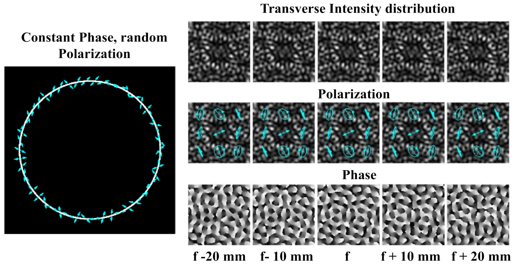
- Khonina, S.N.; Golub, I. Creating order with the help of randomness: Generating transversely random, longitudinally invariant vector optical fields. Opt. Lett. 2015, 40, 4070–4073. [Google Scholar] [CrossRef] [PubMed]
- Khonina, S.N.; Degtyarev, S. A longitudinally polarized beam generated by a binary axicon. J. Russ. Laser Res. 2015, 36, 151–161. [Google Scholar] [CrossRef]
- Khonina, S.N.; Ustinov, A.; Pelevina, E. Analysis of wave aberration influence on reducing focal spot size in a high aperture focusing system. J. Opt. 2011, 13, 095702. [Google Scholar] [CrossRef]
- Khonina, S.N.; Degtyarev, S.A. Analysis of the formation of a longitudinally polarized optical needle by a lens and axicon under tightly focused conditions. J. Opt. Technol. 2016, 83, 197–205. [Google Scholar] [CrossRef]
- Khonina, S.N.; Savelyev, D. High-aperture binary axicons for the formation of the longitudinal electric field component on the optical axis for linear and circular polarizations of the illuminating beams. J. Exp. Theor. Phys. 2013, 117, 623–630. [Google Scholar] [CrossRef]
- Khonina, S.N.; Ustinov, A. Sharper focal spot for a radially polarized beam using ring aperture with phase jump. J. Eng. 2013, 2013, 512971. [Google Scholar] [CrossRef] [Green Version]
- Ashkin, A. Acceleration and trapping of particles by radiation pressure. Phys. Rev. Lett. 1970, 24, 156. [Google Scholar] [CrossRef] [Green Version]
- Zemanek, P.; Volpe, G.; Jonas, A.; Brzobohaty, O. Perspective on light-induced transport of particles: From optical forces to phoretic motion. Adv. Opt. Photonics 2019, 11, 577–678. [Google Scholar] [CrossRef]
- Amako, J.; Sawaki, D.; Fujii, E. Microstructuring transparent materials by use of nondiffracting ultrashort pulse beams generated by diffractive optics. J. Opt. Soc. Am. B 2003, 20, 2562–2568. [Google Scholar] [CrossRef]
- Larsen, A.; Grier, D. Like-charge attractions in metastable colloidal crystallites. Nature 1997, 385, 230–233. [Google Scholar] [CrossRef]
- Garces-Chavez, V.; McGloin, D.; Melville, H.; Sibbett, W.; Dholakia, K. Simultaneous micromanipulation in multiple planes using a self-resonstructing light beam. Nature 2002, 419, 145–147. [Google Scholar] [CrossRef] [PubMed]
- Ayala, Y.A.; Arzola, A.V.; Volke-Sepúlveda, K. Comparative study of optical levitation traps: Focused Bessel beam versus Gaussian beams. J. Opt. Soc. Am. B 2016, 33, 1060–1067. [Google Scholar] [CrossRef]
- Garces-Chavez, V.; McGloin, D.; Padgett, M.J.; Dultz, W.; Schmitzer, H.; Dholakia, K. Observation of the transfer of the local angular momentum density of a multi-ringed light beam to an optically trapped particle. Phys. Rev. Lett. 2003, 91, 093602. [Google Scholar] [CrossRef]
- Volke-Sepulveda, K.P.; Garces-Chavez, V.; Chavez-Cerda, S.; Arlt, J.; Dholakia, K. Orbital angular momentum of a high-order Bessel light beam. J. Opt. B Quantum Semiclassical Opt. 2002, 4, S82–S89. [Google Scholar] [CrossRef]
- Volke-Sepulveda, K.; Chavez-Cerda, S.; Garces-Chavez, V.; Dholakia, K. Three-dimensional optical forces and transfer of orbital angular momentum from multi-ringed light beams to spherical microparticles. J. Opt. Soc. Am. B 2004, 21, 1749–1757. [Google Scholar] [CrossRef]
- Ashkin, A.; Dziedzic, J. Optical trapping and manipulation of viruses and bacteria. Science 1987, 235, 1517–1520. [Google Scholar] [CrossRef]
- Neuman, K.; Block, S. Optical Trapping. Rev. Sci. Instrum. 2004, 75, 2787–2809. [Google Scholar] [CrossRef]
- Omori, R.; Kobayashi, T.; Suzuki, A. Observation of a single-beam gradient-force optical trap for dielectric particles in air. Opt. Lett. 1997, 22, 816–818. [Google Scholar]
- Wills, J.; Knox, K.; Reid, J. Optical control and characterisation of aerosol. Chem. Phys. Lett. 2009, 481, 153–165. [Google Scholar]
- Lin, J.; Li, Y.-Q. Optical trapping and rotation of airborne absorbing particles with a single focused laser beam. Appl. Phys. Lett. 2014, 104, 101909. [Google Scholar]
- Gong, Z.; Pan, Y.-L.; Wang, C. Optical configurations for photophoretic trap of single particles in air. Rev. Sci. Instrum. 2016, 87, 103104. [Google Scholar] [PubMed]
- Desyatnikov, A.; Shvedov, V.; Rode, A.; Krolikowski, W.; Kivshar, Y. Photophoretic manipulation of absorbing aerosol particles with vortex beams: Theory versus experiment. Opt. Express 2009, 17, 8201–8211. [Google Scholar]
- Tung, J.; Ma, Y.; Miyamoto, K.; Chen, Y.; Omatsu, T. Bottle beam generation from a frequency-doubled Nd:YVO4 laser. Sci. Rep. 2018, 8, 16576. [Google Scholar]
- Spence, J.; Subramanian, G.; Musumeci, P. Hollow cone illumination for fast TEM, and outrunning damage with electrons. J. Phys. B At. Mol. Opt. Phys. 2015, 48, 214003. [Google Scholar]
- Liu, F.; Zhang, Z.; Wei, Y.; Zhang, Q.; Cheng, T.; Wu, X. Photophoretic trapping of multiple particles in tapered-ring optical field. Opt. Express 2014, 22, 23716–23723. [Google Scholar]
- Karpinski, P.; Jones, S.; Andren, D.; Kall, M. Counter-propagating optical trapping of resonant nanoparticles using a uniaxial crystal. Laser Photonics Rev. 2018, 12, 1800139. [Google Scholar]
- Ashkin, A. Optical trapping and manipulation of meutral particles using lasers. Proc. Natl. Acad. Sci. USA 1997, 94, 4853–4860. [Google Scholar]
- Redding, B.; Hill, S.; Alexson, D.; Wang, C.; Pan, Y.-L. Photophoretic trapping of airborne particles using ultraviolet illumination. Opt. Express 2015, 23, 3630–3639. [Google Scholar]
- Redding, B.; Pan, Y.-L. Optical trap for both transparent and absorbing particles in air using a single shaped laser beam. Opt. Lett. 2015, 40, 2798. [Google Scholar] [CrossRef]
- Dear, R.; Burnham, D.; Summers, M.; McGloin, D.; Ritchie, G. Single aerosol trapping with an annular beam improved particle localization. Phys. Chem. Chem. Phys. 2012, 14, 15826–15831. [Google Scholar]
- Roosen, G.; Imbert, C. Optical levitation by means of two horizontal laser beams: A theoretical and experimental study. Phys. Lett. A 1976, 59, 6–8. [Google Scholar] [CrossRef]
- Lewittes, M.; Arnold, S. Radiometric levitation of micron sized spheres. Appl. Phys. Lett. 1982, 40, 455. [Google Scholar]
- Courvoisier, F.; Zhang, J.; Bhuyan, M.K.; Jacquot, M.; Dudley, J.M. Applications of femtosecond Bessel beams to laser ablation. Appl. Phys. A 2013, 112, 29–34. [Google Scholar] [CrossRef]
- Duocastella, M.; Arnold, C.B. Bessel and annular beams for material processing. Laser Photonics Rev. 2012, 5, 607–621. [Google Scholar]
- Stoian, R.; Bhuyan, M.K.; Zhang, G.; Cheng, G.; Meyer, R.; Courvoisier, F. Ultrafast Bessel beams: Advanced tools for laser materials processing. Adv. Opt. Technol. 2018, 7, 165–174. [Google Scholar]
- Merano, M.; Boyer, G.; Trisorio, A.; Cheriaux, G.; Mourou, G. Superresolved femtosecond laser ablation. Opt. Lett. 2007, 32, 2239–2241. [Google Scholar]
- Butt, M.A.; Nguyen, H.-D.; Rodenas, A.; Romero, C.; Moreno, P.; De Aldana, J.; Aguilo, M.; Sole, R.; Pujol, M.; Diaz, F. Low-repitition rate femtosecond laser writing of optical waveguides in KTP crystals: Analysis of anisotropic refractive index changes. Opt. Express 2015, 23, 15343–15355. [Google Scholar]
- Sugioka, K.; Cheng, Y. Ultrafast lasers-reliable tools for advanced materials processing. Light Sci. Appl. 2014, 3, e149. [Google Scholar] [CrossRef]
- Liu, P.; Jiang, L.; Hu, J.; Yan, X.; Xia, B.; Lu, Y. Etching rate enhancement by shaped femtosecond pulse train electron dynamics control for microchannels fabrication in fused silica glass. Opt. Lett. 2013, 38, 4613–4616. [Google Scholar] [CrossRef]
- Vishnubhatla, K.; Bellini, N.; Ramponi, R.; Cerullo, G.; Osellame, R. Shape control of microchannels fabricated in fused silica by femtosecond laser irradiated and chemical etching. Opt. Express 2009, 17, 8685–8695. [Google Scholar]
- Wang, Z.; Jiang, L.; Li, X.; Wang, A.; Yao, Z.; Zhang, K.; Lu, Y. High-throughput microchannel fabrication in fused silica by temporally shaped femtosecond laser Bessel-beam-assisted chemical etching. Opt. Lett. 2018, 43, 98–101. [Google Scholar] [CrossRef]
- Chu, X.; Sun, Q.; Wang, J.; Lu, P.; Xie, W.; Xu, X. Generating a Bessel-Gaussian beam for the application in optical engineering. Sci. Rep. 2016, 5, 18665. [Google Scholar] [CrossRef]
- Mikutis, M.; Kudrius, T.; Slekys, G.; Paipulas, D.; Juodkazis, S. High 90% efficiency Bragg gratings formed in fused silica by femtosecond Gauss-Bessel laser beams. Opt. Mater. Express 2013, 3, 1862–1871. [Google Scholar] [CrossRef]
- Bhuyan, M.; Courvoisier, F.; Lacourt, P.; Jacquot, M.; Furfaro, L. High aspect ratio taper-free microchannel fabrication using femtosecond Bessel beams. Opt. Express 2010, 18, 566–574. [Google Scholar] [CrossRef]
- Yang, L.; El-Tamer, A.; Hinze, U.; Li, J.; Hu, Y.; Huang, W.; Chu, J.; Chichkov, B. Two-photon polymerization of cylinder microstructures by femtosecond Bessel beams. Appl. Phys. Lett. 2014, 105, 041110. [Google Scholar] [CrossRef]
- Slevas, P.; Orlov, S.; Nacius, E.; Ulcinas, O.; Gotovski, P.; Baltrukonis, J.; Jukna, V. Laser induced modifications in transparent materials using azimuthally modulated axicon beams. In Proceedings of the SPIE 11267, Laser Applications in Microelectronic and Optoelectronic Manufacturing (LAMOM) XXV, 112670B, San Francisco, CA, USA, 2 March 2020. [Google Scholar]
- Baltrukonis, J.; Ulcinas, O.; Gotovski, P.; Orlov, S.; Jukna, V. Realization of higher order vector Bessel beams for transparent material processing applications. In Proceedings of the SPIE 11268, Laser-based Micro- and Nanoprocessing XIV, 112681D, San Francisco, CA, USA, 2 March 2020. [Google Scholar]
- Song, C.; Wang, Z.; Chen, Q.; Cai, J.; Liu, L. High aspect ratio copper through-silicon-vias for 3D integration. Microelectron. Eng. 2008, 85, 1952–1956. [Google Scholar] [CrossRef]
- Tan, B. Deep micro hole drilling in a silicon substrate using multi-bursts of nanosecond UV laser pulses. J. Micromech. Microeng. 2006, 16, 109–112. [Google Scholar] [CrossRef]
- He, F.; Xu, H.; Cheng, Y.; Ni, J.; Xiong, H.; Xu, Z.; Sugioka, K.; Midorikawa, K. Fabrication of microfluidic channels with a circular cross section using spatiotemporally focused femtosecond laser pulses. Opt. Lett. 2010, 35, 1106–1108. [Google Scholar] [CrossRef] [PubMed]
- Barsch, N.; Korber, K.; Ostendorf, A.; Tonshoff, K. Ablation and cutting of planar silicon devices using femtosecond laser. Appl. Phys. 2003, 77, 237–242. [Google Scholar] [CrossRef]
- He, F.; Yu, J.; Chu, W.; Wang, Z.; Tan, Y.; Cheng, Y.; Sugioka, K. Tailored femtosecond Bessel beams for high-throughput, taper-free through-Silicon vias (TSVs) fabrication. In Proceedings of the SPIE 9735, 973506–1, San Francisco, CA, USA, 14 March 2016. [Google Scholar]
- He, F.; Yu, J.; Tan, Y.; Chu, W.; Zhou, C.; Cheng, Y.; Sugioka, K. Tailoring femtosecond 1.5 mm Bessel beams for manufacturing high-aspect-ratio through-silicon vias. Sci. Rep. 2017, 7, 40785. [Google Scholar] [CrossRef] [PubMed]
- Li, S.; Wang, J. Adaptive free-space optical communications through turbulence using self-healing Bessel beams. Sci. Rep. 2017, 7, 43233. [Google Scholar] [CrossRef] [PubMed]
- Bouchal, Z. Nondiffracting optical beams: Physical properties, experiments, and applications. Czechoslov. J. Phys. 2003, 53, 537–578. [Google Scholar] [CrossRef] [Green Version]
- Wiersma, N. Photorefractive Self-Focusing of Airy Beams: Nonlinear Interactions and All-Optical Waveguiding. Ph.D. Thesis, Universite de Lorraine, Nancy, France, 2016. [Google Scholar]
- Vetter, C.; Steinkopf, R.; Bergner, K.; Ornigotti, M.; Nolte, S.; Gross, H.; Szameit, A. Realization of Free-space long-distance self-healing Bessel beams. Laser Photonics Rev. 2019, 13, 1900103. [Google Scholar] [CrossRef]
- Kaushal, H.; Kaddoum, G. Underwater optical wireless communication. IEEE Access 2016, 4, 1518–1547. [Google Scholar] [CrossRef]
- Saeed, N.; Celik, A.; Al-Naffouri, T.Y.; Alouini, M.-S. Underwater optical wireless communications, networking, and localization: A survey. Ad Hoc Netw. 2019, 94, 101935. [Google Scholar] [CrossRef] [Green Version]
- Spagnolo, G.S.; Cozzella, L.; Leccese, F. Underwater optical wireless communications: Overview. Sensors 2020, 20, 2261. [Google Scholar] [CrossRef]
- Xu, J.; Zhao, D. Propagation of a stochastic electromagnetic vortex beam in the oceanic turbulence. Opt. Laser Technol. 2014, 57, 189–193. [Google Scholar] [CrossRef]
- Huang, Y.; Zhang, B.; Gao, Z.; Zhao, G.; Duan, Z. Evolution behavior of gaussian schell-model vortex beams propagation through oceanic turbulence. Opt. Express 2014, 22, 17723–17734. [Google Scholar] [CrossRef] [PubMed]
- Xiang, Y.; Zheng, R.; Yue, P.; Ding, W.; Shen, C. Propagation properties of OAM modes carried by partially coherent LG beams in turbulent ocean based on an oceanic power-law spectrum. Opt. Commun. 2019, 443, 238–244. [Google Scholar]
- Cheng, M.; Guo, L.; Li, J.; Huang, Q.; Cheng, Q.; Zhang, D. Propagation of an optical vortex carried by a partially coherent Laguerre-Gaussian beam in turbulent ocean. Appl. Opt. 2016, 55, 4642–4648. [Google Scholar] [CrossRef] [PubMed]
- Cheng, M.; Guo, L.; Li, J.; Zhang, Y. Channel capacity of the oam-based free-space optical communication links with bessel-gauss beams in turbulent ocean. IEEE Photonics J. 2017, 8, 1–11. [Google Scholar] [CrossRef]
- Ou, J.; Jiang, Y.; Zhang, J.; Tang, H.; He, Y.; Wang, S.; Liao, J. Spreading of spiral spectrum of bessel-gaussian beam in non-kolmogorov turbulence. Opt. Commun. 2014, 318, 95–99. [Google Scholar] [CrossRef]
- Zhao, S.; Zhang, W.; Wang, L.; Li, W.; Gong, L.; Cheng, W.; Chen, H.; Gruska, J. Propagation and self-healing properties of Bessel-Gaussian beam carrying orbital angular momentum in an underwater environment. Sci. Rep. 2019, 9, 2025. [Google Scholar] [CrossRef] [Green Version]
- Willner, A.; Zhao, Z.; Ren, Y.; Li, L.; Xie, G.; Song, H.; Liu, C.; Zhang, R.; Bao, C.; Pang, K. Underwater optical communications using orbital angular momentum-based spatial division multiplexing. Opt. Commun. 2018, 408, 21–25. [Google Scholar] [CrossRef]
- Fu, S.; Gao, C. Influence of atmospheric turbulence effetcs on the orbital angular momentum spectra of vortex beams. Photonics Res. 2016, 4, B1. [Google Scholar] [CrossRef] [Green Version]
- Zhou, G.; Tang, H.; Zhu, K.; Zheng, X.; Li, X. Propagation of bessel-gaussian beams with optical vortices in turbulent atmosphere. Opt. Express 2008, 16, 21315–21320. [Google Scholar] [CrossRef]
- Wang, J.; Du, J. High-dimensional structured light coding/decoding for free-space optical communications free of obstructions. Opt. Lett. 2015, 40, 4827–4830. [Google Scholar]
- Fujimoto, J.; Pitris, C.; Boppart, S.; Brezinski, M. Optical coherence tomography: An emerging technology for biomedical imaging and optical biopsy. Neoplasia 2000, 2, 9–25. [Google Scholar] [CrossRef] [PubMed] [Green Version]
- Xie, T.; Guo, S.; Chen, Z.; Mukai, D.; Brenner, M. GRIN lens rod based probe for endoscopic spectral domain optical coherence tomography with fast dynamic focus tracking. Opt. Express 2006, 14, 3238–3246. [Google Scholar] [CrossRef] [PubMed]
- Murali, S.; Lee, K.; Rolland, J. Invariant resolution dynamic focus OCM based on liquid crystal lens. Opt. Express 2007, 15, 15854–15862. [Google Scholar] [CrossRef] [PubMed]
- Asami, T.; Terasaki, H.; Ito, Y.; Sugita, T.; Kaneko, H.; Nishiyama, J.; Namiki, H.; Kobayashi, M.; Nishizawa, N. Development of a Fiber-Optic Optical Coherence Tomography Probe for Intraocular Use. Investig. Ophthalmol. Vis. Sci. 2016, 57, OCT568–OCT574. [Google Scholar] [CrossRef] [Green Version]
- McLeod, J. The Axicon: A new type of optical element. J. Opt. Soc. Am. 1954, 44, 592–597. [Google Scholar] [CrossRef]
- Lorenser, D.; Singe, C.; Curatolo, A.; Sampson, D. Energy-efficient low-Fresnel-number Bessel beams and their application in optical coherence tomography. Opt. Lett. 2014, 39, 548–551. [Google Scholar] [CrossRef]
- Yi, L.; Sun, L.; Ding, W. Multifocal spectral-domain optical coherence tomography based on Bessel beam for extended imaging depth. J. Biomed. Opt. 2017, 22, 106016. [Google Scholar]
- Yin, B.; Hyun, C.; Gardecki, J.; Tearney, G. Extended depth of focus for coherence-based cellular imaging. Optica 2017, 4, 959–965. [Google Scholar] [CrossRef] [Green Version]
- Ding, Z.; Ren, H.; Zhao, Y.; Nelson, J.; Chen, Z. High-resolution optical coherence tomography over a large depth range with an axicon lens. Opt. Lett. 2002, 27, 243–245. [Google Scholar] [CrossRef]
- Leitgeb, R.; Villiger, M.; Bachmann, A.; Steinmann, L.; Lasser, T. Extended focus depth for Fourier domain optical coherence microscopy. Opt. Lett. 2006, 31, 2450–2452. [Google Scholar] [CrossRef] [Green Version]
- Lee, K.-S.; Rolland, J. Bessel beam spectral-domain high-resolution optical coherence tomography with micro-optic axicon providing extended focusing range. Opt. Lett. 2008, 33, 1696–1698. [Google Scholar] [CrossRef] [PubMed] [Green Version]
- Arlt, J.; Dholakia, K. Generation of high-order Bessel beams by use of an axicon. Opt. Commun. 2000, 177, 297–301. [Google Scholar] [CrossRef]
- McGloin, D.; Dholakia, K. Bessel beams: Diffraction in a new light. Contemp. Phys. 2005, 46, 15–28. [Google Scholar] [CrossRef]
- Tan, K.; Mazilu, M.; Chow, T.H.; Lee, W.M.; Taguichi, K.; Ng, B.K.; Sibbett, W.; Herrington, C.S.; Brown, C.T.A.; Dholakia, K. In-fiber common-path optical coherence tomography using a conical-tip fiber. Opt. Express 2009, 17, 2375–2384. [Google Scholar] [CrossRef]
- Schwarz, S.; Roth, G.-L.; Rung, S.; Esen, C.; Hellmann, R. Fabrication and evaluation of negative axicons for ultrashort pulsed laser applications. Opt. Express 2020, 28, 26207–26217. [Google Scholar] [CrossRef]
- Ruan, H.; Wang, L.; Wu, S.; Liu, L.; Zhou, B. Free space vortex light by diffraction of a Bessel Beam from Optical Fiber. IEEE Photonics J. 2017, 9, 1–10. [Google Scholar] [CrossRef]
- Vairagi, K.; Minz, R.A.; Kaur, S.; Kumbhakar, D.; Paul, S.; Tiwari, U.; Sinha, R.; Fick, J.; Mondal, S. Deep seated negative axicon in selective optical fiber tip and collimated Bessel beam. IEEE Photonics Technol. Lett. 2017, 29, 786–789. [Google Scholar] [CrossRef]
- Stuker, F.; Ripoll, J.; Rudin, M. Fluorescence molecular tomography: Principles and potential for pharmaceutical research. Pharmaceutics 2011, 3, 229–274. [Google Scholar] [CrossRef]
- Rouke, J.; Moore, D. Birefringence measurements in gradient-index rod lenses. Appl. Opt. 1999, 38, 6574–6580. [Google Scholar] [CrossRef]
- Camacho, J.; Tentori, D. Polarization optics of GRIN lenses. J. Opt. A 2001, 3, 89–95. [Google Scholar] [CrossRef]
- Wei, S.; Gilbert, J. Birefringent properties of diametrically loaded gradient-index lenses. Appl. Opt. 1996, 35, 4772–4781. [Google Scholar]
- Rouke, J.; Moore, D. Birefringence in gradient-index rod lenses: A direct measurement method and interferometric polarization effects. Appl. Opt. 2001, 40, 4971–4980. [Google Scholar] [CrossRef] [PubMed]
- Dudutis, J.; Stonys, R.; Raciukaitis, G.; Gecys, P. Glass dicing with elliptical Bessel beam. Opt. Laser Technol. 2019, 111, 331–337. [Google Scholar] [CrossRef]
- Quabis, S.; Dorn, R.; Eberler, M.; Glockl, O.; Leuchs, G. Focusing light to a tighter spot. Opt. Commun. 2000, 179, 1–7. [Google Scholar] [CrossRef]
- Dorn, R.; Quabis, S.; Leuchs, G. Sharper focus for a radially polarized light beam. Phys. Rev. Lett. 2003, 91, 2339011–2339014. [Google Scholar] [CrossRef] [PubMed]
- Sheppard, C.; Choudhury, A. Annular pupils, radial polarization, and superresolution. Appl. Opt. 2004, 43, 4322–4327. [Google Scholar] [CrossRef]
- Pereira, S.; Nes, A.V.D. Superresolution by means of polarisation, phase and amplitude pupil masks. Opt. Commun. 2004, 234, 119–124. [Google Scholar] [CrossRef]
- Kozawa, Y.; Sato, S. Sharper focal spot formed by higher order radially polarized laser beams. J. Opt. Soc. Am. A 2007, 24, 1793–1798. [Google Scholar] [CrossRef]
- Khonina, S.N. Simple phase optical elements for narrowing of a focal spot in high-numerical-aperture conditions. Opt. Eng. 2013, 52, 091711. [Google Scholar] [CrossRef]
- Lerman, G.; Levy, V. Effect of radial polarization and apodization on spot size under tight focusing conditions. Opt. Express 2008, 16, 4567–4581. [Google Scholar] [CrossRef]
- Zhan, Q. Cylindrical vector beams: From mathematical concepts to applications. Adv. Opt. Photon. 2009, 1, 1–57. [Google Scholar] [CrossRef]
- Chen, Z.; Hua, L.; Pu, J. Tight focusing of light beams: Effect of polarization, phase and coherence. Prog. Opt. 2012, 57, 219–260. [Google Scholar]
- Khonina, S.N.; Alferov, S.; Karpeev, S. Strengthening the longitudinal component of the sharply focused electric field by means of higher-order laser beams. Opt. Lett. 2013, 38, 3223–3226. [Google Scholar] [CrossRef] [PubMed]
- Novotny, L.; Beversluis, M.; Youngworth, K.; Brown, T. Longitudinal field modes probed by single molecules. Phys. Rev. Lett. 2001, 86, 5251–5254. [Google Scholar] [CrossRef] [PubMed] [Green Version]
- Yew, E.; Sheppard, C. Second harmonic generation polarization microscopy with tightly focused linearly and radially polarized beams. Opt. Commun. 2007, 275, 453–457. [Google Scholar] [CrossRef]
- Hayazawa, N.; Saito, Y.; Kawata, S. Detection and characterization of longitudinal field for tip-enhanced Raman spectroscopy. Appl. Phys. Lett. 2004, 85, 6239–6241. [Google Scholar] [CrossRef]
- Bochkarev, S.; Popov, K.; Bychenkov, V. Vacuum electron acceleration by a tightly focused radially polarized, relativistically strong laser pulse. Plasma Phys. Rep. 2011, 37, 603–614. [Google Scholar] [CrossRef]
- Sun, C.; Liu, C. Ultrasmall focusing spot with a long depth of focus based on polarization and phase modulation. Opt. Lett. 2003, 28, 99–101. [Google Scholar] [CrossRef]
- Wang, H.; Shi, L.; Lukyanchuk, B.; Sheppard, C.; Chong, C. Creation of a needle of longitudinally polarized light in vacuum using binary optics. Nat. Photonics 2008, 2, 501–505. [Google Scholar] [CrossRef]
- Rajesh, K.; Jaroszewicz, Z.; Anbarasan, P. Improvement of lens axicon’s performance for longitudinally polarized beam generation by adding a dedicated phase transmittance. Opt. Express 2010, 18, 26799–26805. [Google Scholar] [CrossRef]
- Huang, K.; Shi, P.; Kang, X.; Zhang, X.; Li, Y. Design of DOE for generating a needle of a strong longitudinally polarized light. Opt. Lett. 2010, 35, 965–967. [Google Scholar] [CrossRef] [PubMed]
- Khonina, S.N.; Karpeev, S.; Alferov, S.; Savelyev, D.; Laukkanen, J.; Turunen, J. Experimental demonstration of the generation of the longitudinal E-field components on the optical axis with high-numerical-aperture binary axicons illuminated by linearly and circularly polarized beams. J. Opt. 2013, 15, 085704. [Google Scholar] [CrossRef]
- Chen, W.; Zhan, Q. Three-dimensional focus shaping with cylindrical vector beams. Opt. Commun. 2006, 265, 411–417. [Google Scholar] [CrossRef]
- Bokor, N.; Davidson, N. A three dimensional dark focal spot uniformly surrounded by light. Opt. Commun. 2007, 279, 229–234. [Google Scholar] [CrossRef]
- Wang, X.; Ding, J.; Qin, J.; Chen, J.; Fan, Y.; Wang, H. Configurable three-dimensional optical cage generated from cylindrical beams. Opt. Commun. 2009, 282, 3421–3425. [Google Scholar] [CrossRef]
- Khonina, S.N.; Golub, I. Ultrafast rotating dipole or propeller-shaped patterns: Subwavelength shaping of a beam of light on a femtosecond time scale. Opt. Lett. 2016, 41, 1605–1607. [Google Scholar] [CrossRef]
- Khonina, S.N.; Golub, I. Generation of an optical ball bearing facilitated by coupling between handedness of polarization of light and helicity of its phase. J. Opt. Soc. Am. B 2019, 36, 2087–2091. [Google Scholar] [CrossRef]
- Wang, J.; Chen, W.; Zhan, Q. Creation of uniform three-dimensional optical chain through tight focusing of space variant polarized beams. J. Opt. 2012, 14, 055004. [Google Scholar] [CrossRef]
- Khonina, S.N.; Ustinov, A.V. Interference analysis of radially polarized laser beams generated by ring optical elements with vortical phases under at sharp focusing. Opt. Mem. Neutral Netw. 2015, 24, 130–144. [Google Scholar] [CrossRef]
- Khonina, S.N.; Golub, I. Engineering the smallest 3D symmetrical bright and dark focal spots. J. Opt. Soc. Am. A 2013, 30, 2029–2033. [Google Scholar] [CrossRef]
- Khonina, S.N.; Ustinov, A.V.; Volotovsky, S.G. Shaping of spherical light intensity based on the interference of tightly focused beams with different polarizations. Opt. Laser Technol. 2014, 60, 99–106. [Google Scholar] [CrossRef]
- Fujiwara, J. Optical Properties of Conic Surfaces. I. Reflecting Cone. J. Opt. Soc. Am. 1962, 52, 287–292. [Google Scholar] [CrossRef]
- Soroko, L.M. Axicons and Meso-Optical Imaging Devices. Prog. Opt. 1989, 27, 109–160. [Google Scholar]
- Jaroszewicz, Z.; Sochacki, J.; Kolodziejczyk, A.; Staronski, L.R. Apodized Annular-Aperture Logarithmic Axicon: Smoothness and Uniformity of Intensity Distribution. Opt. Lett. 1993, 18, 1893–1895. [Google Scholar] [CrossRef]
- Golub, I.; Chebbi, B.; Shaw, D.; Nowacki, D. Characterization of a Refractive Logarithmic Axicon. Opt. Lett. 2010, 35, 2828–2830. [Google Scholar] [CrossRef]
- Sochacki, J.; Kolodziejczyk, A.; Jaroszewicz, Z.; Bara, S. Nonparaxial Design of Generalized Axicon. Appl. Opt. 1992, 31, 5326–5330. [Google Scholar] [CrossRef]
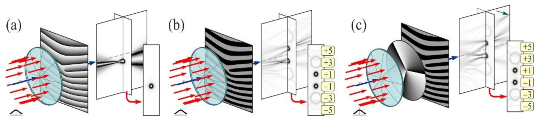
- Kotylar, V.V.; Kovalev, A.A.; Skidanov, R.V.; Moiseev, O.Y.; Soifer, V.A. Diffraction of a finite radius plane wave and a Guassian beam by a helical axicon and a spiral phase plate. J. Opt. Soc. Am. A. 2007, 24, 1955–1964. [Google Scholar] [CrossRef]
- Kazanskiy, N.L. Modeling diffractive optics elements and devices. In Proceedings of the SPIE 10774, 107740O-1, Optical Technologies in Telecommunications, Kazan, Russia, 6 June 2018. [Google Scholar]
- Dyson, J. Circular and spiral diffraction gratings. Proc. R. Soc. A 1958, 248, 93–106. [Google Scholar]
- Koronkevich, V.P.; Mikhaltsova, I.A.; Churin, E.G.; Yurlov, Y.I. Lensacon. Appl. Opt. 1993, 34, 5761–5772. [Google Scholar] [CrossRef]
- Khonina, S.N.; Kazanskiy, N.L.; Ustinov, A.V.; Volotovskiy, S.G. The lensacon: Nonparaxial effects. J. Opt. Technol. 2011, 78, 724–729. [Google Scholar] [CrossRef]
- Lenkova, G.A.; Korolkov, V.P.; Koronkevich, V.P.; Nasyrov, R.K.; Gutman, A.S.; Iskakov, I.A.; Treushnikov, V.M. Diffractive-refractive intraocular lenses. Optoelectron. Instrum. Data Process. 2008, 44, 342–352. [Google Scholar] [CrossRef]
- Lenkova, G.A. Spatial-energy characteristics of the focal areas of bifocal diffractive-refractive intraocular lenses. Optoelectron. Instrum. Data Process. 2017, 53, 68–76. [Google Scholar] [CrossRef]
- Belanger, P.; Rioux, M. Ring pattern of a lens-axicon doublet illuminated by a Guassian beam. Appl. Opt. 1978, 17, 1080–1088. [Google Scholar] [CrossRef] [PubMed]
- de Angeles, M.; Cacciapuoti, L.; Pierattini, G.; Tino, G.M. Axially symmetric hollow beams using refractive conical lenses. Opt. Lasers Eng. 2003, 39, 283–291. [Google Scholar] [CrossRef] [Green Version]
- Ren, Q.; Birngruber, R. Axicon: A new laser beam delivery system for corneal surgery. IEEE J. Quantum Electron. 1990, 26, 2305–2308. [Google Scholar] [CrossRef]
- Anguiano-Morales, M.; Martinez, A.; Iturbe-Castillo, M.; Chavez-Cerda, S. Different field distributions obtained with an axicon and an amplitude mask. Opt. Commun. 2008, 281, 401–407. [Google Scholar] [CrossRef]
- Cottrell, D.; Craven, J.; Davis, J. Nondiffracting random intensity patterns. Opt. Lett. 2007, 32, 298–300. [Google Scholar] [CrossRef]
- Maluenda, D.; Carnicer, A.; Martinez-Herrero, R.; Juvells, I.; Javidi, B. Optical encryption using photon-counting polarimetric imaging. Opt. Express 2015, 23, 655–666. [Google Scholar] [CrossRef] [Green Version]
- Carnicer, A.; Juvells, I.; Javidi, B.; Martinez-Herrero, R. Optical encryption in the longitudinal domain of focused fields. Opt. Express 2016, 24, 6793. [Google Scholar] [CrossRef]
- Biener, G.; Niv, A.; Kleiner, V.; Hasman, E. Geometrical phase image encryption obtained with space-variant subwavelength gratings. Opt. Lett. 2005, 30, 1096–1098. [Google Scholar] [CrossRef]
- Martinez-Herrero, R.; Juvells, I.; Carnicer, A. Design of highly focused fields that remain unpolarized on axis. Opt. Lett. 2014, 39, 6025–6028. [Google Scholar] [CrossRef] [PubMed] [Green Version]
- Liang, C.; Zhao, C.; Zhao, C.; Wang, K.; Cai, Y. Degree of polarization of a tightly focused, partiallycoherent anomalous hollow beam. J. Opt. Soc. Am. A 2014, 31, 2753–2758. [Google Scholar] [CrossRef] [PubMed]
- Ren, H.; Li, X.; Gu, M. Polarization-multiplexed multifocal arrays by a π-phase-step-modulated azimuthally polarized beam. Opt. Lett. 2014, 39, 6771–6774. [Google Scholar] [CrossRef] [PubMed]
- Ostrovsky, A.; Rickenstorff-Parrao, C.; Arrizon, V. Generation of the “perfect” optical vortex using a liquid-crystal spatial light modulator. Opt. Lett. 2013, 38, 534–536. [Google Scholar] [CrossRef] [PubMed]
- Chen, M.; Mazilu, M.; Arita, Y.; Wright, E.; Dholakia, K. Dynamics of micro particles trapped in a perfect vortex beam. Opt. Lett. 2013, 38, 4919–4922. [Google Scholar] [CrossRef]
- Rickenstorff, C.; Garcia-Garcia, J.; Sampayo-Martinez, A.; Ostrovsky, A.; Arrizon, A. Generation of the “Perfect” vortex for optical trapping. In Frontiers in Optics; OSA: Orlando, FL, USA, 2013. [Google Scholar]
- Vaity, P.; Rusch, L. Perfect vortex beam: Fourier transformation of a Bessel beam. Opt. Lett. 2015, 40, 597–600. [Google Scholar] [CrossRef]
- Golub, M.A.; Kazanskiy, N.L.; Sisakyan, I.N.; Soifer, V.A.; Kharitonov, S.I. Diffraction calculation for an optical element which focuses into a ring. Optoelectron. Instrum. Data Process 1987, 23, 7–14. [Google Scholar]
- Garcia-Garcia, J.; Rickenstorff-Parrao, C.; Ramos-Garcia, R.; Arrizon, V.; Ostrovsky, A. Simple technique for generating the perfect optical vortex. Opt. Lett. 2014, 39, 5305–5308. [Google Scholar] [CrossRef]
- Kotlyar, V.A.; Kovalev, A.; Porfirev, A. Optimal phase element for generating a perfect optical vortex. J. Opt. Soc. Am. A 2016, 33, 2376–2384. [Google Scholar] [CrossRef]
- Vasara, A.; Turunen, J.; Friberg, A. Realization of general nondiffracting beams with computer generated holograms. J. Opt. Soc. Am. A 1989, 6, 1748–1754. [Google Scholar] [CrossRef]
- Khonina, S.N.; Kotlyar, V.V. Bessel modes formers. In Proceedings of the SPIE 2363 International Workshop on Digital Image Processing and Computer Graphics (DIP-94), Samara, Russia, 19 January 1995. [Google Scholar]
- Karahroudi, K.M.; Parmoon, B.; Qasemi, M.; Mobashery, A.; Saghafifar, H. Generation of perfect optical vortices using a Bessel-Guassian beam diffracted beam diffracted by curved fork grating. Appl. Opt. 2017, 56, 5817–5823. [Google Scholar] [CrossRef] [PubMed]
- Khonina, S.N.; Ustinov, A.V.; Kirilenko, M.S.; Kuchmizhak, A.A.; Porfirev, A.P. Application of binary curved fork grating for the generation and detection of optical vortices outside the focal plane. J. Opt. Soc. Am. B 2020, 37, 1714–1721. [Google Scholar] [CrossRef]
- Bazhenov, V.Y.; Vasnetsov, M.; Soskin, M. Laser beams with screw dislocations in their wavefronts. J. Exp. Theor. Phys. Lett. 1990, 52, 429–431. [Google Scholar]
- Heckenberg, N.; Mcduff, L.; Smith, C.P.; Rubinsztein-Dunlop, H.; Wegener, M.J. Laser beams with phase singularities. Opt. Quant. Electron. 1992, 24, S951–S962. [Google Scholar] [CrossRef]
- Janicijevic, L.; Topuzoski, S. Fresnel and Fraunhofer diffraction of a Guassian laser beam by fork-shaped gratings. J. Opt. Soc. Am. A 2008, 25, 2659–2669. [Google Scholar] [CrossRef]
- Khonina, S.N.; Kotlyar, V.V.; Soifer, V.A.; Pääkkönen, P.; Simonen, J.; Turunen, J. An analysis of the angular momentum of a light field in terms of angular harmonics. J. Mod. Opt. 2001, 48, 1543–1557. [Google Scholar] [CrossRef]
- Ni, J.; Wang, C.; Zhang, C.; Hu, Y.; Yang, L.; Lao, Z.; Xu, B.; Li, J.; Wu, D.; Chu, J. Three-dimensional chiral microstructures fabricated by structured optical vortices in isotropic material. Light Sci. Appl. 2017, 6, e17011. [Google Scholar] [CrossRef] [Green Version]


Publisher’s Note: MDPI stays neutral with regard to jurisdictional claims in published maps and institutional affiliations. |
© 2020 by the authors. Licensee MDPI, Basel, Switzerland. This article is an open access article distributed under the terms and conditions of the Creative Commons Attribution (CC BY) license (http://creativecommons.org/licenses/by/4.0/).
Share and Cite
Khonina, S.N.; Kazanskiy, N.L.; Karpeev, S.V.; Butt, M.A. Bessel Beam: Significance and Applications—A Progressive Review. Micromachines 2020, 11, 997. https://doi.org/10.3390/mi11110997
Khonina SN, Kazanskiy NL, Karpeev SV, Butt MA. Bessel Beam: Significance and Applications—A Progressive Review. Micromachines. 2020; 11(11):997. https://doi.org/10.3390/mi11110997
Chicago/Turabian StyleKhonina, Svetlana Nikolaevna, Nikolay Lvovich Kazanskiy, Sergey Vladimirovich Karpeev, and Muhammad Ali Butt. 2020. "Bessel Beam: Significance and Applications—A Progressive Review" Micromachines 11, no. 11: 997. https://doi.org/10.3390/mi11110997