System-Level Model and Simulation of a Frequency-Tunable Vibration Energy Harvester


Abstract
:1. Introduction
2. Dual Frequency Piezoelectric Energy Harvester
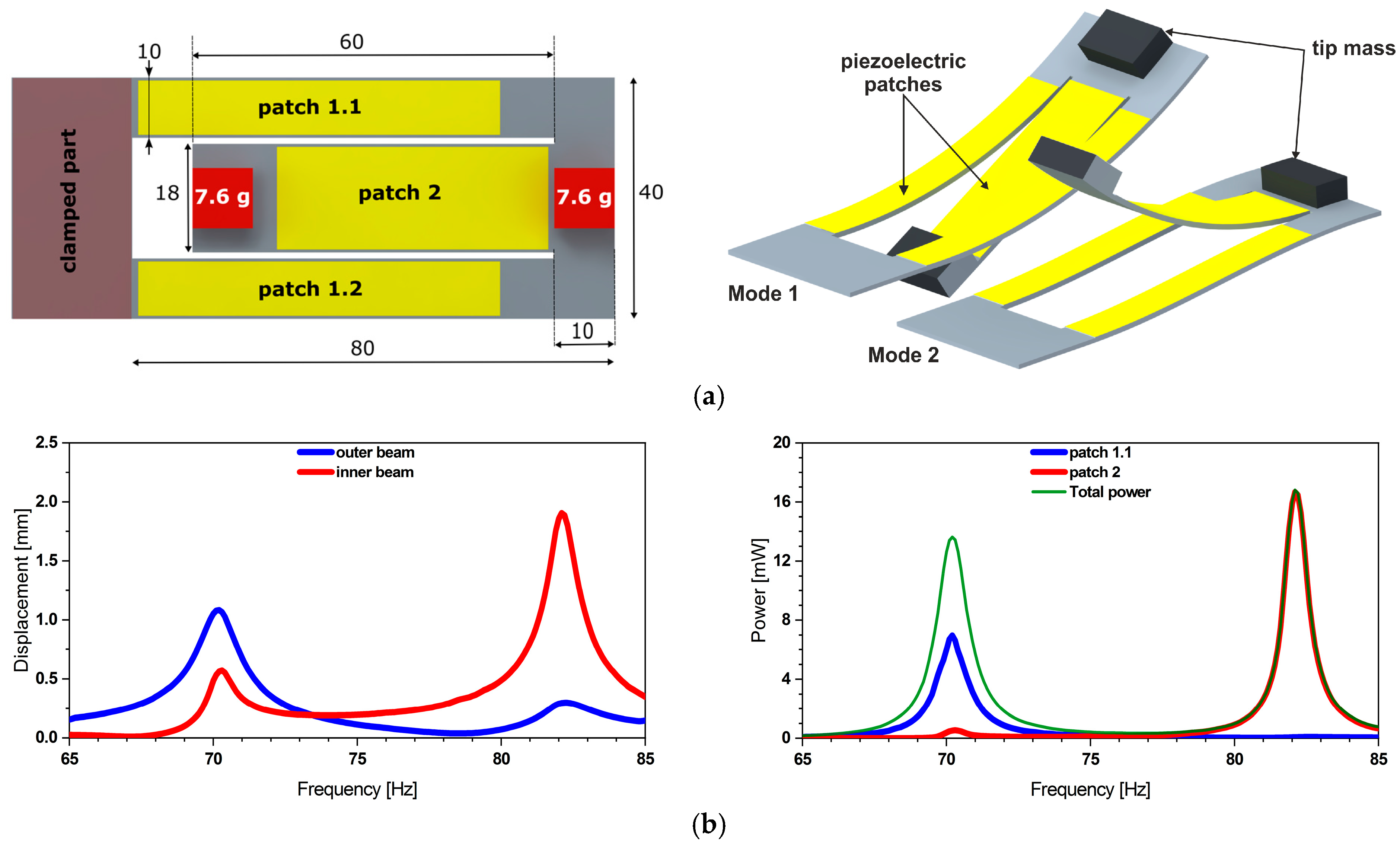
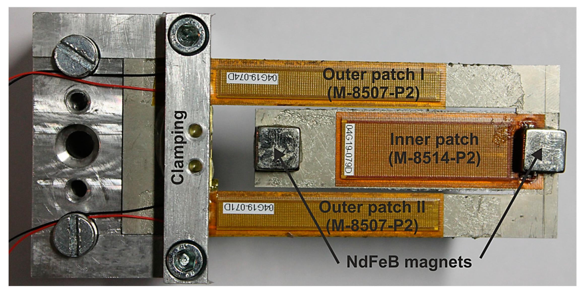
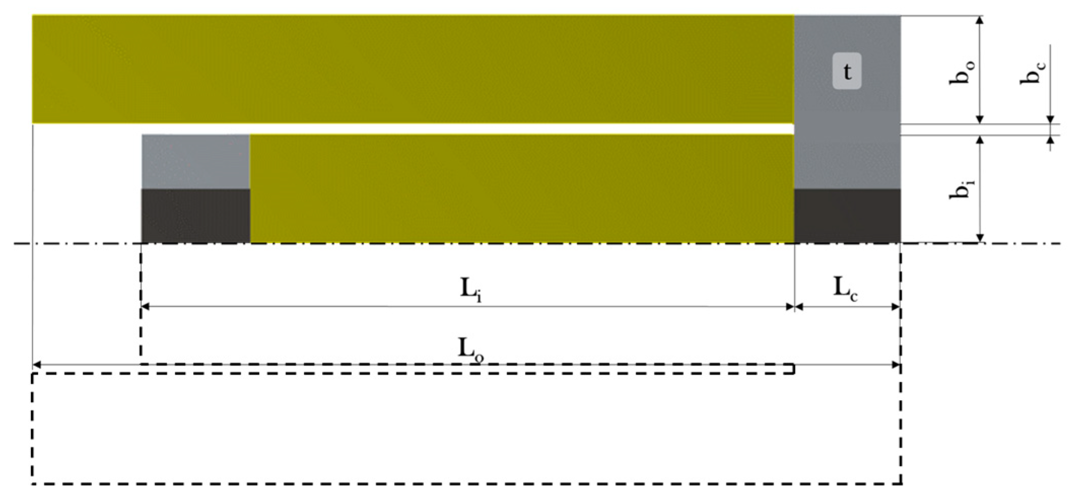
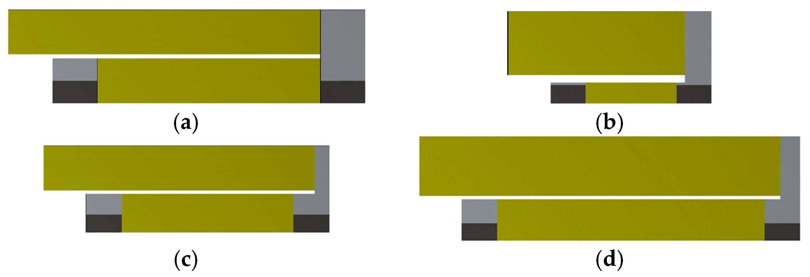
2.1. Design Description
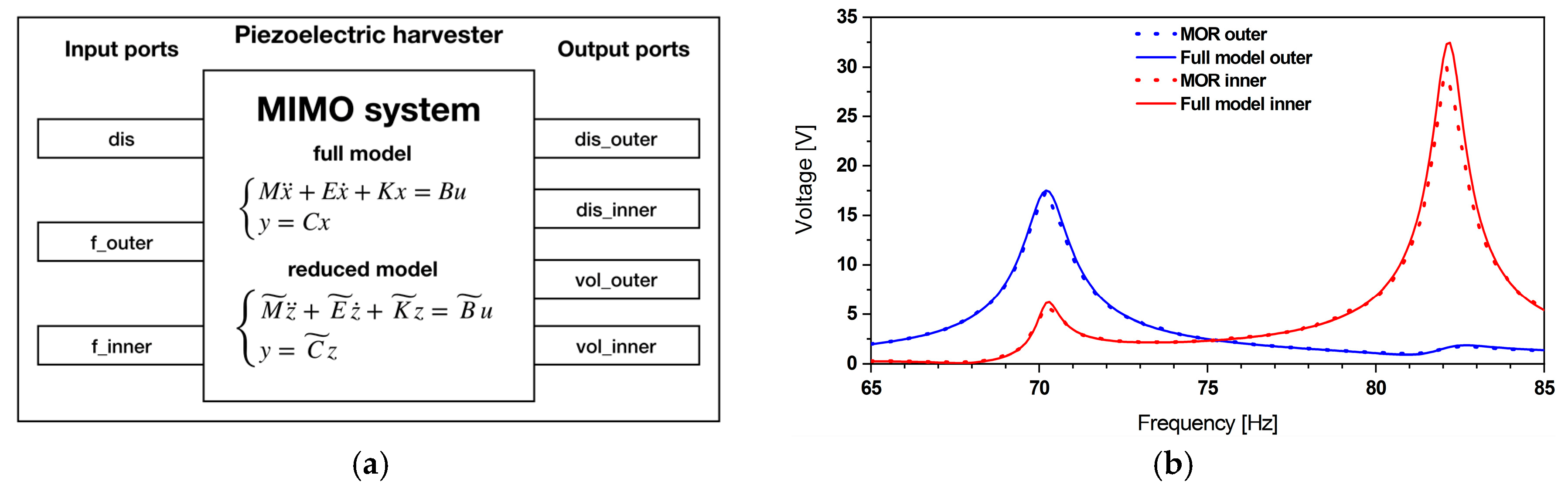
2.2. Reduced Order Model of the Piezoelectric Energy Harvester
Model Order Reduction
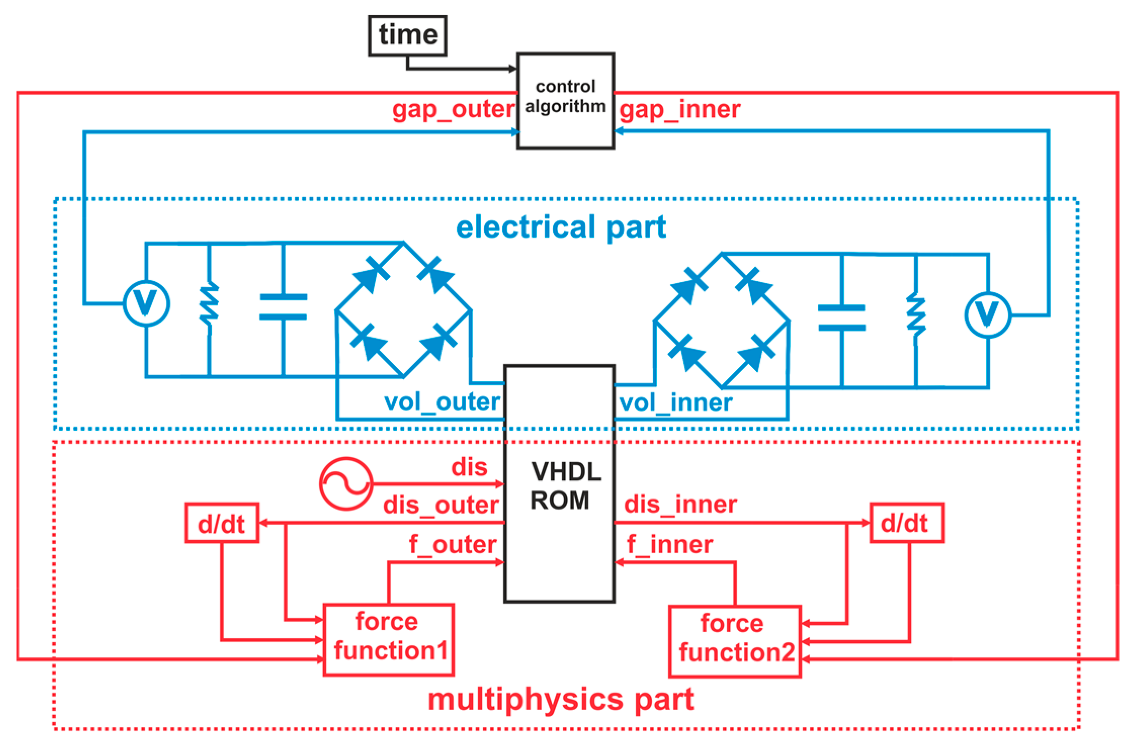
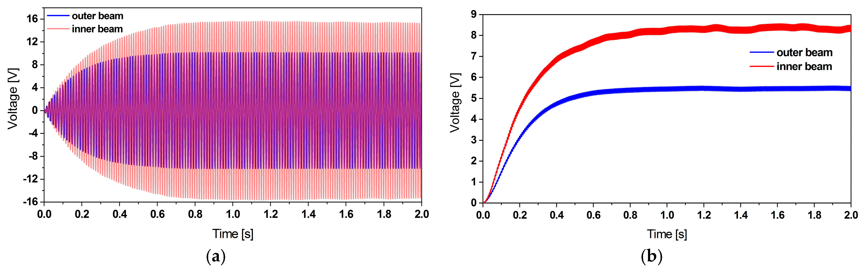
2.3. System-Level Simulation
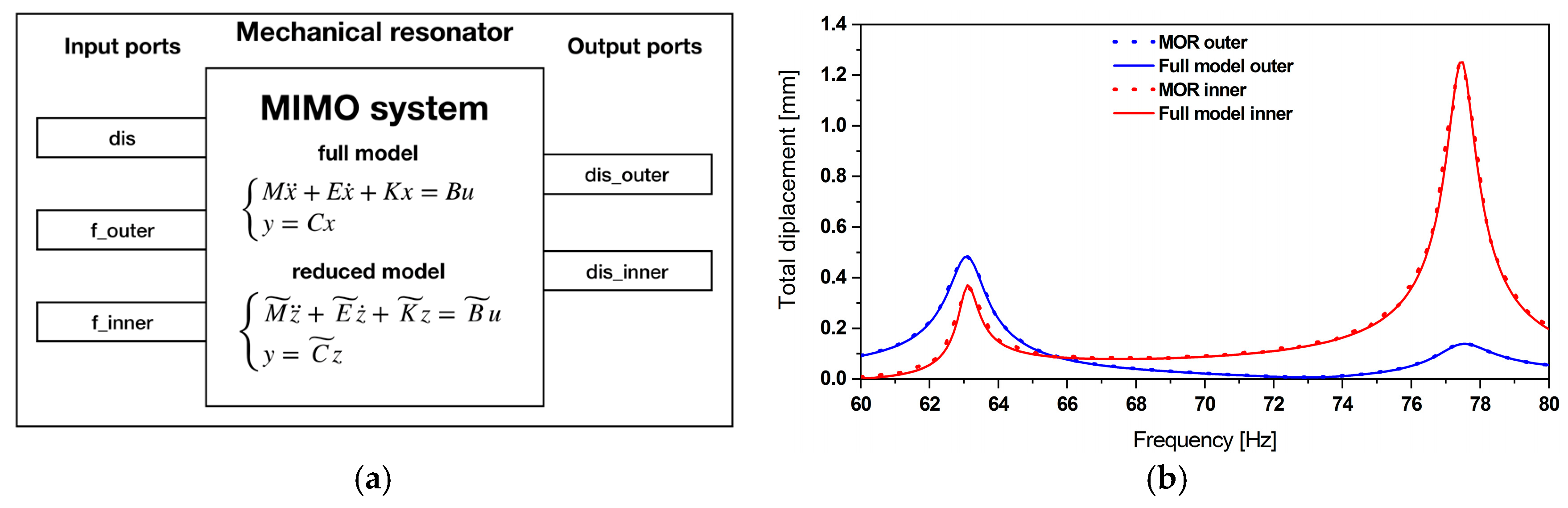
2.3.1. Mechanical Resonator Reduced Order Model
2.3.2. Piezoelectric Energy Harvester Reduced Order Model
2.3.3. Electrical Simulation
Rectification and Filtering
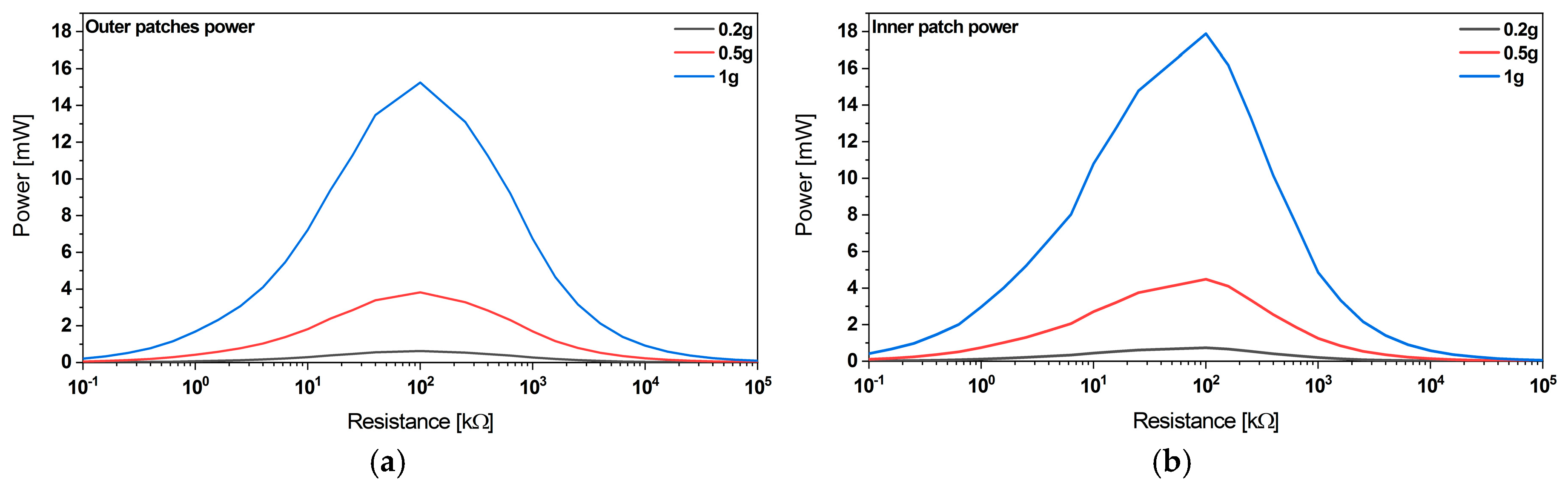
Optimum Load
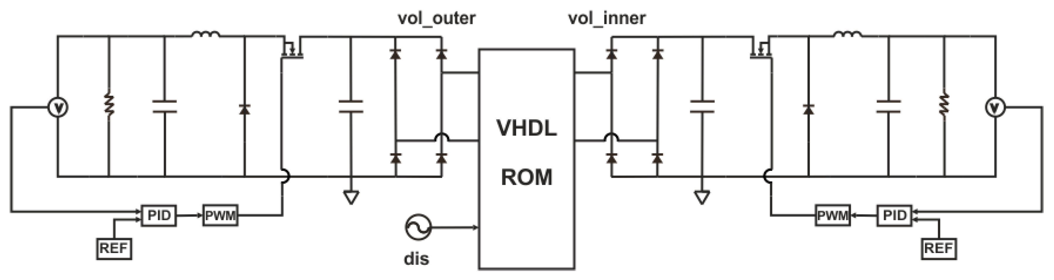
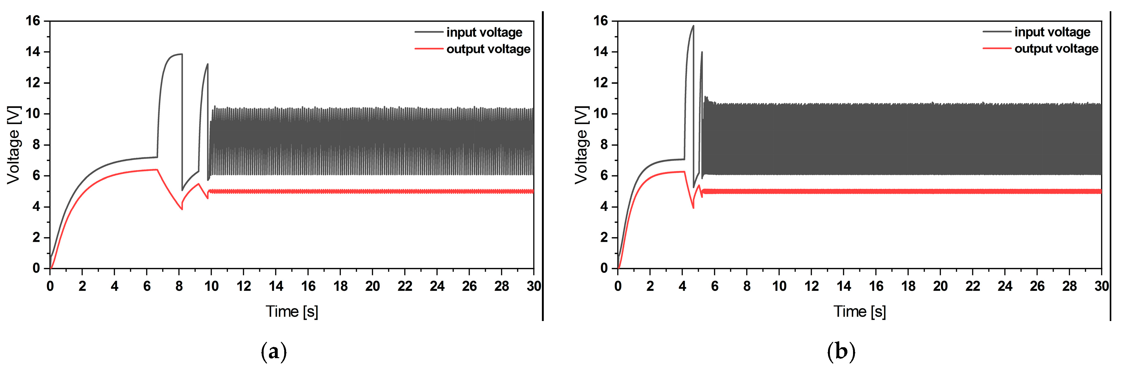
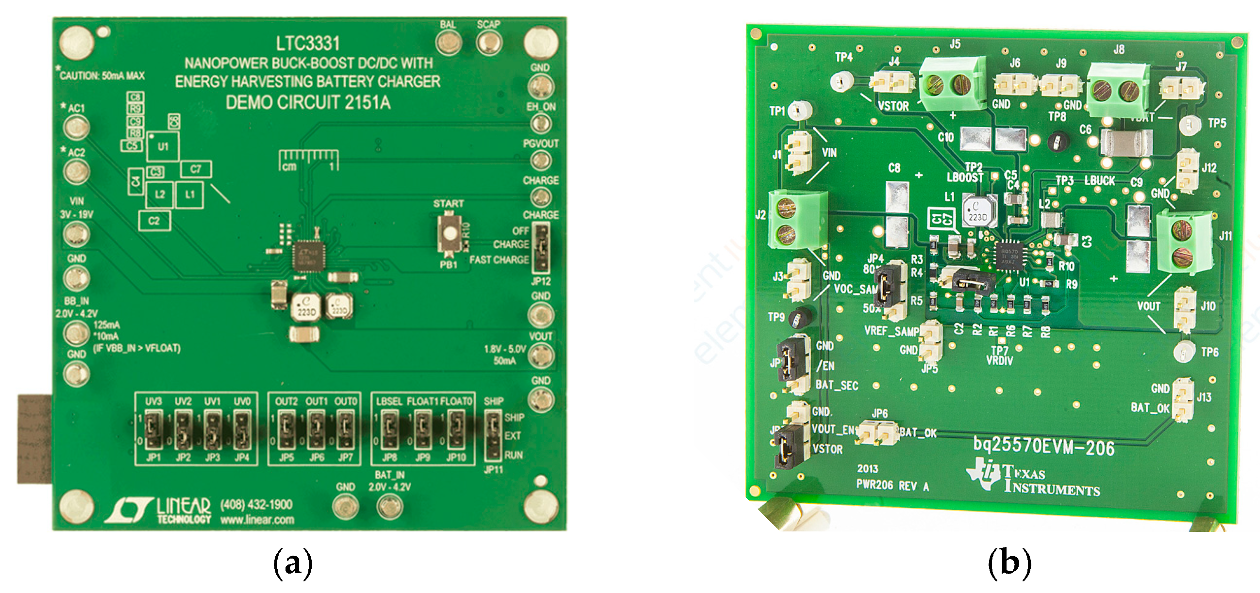
Voltage Regulation
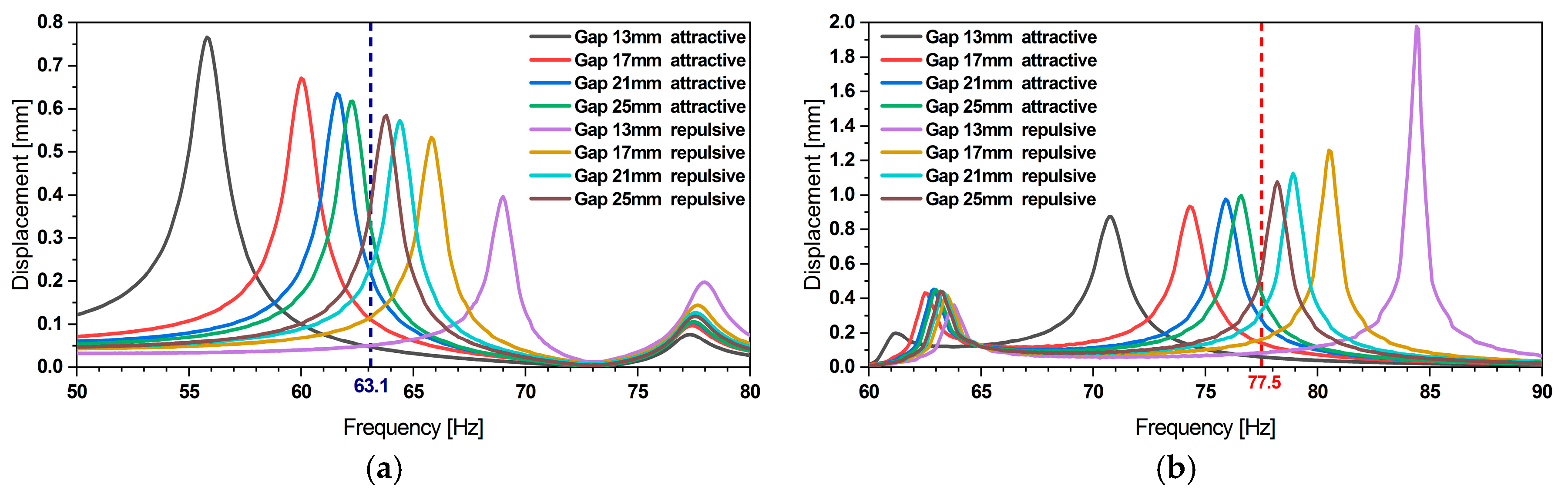
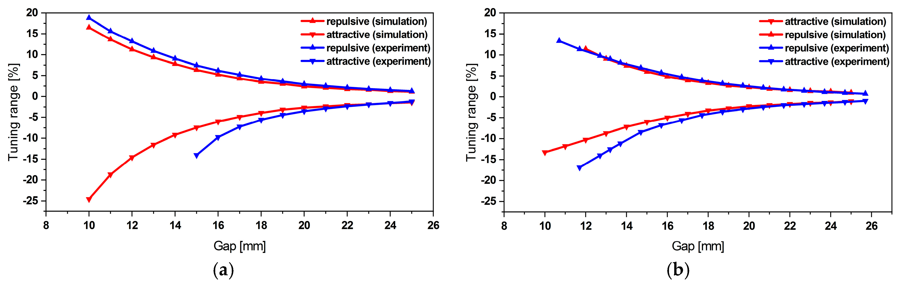
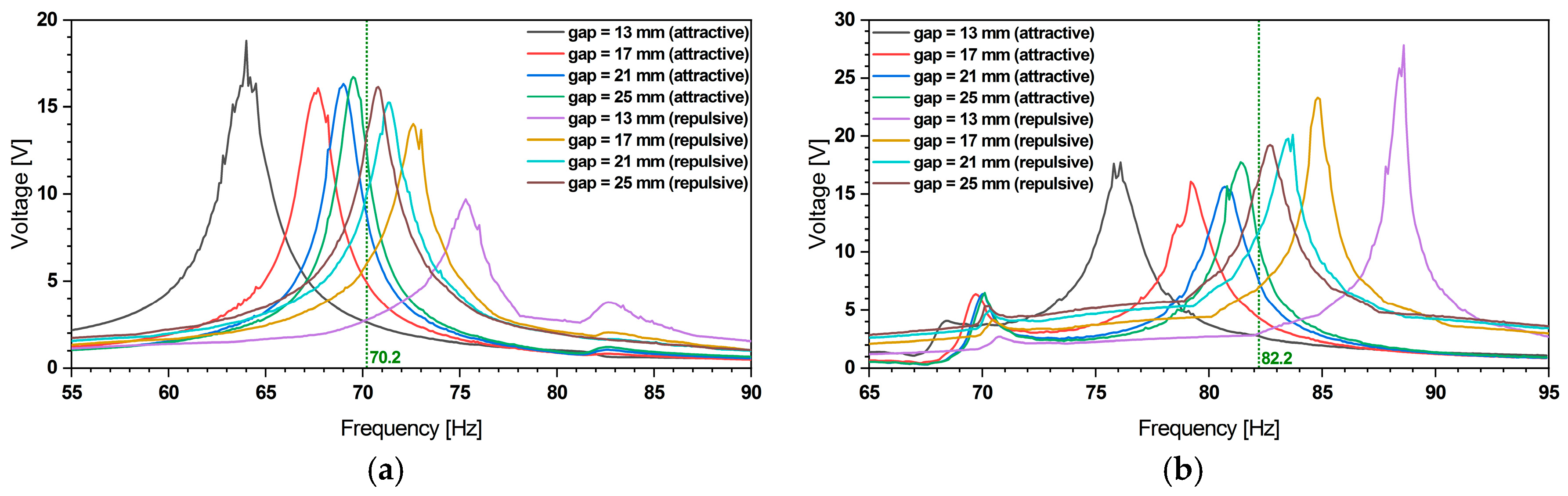
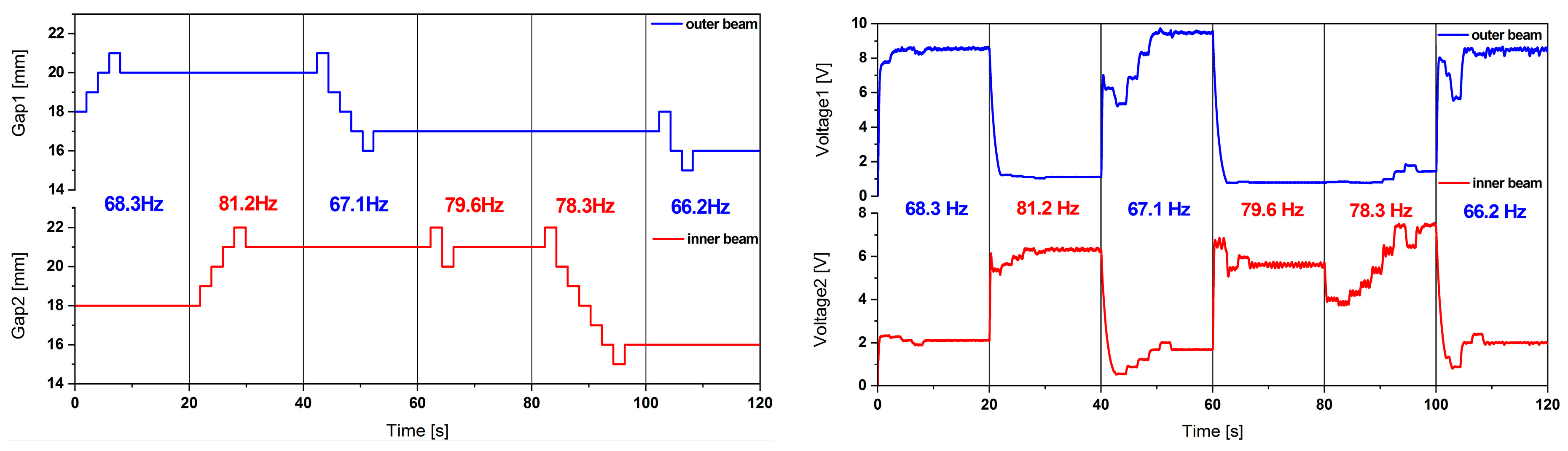
2.3.4. Energy Harvester Frequency Tuning
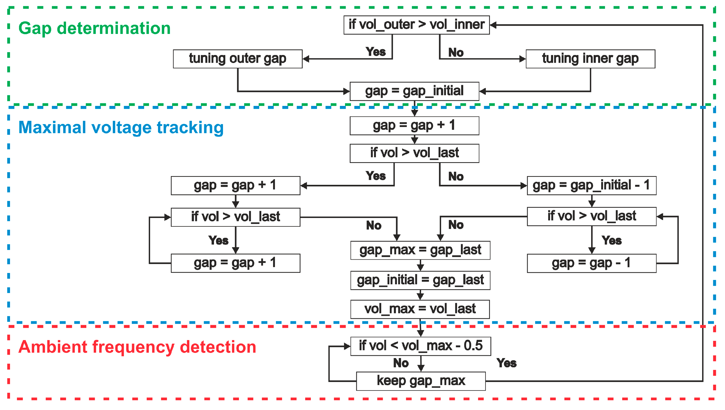
2.3.5. Control Algorithm
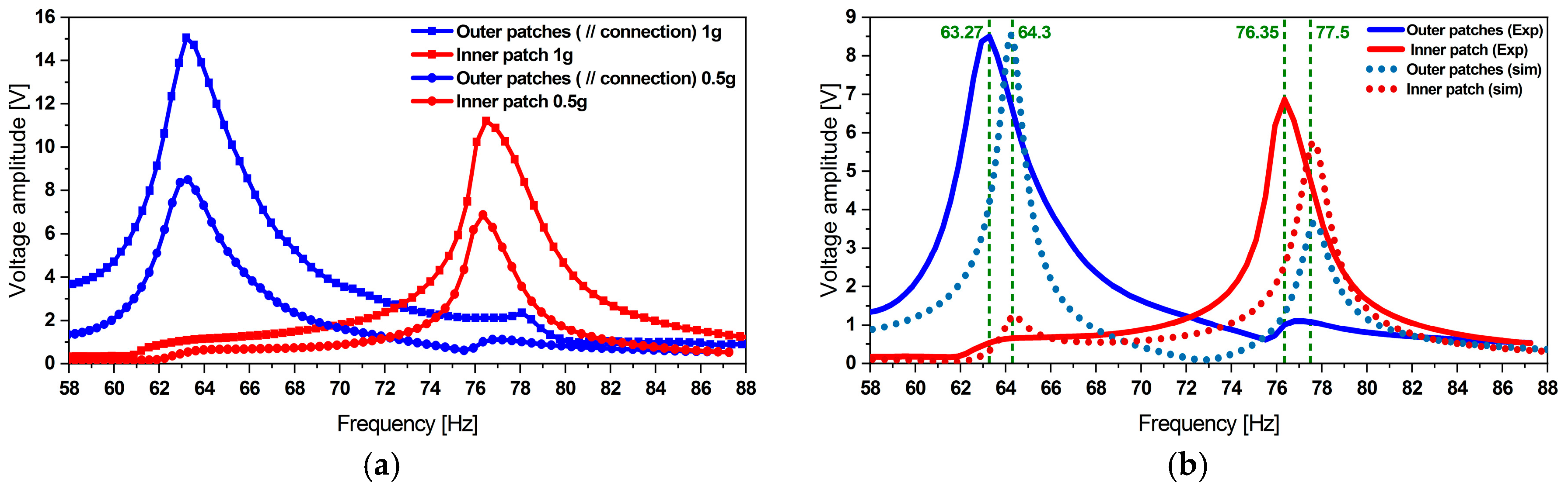
3. Experimental Investigation
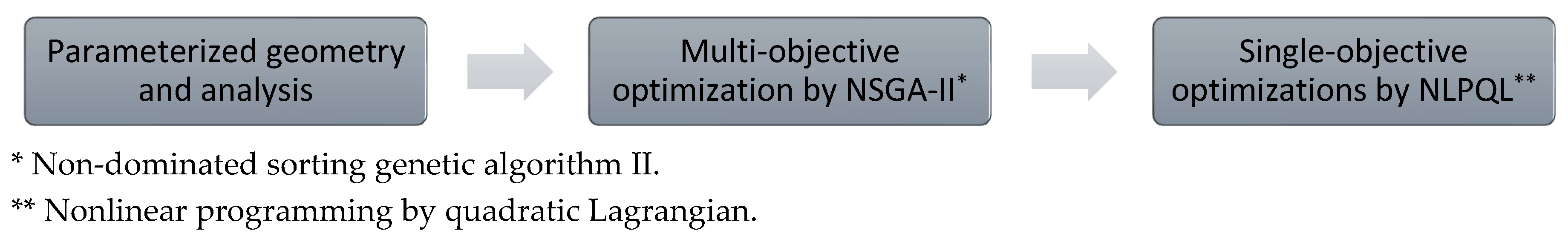
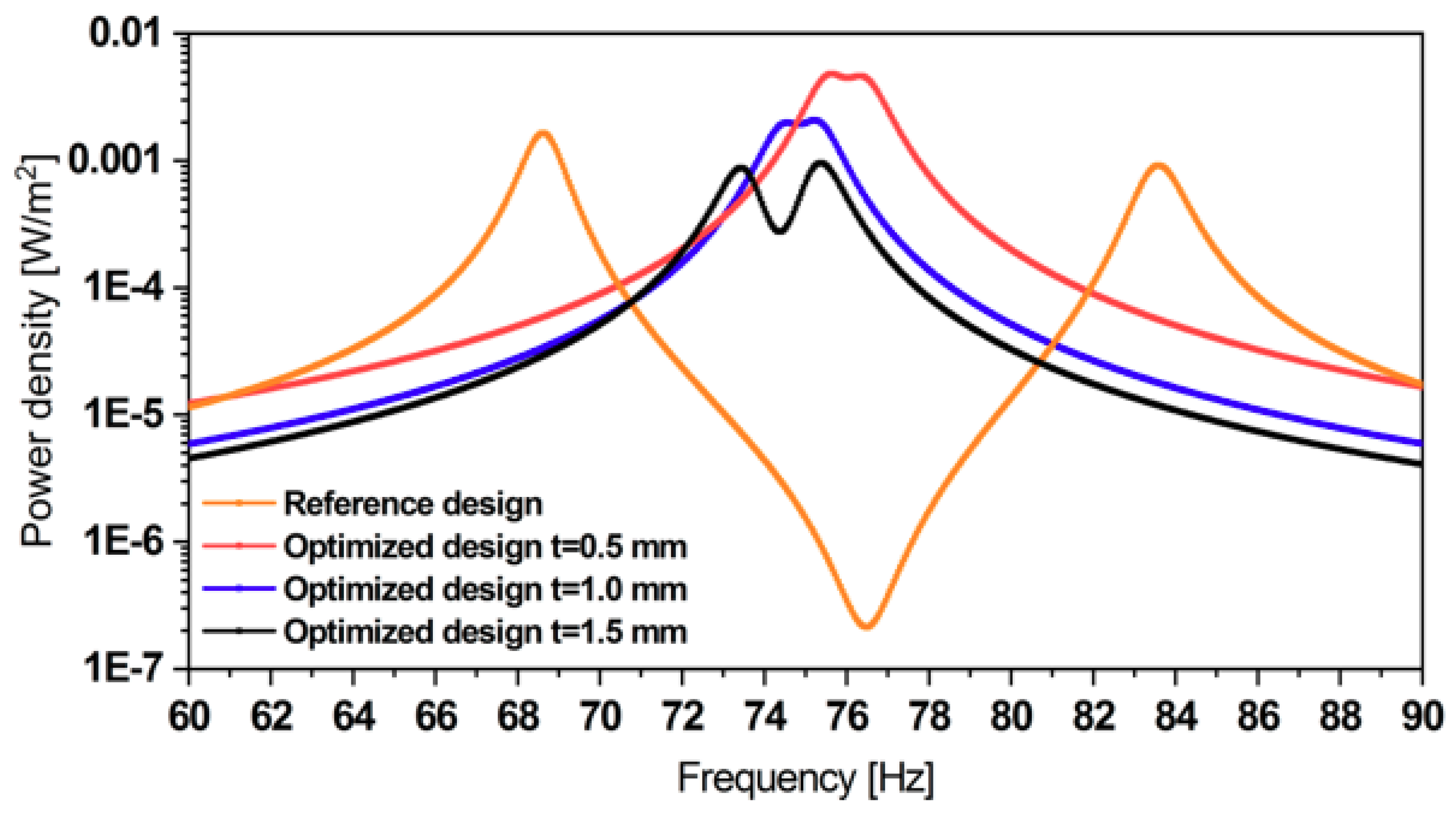
4. Parametric Design Optimization
5. Conclusions
Author Contributions
Funding
Acknowledgments
Conflicts of Interest
References
- Roundy, S.; Leland, E.S.; Baker, J.; Carleton, E.; Reilly, E.; Lai, E.; Otis, B.; Rabaey, J.M.; Sundararajan, V.; Wright, P.K. Improving power output for vibration-based energy scavengers. IEEE Pervasive Comput. 2005, 4, 28–36. [Google Scholar] [CrossRef]
- Erturk, A.; Inman, D.J. A distributed parameter electromechanical model for cantilevered piezoelectric energy harvesters. J. Vib. Acoust. 2008, 130, 41002. [Google Scholar] [CrossRef]
- Liao, Y.; Sodano, H.A. Model of a single mode energy harvester and properties for optimal power generation. Smart Mater. Struct. 2008, 17, 65026. [Google Scholar] [CrossRef]
- Ferrari, M.; Ferrari, V.; Guizzetti, M.; Marioli, D.; Taroni, A. Piezoelectric multifrequency energy converter for power harvesting in autonomous microsystems. Sensors Actuators A Phys. 2008, 142, 329–335. [Google Scholar] [CrossRef]
- Liu, J.-Q.; Fang, H.-B.; Xu, Z.-Y.; Mao, X.-H.; Shen, X.-C.; Chen, D.; Liao, H.; Cai, B.-C. A MEMS-based piezoelectric power generator array for vibration energy harvesting. Microelectron. J. 2008, 39, 802–806. [Google Scholar] [CrossRef]
- Tang, X.; Zuo, L. Enhanced vibration energy harvesting using dual-mass systems. J. Sound Vib. 2011, 330, 5199–5209. [Google Scholar] [CrossRef]
- Tadesse, Y.; Zhang, S.; Priya, S. Multimodal energy harvesting system: Piezoelectric and electromagnetic. J. Intell. Mater. Syst. Struct. 2009, 20, 625–632. [Google Scholar] [CrossRef]
- Wu, H.; Tang, L.; Yang, Y.; Soh, C.K. A novel two-degrees-of-freedom piezoelectric energy harvester. J. Intell. Mater. Syst. Struct. 2013, 24, 357–368. [Google Scholar] [CrossRef]
- Upadrashta, D.; Yang, Y. Trident-shaped multimodal piezoelectric energy harvester. J. Aerosp. Eng. 2018, 31, 4018070. [Google Scholar] [CrossRef]
- Lamprecht, L.; Ehrenpfordt, R.; Lim, C.K.; Zimmermann, A. A 500 Hz-wide kinetic energy harvester: Outperforming macroscopic electrodynamic arrays with piezoelectric arrays. Mech. Syst. Signal Process. 2019, 119, 222–243. [Google Scholar] [CrossRef]
- Qi, S.; Shuttleworth, R.; Olutunde Oyadiji, S.; Wright, J. Design of a multiresonant beam for broadband piezoelectric energy harvesting. Smart Mater. Struct. 2010, 19, 94009. [Google Scholar] [CrossRef]
- Xiao, H.; Wang, X.; John, S. A multi-degree of freedom piezoelectric vibration energy harvester with piezoelectric elements inserted between two nearby oscillators. Mech. Syst. Signal Process. 2015, 6869, 138–154. [Google Scholar] [CrossRef]
- Xiao, Z.; Yang, T.Q.; Dong, Y.; Wang, X.C. Energy harvester array using piezoelectric circular diaphragm for broadband vibration. Appl. Phys. Lett. 2014, 104, 223904. [Google Scholar] [CrossRef]
- Ramírez, J.M.; Gatti, C.D.; Machado, S.P.; Febbo, M. A piezoelectric energy harvester for rotating environment using a linked E-shape multi-beam. Extreme Mech. Lett. 2019, 27, 8–19. [Google Scholar] [CrossRef]
- Challa, V.R.; Prasad, M.G.; Shi, Y.; Fisher, F.T. A vibration energy harvesting device with bidirectional resonance frequency tunability. Smart Mater. Struct. 2008, 17, 15035. [Google Scholar] [CrossRef]
- Spreemann, D.; Manoli, Y. Electromagnetic Vibration Energy Harvesting Devices; Springer: Dordrecht, The Netherlands, 2012. [Google Scholar]
- Xu, M.; Li, X. Stochastic averaging for bistable vibration energy harvesting system. Inter. J. Mech. Sci. 2018, 141, 206–212. [Google Scholar] [CrossRef]
- Daqaq, M.F. On intentional introduction of stiffness nonlinearities for energy harvesting under white Gaussian excitations. Nonlinear Dyn. 2012, 69, 1063–1079. [Google Scholar] [CrossRef]
- Stanton, S.C.; McGehee, C.C.; Mann, B.P. Nonlinear dynamics for broadband energy harvesting: Investigation of a bistable piezoelectric inertial generator. Phys. D Nonlinear Phenom. 2010, 239, 640–653. [Google Scholar] [CrossRef]
- Zhou, S.; Zuo, L. Nonlinear dynamic analysis of asymmetric tristable energy harvesters for enhanced energy harvesting. Commun. Nonlinear Sci. Numer. Simul. 2018, 61, 271–284. [Google Scholar] [CrossRef]
- Abdelkefi, A.; Barsallo, N. Nonlinear analysis and power improvement of broadband low-frequency piezomagnetoelastic energy harvesters. Nonlinear Dyn 2016, 83, 41–56. [Google Scholar] [CrossRef]
- Lai, S.-K.; Wang, C.; Zhang, L.-H. A nonlinear multi-stable piezomagnetoelastic harvester array for low-intensity, low-frequency, and broadband vibrations. Mech. Syst. Signal Process. 2019, 122, 87–102. [Google Scholar] [CrossRef]
- Hoffmann, D.; Folkmer, B.; Manoli, Y. Experimental Analysis of a Coupled Energy Harvesting System with Monostable and Bistable Configuration. J. Phys. Conf. Ser. 2014, 557, 12134. [Google Scholar] [CrossRef] [Green Version]
- Hoffmann, D.; Willmann, A.; Hehn, T.; Folkmer, B.; Manoli, Y. A self-adaptive energy harvesting system. Smart Mater. Struct. 2016, 25, 35013. [Google Scholar] [CrossRef]
- Fu, H.; Yeatman, E.M. Broadband Rotational Energy Harvesting with Non-linear Oscillator and Piezoelectric Transduction. J. Phys. Conf. Ser. 2016, 773, 12008. [Google Scholar] [CrossRef]
- Fu, H.; Yeatman, E.M. Rotational energy harvesting using bi-stability and frequency up-conversion for low-power sensing applications: Theoretical modelling and experimental validation. Mech. Syst. Signal Process. 2018. [Google Scholar] [CrossRef]
- Challa, V.R.; Prasad, M.G.; Fisher, F.T. Towards an autonomous self-tuning vibration energy harvesting device for wireless sensor network applications. Smart Mater. Struct. 2011, 20, 25004. [Google Scholar] [CrossRef] [Green Version]
- Neiss, S.; Goldschmidtboeing, F.; Kroener, M.; Woias, P. Analytical model for nonlinear piezoelectric energy harvesting devices. Smart Mater. Struct. 2014, 23, 105031. [Google Scholar] [CrossRef]
- Neiss, S.; Goldschmidtboeing, F.; Kroener, M.; Woias, P. Tunable nonlinear piezoelectric vibration harvester. J. Phys. Conf. Ser. 2014, 557, 12113. [Google Scholar] [CrossRef] [Green Version]
- Nammari, A.; Caskey, L.; Negrete, J.; Bardaweel, H. Fabrication and characterization of non-resonant magneto-mechanical low-frequency vibration energy harvester. Mech. Syst. Signal Process. 2018, 102, 298–311. [Google Scholar] [CrossRef]
- Bouhedma, S.; Hohlfeld, D. Frequency tunable piezoelectric energy harvester with segmented electrodes for improved power generation. In Proceedings of the MikroSystemTechnik 2017, Munich, Germany, 23–25 October 2017. [Google Scholar]
- Bouhedma, S.; Hartwig, H.; Hohlfeld, D. Modeling and Characterization of a Tunable Dual-Frequency Piezoelectric Energy Harvester. In Proceedings of the 2018 IEEE/ASME International Conference on Advanced Intelligent Mechatronics (AIM), Auckland, New Zealand, 9–12 July 2018; pp. 1378–1383. [Google Scholar]
- Bouhedma, S.; Zheng, Y.; Hohlfeld, D. Simulation and Characterization of a Nonlinear Dual-Frequency Piezoelectric Energy Harvester. Proceedings 2018, 2, 908. [Google Scholar] [CrossRef] [Green Version]
- Bouhedma, S.; Zheng, Y.; Lange, F.; Hohlfeld, D. Magnetic frequency tuning of a multimodal vibration energy harvester. Sensors 2019, 19, 1149. [Google Scholar] [CrossRef] [PubMed] [Green Version]
- Eichhorn, C.; Tchagsim, R.; Wilhelm, N.; Biancuzzi, G.; Woias, P. An energy-autonomous self-tunable piezoelectric vibration energy harvesting system. In Proceedings of the IEEE 24th International Conference on Micro Electro Mechanical Systems (MEMS), Cancun, Mexico, 23–27 January 2011. [Google Scholar]
- Lumentut, M.F.; Howard, I.M. Electromechanical analysis of an adaptive piezoelectric energy harvester controlled by two segmented electrodes with shunt circuit networks. Acta Mech 2017, 228, 1321–1341. [Google Scholar] [CrossRef] [Green Version]
- Zhang, H.; Afzalul, K. Design and analysis of a connected broadband multi-piezoelectric-bimorph- beam energy harvester. IEEE Trans. Ultrason. Ferroelectr. Freq. Control 2014, 61, 1016–1023. [Google Scholar] [CrossRef] [PubMed]
- Freund, R.W. Krylov-subspace methods for reduced-order modeling in circuit simulation. J. Comput. Appl. Math. 2000, 123, 395–421. [Google Scholar] [CrossRef] [Green Version]
- Gugercin, S.; Stykel, T.; Wyatt, S. Model Reduction of Descriptor Systems by Interpolatory Projection Methods. SIAM J. Sci. Comput. 2013, 35, B1010–B1033. [Google Scholar] [CrossRef] [Green Version]
- Beattie, C.A.; Gugercin, S. Model Reduction by Rational Interpolation. In Model Reduction and Approximation: Theory and Algorithm; Benner, P., Cohen, A., Ohlberger, M., Willcox, K., Eds.; Society for Industrial and Applied Mathematics: University City, PA, USA, 2014; pp. 297–334. [Google Scholar]
- Salimbahrami, B. Structure Preserving Order Reduction of Large Scale Second Order Models. Ph.D. Thesis, Fakultät für Maschinenwesen, Technischen Universität München, Munich, Germany, 2005. [Google Scholar]
- Bai, Z.; Su, Y. Dimension Reduction of Large-Scale Second-Order Dynamical Systems via a Second-Order Arnoldi Method. SIAM J. Sci. Comput. 2005, 26, 1692–1709. [Google Scholar] [CrossRef] [Green Version]
- Chen, C.-C.; Kuo, C.-W.; Yang, Y.-J. Generating Passive Compact Models for Piezoelectric Devices. IEEE Trans. Comput.-Aided Des. Integr. Circuits Syst. 2011, 30, 464–467. [Google Scholar] [CrossRef]
- Aftag, T.; Bechtold, T.; Hohlfeld, D.; Rudnyi, E.B.; Korvink, J.G. New Modeling Approach for Micro Energy Harvesting Systems Based on Model Order Reduction Enabling Truly System-level Simulation. In Proceedings of the 23rd Micromechanics and Microsystems Europe Workshop, Ilmenau, Germany, 9–12 September 2012. [Google Scholar]
- Kurch, M. Entwicklung einer Simulationsumgebung für die Auslegung piezoelektrischer Energy Harvester. Ph.D. Thesis, Technischen Universität Darmstadt, Darmstadt, Germany, 2014. [Google Scholar]
- Kudryavtsev, M.; Rudnyi, E.B.; Korvink, J.G.; Hohlfeld, D.; Bechtold, T. Computationally efficient and stable order reduction methods for a large-scale model of MEMS piezoelectric energy harvester. Microelectron. Reliab. 2015, 55, 747–757. [Google Scholar] [CrossRef]
- Hu, S.; Yuan, C.; Castagnotto, A.; Lohmann, B.; Bouhedma, S.; Hohlfeld, D.; Bechtold, T. Stable reduced order modeling of piezoelectric energy harvesting modules using implicit Schur complement. Microelectron. Reliab. 2018, 85, 148–155. [Google Scholar] [CrossRef]
- Hu, S.; Yuan, C.; Bechtold, T. Quasi-Schur Transformation for the Stable Compact Modeling of Piezoelectric Energy Harvester Devices. In Proceedings of the 12th International Conference on Science Computing in Electrical Engineering (SCEE), Taormina, Sicily, Italy, 23–27 September 2018. [Google Scholar]


| Material Properties | Value |
|---|---|
| Mass density (kg/m3) | 5440 |
| Tensile modulus, E1 (rod direction) (GPa) | 30.34 |
| Tensile modulus, E1 (electrode direction) (GPa) | 15.86 |
| Poisson’s ratio, v12 | 0.31 |
| Poisson’s ratio, v21 | 0.16 |
| Shear modulus, G12 (GPa) | 5.515 |
| d33 (rod direction) (pC/N) | 400 |
| d31 (electrode direction) (pC/N) | −170 |
| Patch | f (Hz) | Vout (V) | Iout (μA) | R (kΩ) | Pout (μW) |
|---|---|---|---|---|---|
| Outer (// connection) | 65.27 | 2.615 | 125.0 | 21.00 | 653.8 |
| Inner | 1.0 | 0.256 | 21.00 | 0.512 | |
| Outer (// connection) | 78.35 | 0.381 | 18.20 | 22.00 | 13.87 |
| Inner | 2.305 | 105.1 | 22.00 | 484.5 |
| Board Type | Vin (V) | Iin (μA) | R (kΩ) | Vout (V) | Iout (μA) | Efficiency (%) |
|---|---|---|---|---|---|---|
| bq25570EVM-206 | 3.73 | 134.5 | 13.0 | 1.8 | 137.5 | 49.4 |
| 2151A | 4.42 | 106.0 | 14.5 | 1.8 | 124.5 | 47.8 |
| Parameter | Reference Value (mm) | Lower Bound (mm) | Upper Bound (mm) |
|---|---|---|---|
| 80 | 40 | 120 | |
| 10 | 5.0 | 15.0 | |
| 10 | 5.0 | 15.0 | |
| 1.0 | 0.5 | 1.50 | |
| 60 | 23 | 113 | |
| 9.0 | 5.0 | 15.0 | |
| t 1 | 1.0 | 0.5 | 1.50 |
© 2020 by the authors. Licensee MDPI, Basel, Switzerland. This article is an open access article distributed under the terms and conditions of the Creative Commons Attribution (CC BY) license (http://creativecommons.org/licenses/by/4.0/).
Share and Cite
Bouhedma, S.; Rao, Y.; Schütz, A.; Yuan, C.; Hu, S.; Lange, F.; Bechtold, T.; Hohlfeld, D. System-Level Model and Simulation of a Frequency-Tunable Vibration Energy Harvester. Micromachines 2020, 11, 91. https://doi.org/10.3390/mi11010091
Bouhedma S, Rao Y, Schütz A, Yuan C, Hu S, Lange F, Bechtold T, Hohlfeld D. System-Level Model and Simulation of a Frequency-Tunable Vibration Energy Harvester. Micromachines. 2020; 11(1):91. https://doi.org/10.3390/mi11010091
Chicago/Turabian StyleBouhedma, Sofiane, Yongchen Rao, Arwed Schütz, Chengdong Yuan, Siyang Hu, Fred Lange, Tamara Bechtold, and Dennis Hohlfeld. 2020. "System-Level Model and Simulation of a Frequency-Tunable Vibration Energy Harvester" Micromachines 11, no. 1: 91. https://doi.org/10.3390/mi11010091