Microfluidics Mediated Production of Foams for Biomedical Applications

Abstract
: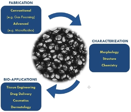
1. Introduction
2. Foam Fabrication Techniques
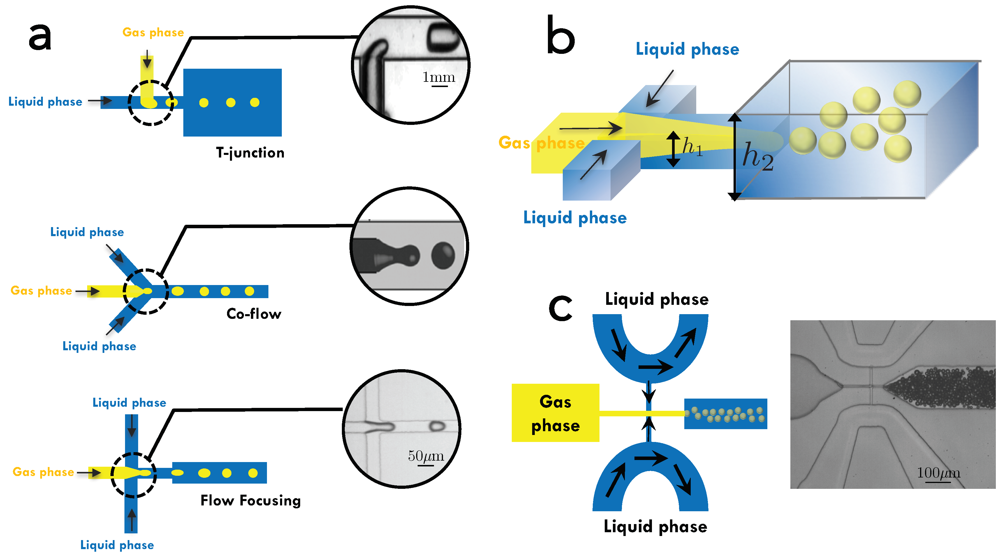
3. The Use of Microfluidics for Production of Foams
3.1. Bubble Production Using Commonly-Used Microfluidic Geometries
3.2. Formation of Liquid Foam Structures from Bubbles
3.3. Formation of Solid Foam Structures
4. Methods of Characterization of Liquid and Solid Foams
5. Foams for Biomedical Applications
6. Conclusions
Author Contributions
Funding
Acknowledgments
Conflicts of Interest
References
- Langevin, D. Aqueous foams and foam films stabilised by surfactants. Comptes Rendus Mec. 2017, 345, 47–55. [Google Scholar] [CrossRef] [Green Version]
- Fameau, A.L.; Saint-Jalmes, A.; Cousin, F.; Houssou, B.H.; Novales, B.; Navailles, L.; Nallet, F.; Gaillard, D. Smart Foams: Switching Reversibly between Ultrastable and Unstable Foams. Angew. Chem. Int. Ed. 2011, 50, 8264–8269. [Google Scholar] [CrossRef] [PubMed] [Green Version]
- Osei-bonsu, K.; Grassia, P.; Shokri, N. Relationship between bulk foam stability, surfactant formulation and oil displacement efficiency in porous media. Fuel 2017, 203, 403–410. [Google Scholar] [CrossRef]
- Korat, L.; Ducman, V. The influence of the stabilizing agent SDS on porosity development in alkali-activated fly-ash based foams. Cem. Concr. Compos. 2017, 80, 168–174. [Google Scholar] [CrossRef]
- Wang, D.; Hou, Q.; Luo, Y.; Zhu, Y.; Fan, H. Stability Comparison Between Particles-Stabilized Foams and Polymer-Stabilized Foams. J. Dispers. Sci. Technol. 2014, 36, 268–273. [Google Scholar]
- Rybak, O. Some aspects of the formation of emulsions and foams in food industry. Ukr. J. Food Sci. 2013, 1, 41–49. [Google Scholar]
- Arzhavitina, A.; Steckel, H. Foams for pharmaceutical and cosmetic application. Int. J. Pharm. 2010, 394, 1–17. [Google Scholar]
- Tamarkin, D. Foam: A unique topical drug delivery system. Adv. Dermatol. Sci. 2017, 6, 189–206. [Google Scholar] [CrossRef]
- Purdon, C.H.; Haigh, J.M.; Surber, C.; Smith, E.W. Foam Drug Delivery in Dermatology. Am. J. Drug Deliv. 2003, 1, 71–75. [Google Scholar] [CrossRef]
- Shemer, A.; Sakka, N.; Tamarkin, D. Betamethasone valerate foam: A look at the clinical data. Clin. Investig. 2014, 4, 259–267. [Google Scholar] [CrossRef]
- Clark, W.E. Firefighting Principles and Practices; PennWell Books: Saddle Brook, NJ, USA, 1991. [Google Scholar]
- Quennouz, N.; Ryba, M.; Argilier, J.F.; Herzhaft, B.; Peysson, Y.; Pannacci, N. Microfluidic Study of Foams Flow for Enhanced Oil Recovery (EOR). Oil Gas Sci. Technol. Rev. IFP Energies Nouv. 2014, 69, 457–466. [Google Scholar] [CrossRef] [Green Version]
- Kamble, M.S.; Sutar, S.P.; Shinde, S.A.; Chaudhuri, P.D.; Bhosale, A.V.; Nanjwade, B.K. Development of Pharmaceutical Foam Based Topical Drug Delivery System. J. Biopharm. Sci. 2017, 1, 5–9. [Google Scholar]
- Makadia, H.K.; Siegel, S.J. Poly Lactic-co-Glycolic Acid (PLGA) as Biodegradable Controlled Drug Delivery Carrier. Polymers 2011, 3, 1377–1397. [Google Scholar] [CrossRef] [PubMed]
- Shinde, N.G.; Aloorkar, N.H.; Bangar, B.; Deshmukh, S.M.; Shirke, M.V.; Birudev, B.K. Pharmaceutical Foam Drug Delivery System: General Considerations. Indo Am. J. Pharm. Res. 2013, 3, 1322–1327. [Google Scholar]
- Tan, M.X.L.; Danquah, M.K. Drug and Protein Encapsulation by Emulsification: Technology Enhancement Using Foam Formulations. Chem. Eng. Technol. 2012, 35, 618–626. [Google Scholar]
- Xu, Y.; Kim, C.S.; Saylor, D.M.; Koo, D. Polymer degradation and drug delivery in PLGA-based drug-polymer applications: A review of experiments and theories. J. Biomed. Mater. Res. Part B Appl. Biomater. 2017, 105B, 1692–1716. [Google Scholar]
- Zhao, Y.; Jones, S.A.; Brown, M.B. Dynamic foams in topical drug delivery. J. Pharm. Pharmacol. 2010, 62, 678–684. [Google Scholar] [CrossRef]
- Seymour, R.B.; Kauffman, G.B. Polyurethanes: A Class of Modern Versatile Materials. J. Chem. Educ. 1992, 61, 909. [Google Scholar]
- Yam, K.L. (Ed.) The Wiley Encyclopedia of Packaging Technology, 3rd ed.; John Wiley and Sons, Inc.: Hoboken, NJ, USA, 2009. [Google Scholar]
- Netti, P.A. Biomedical Foams for Tissue Engineering Applications; Elsevier: Amsterdam, The Netherlands, 2014. [Google Scholar]
- Dhandayuthapani, B.; Yoshida, Y.; Maekawa, T.; Kumar, D.S. Polymeric Scaffolds in Tissue Engineering Application: A Review. Int. J. Polym. Sci. 2011, 2011, 290602. [Google Scholar] [CrossRef]
- Singh, R.; Lee, P.D.; Dashwood, J.; Lindley, T.C. Titanium foams for biomedical applications: A review. Mater. Technol. 2010, 25, 127–136. [Google Scholar] [CrossRef]
- Langer, R.; Peppas, N.A. Advances in Biomaterials, Drug Delivery, and Bionanotechnology. AlChE J. 2003, 49, 2990–3006. [Google Scholar] [CrossRef]
- Duraiswamy, S.; Khan, S.A. Plasmonic Nanoshell Synthesis in Microfluidic Composite Foams. Nano Lett. 2010, 10, 3757–3763. [Google Scholar] [CrossRef] [PubMed]
- Schoichet, M. Polymer Scaffolds for Biomaterials Applications. Macromolecules 2010, 43, 581–591. [Google Scholar] [CrossRef]
- Aram, E.; Mehdipour-Ataei, S. A Review on the Microfluidic and Nanoporous Polymeric Foams: Preparation and Properties. Int. J. Polyemric Mater. Polymeric Biomater. 2015, 65, 358–375. [Google Scholar] [CrossRef]
- Janik, H.; Marzec, M. A review: Fabrication of porous polyurethane scaffolds. Mater. Sci. Eng. C 2015, 49, 586–591. [Google Scholar] [CrossRef]
- Stubenrauch, C.; Menner, A.; Bismarck, A.; Drenckhan, W. Emulsion and Foam Templating - Promising Routes to Tailor-Made Porous Polymers. Angew. Chem. Int. Ed. 2018, 57, 10024–10032. [Google Scholar] [CrossRef]
- Montanaro, L.; Jorand, Y.; Fantozzi, G.; Negro, A. Ceramic foams by powder processing. J. Eur. Ceram. Soc. 1998, 18, 1339–1350. [Google Scholar] [CrossRef]
- Holter, W.; Echterhoff, M.; Blomer, A.; Verfurden, H. The management of amputations of the leg using a new rigid foam plaster for prosthetic fitting. Int. Orthop. 1980, 4, 73–77. [Google Scholar] [CrossRef]
- Guarino, V.; Causa, F.; Netti, P.A.; Ciapetti, G.; Pagani, S.; Martini, D.; Baldini, N.; Ambrosio, L. The Role of Hydroxyapatite as Solid Signal on Performance of PCL Porous Scaffolds for Bone Tissue Regeneration. J. Biomed. Mater. Res. Part B Appl. Biomater. 2008, 86, 548–557. [Google Scholar] [CrossRef]
- Niinomi, M. Recent research and development in Titanium alloys for biomedical applications and healthcare goods. Sci. Technol. Adv. Mater. 2003, 4, 445. [Google Scholar] [CrossRef] [Green Version]
- Wang, H.; Li, T.T.; Wu, L.; Lou, C.W.; Lin, J.H. Multifunctional, Polyurethane-Based Foam Composites Reinforced by a Fabric Structure: Preparation, Mechanical, Acoustic, and EMI Shielding Properties. Materials 2018, 11, 2085. [Google Scholar] [CrossRef] [Green Version]
- Drenckhan, W.; Saint-Jalmes, A. The science of foaming. Adv. Colloids Interface Sci. 2015, 222, 228–259. [Google Scholar] [CrossRef]
- Andrieux, S.; Quell, A.; Stubenrauch, C.; Drenckhan, W. Liquid foam templating—A route to tailor-mad epolymer foams. Adv. Colloids Interface Sci. 2018, 256, 276–290. [Google Scholar] [CrossRef] [PubMed]
- Temenoff, J.S.; Mikos, A.G. Review: Tissue engineering for regeneration of articular cartilage. Biomaterials 2000, 21, 431–440. [Google Scholar] [CrossRef]
- Costantini, M.; Colosi, C.; Jaroszewicz, J.; Tosato, A.; Swieszkowski, W.; Dentini, M.; Garstecki, P.; Barbetta, A. Microfluidic Foaming: A Powerful Tool for Tailoring the Morphological and Permeability Properties of Sponge-like Biopolymeric Scaffolds. ACS Appl. Mater. Interfaces 2015, 7, 23660–23671. [Google Scholar] [CrossRef]
- Pedicini, A.; Farris, R.J. Mechnical behavior of electrospun polyurethane. Polymer 2003, 44, 6857–6862. [Google Scholar] [CrossRef]
- Liu, J.; Yan, C. 3D printing of scaffolds for tissue engineering. In 3D Printing; IntechOpen: London, UK, 2018. [Google Scholar]
- Lye, S.; Yeong, H.; Lee, S. An investigation into the rapid prototyping of moulds for expanded polystyrene foam. Int. J. Adv. Manuf. Technol. 1996, 12, 87–92. [Google Scholar] [CrossRef]
- Wang, B.; Prinsen, P.; Wang, H.; Bai, Z.; Wang, H.; Luque, R.; Xuan, J. Macroporous materials: Microfluidic fabrication, functionalization and applications. Chem. Soc. Rev. 2017, 46, 855–914. [Google Scholar] [CrossRef] [Green Version]
- Huerre, A.; Miralles, V.; Jullien, M.C. Bubbles and foams in microfluidics. Soft Matter 2014, 10, 6888–6902. [Google Scholar] [CrossRef]
- Rio, E.; Biance, A.L. Thermodynamic and Mechanical Timescales Involved in Foam Film Rupture and Liquid Foam Coalescence. ChemPhysChem 2014, 15, 3692–3707. [Google Scholar] [CrossRef]
- Yazghur, P.; Rio, E.; Rouyer, F.; Pigeonneau, F.; Salonen, A. Drainage in a rising foam. Soft Matter 2016, 12, 905–913. [Google Scholar] [CrossRef] [PubMed] [Green Version]
- Whitesides, G.M. The origins and the future of microfluidics. Nature 2006, 442, 368. [Google Scholar] [CrossRef] [PubMed]
- Russo, M.; Bevilacqua, P.; Netti, P.A.; Torino, E. A Microfluidic Platform to design crosslinked Hyaluronic Acid Nanoparticles (cHANPs) for enhanced MRI. Sci. Rep. 2016, 6, 37906. [Google Scholar] [CrossRef] [PubMed]
- Ma, P.X.; Langer, R. Fabrication of biodegradable polymer foams for cell transplantation and tissue engineering. Methods Mol. Med. 1999, 18, 47–56. [Google Scholar]
- Maeki, M. Microfluidics for pharmaceutical applications. In Microfluidics for Pharmaceutical Applications; Elsevier: Amsterdam, The Netherlands, 2019; pp. 101–119. [Google Scholar]
- Bilent, S.; Dinh, T.H.N.; Martincic, E.; Joubert, P.Y. Influence of the Porosity of Polymer Foams on the Performances of Capacitive Flexible P. Sensors 2019, 19, 1968. [Google Scholar] [CrossRef] [Green Version]
- Pruvost, M.; Smit, W.J.; Monteux, C.; Poulin, P.; Colin, A. Polymeric foams for flexible and highly sensitive low-pressure capacitive sensors. npj Flex. Electron. 2019, 3, 7. [Google Scholar] [CrossRef] [Green Version]
- Ha, M.; Lim, S.; Ko, H. Wearable and flexible sensors for user-interactive health-monitoring devices. J. Mater. Chem. B 2018, 6, 4043–4064. [Google Scholar] [CrossRef]
- Schramm, L.L. Emulsions, Foams, Suspensions, and Aerosols: Microscience and Applications; Chapter Biological and Medical Applications; John Wiley and Sons, Inc.: Hoboken, NJ, USA, 2014. [Google Scholar]
- van Hecke, L.K.; Haspeslagh, M.; Hermans, K.; Martens, A.M. Comparison of antibacterial effects among three foams used with negative pressure wound therapy in an ex vivo equine perfused wound model. Am. J. Vet. Res. 2016, 77, 1325–1331. [Google Scholar] [CrossRef]
- Warner, H.J.; Wagner, W.D. Fabrication of biodegradable foams for deep tissue negative pressure treatments. J. Biomed. Mater. Res. Part B Appl. Biomater. 2017, 106, 1998–2007. [Google Scholar] [CrossRef]
- Jones, S.F.; Evans, G.M.; Galvin, K.P. Bubble nucleation from gas cavities—A review. Adv. Colloids Interface Sci. 1999, 80, 27–50. [Google Scholar] [CrossRef]
- Raut, J.S.; Stoyanov, S.D.; Duggal, C.; Pelan, E.G.; Arnaudov, L.N.; Naik, V.M. Hydrodynamic cavitation: A bottom-up approach to liquid aeration. Soft Matter 2012, 8, 4562–4566. [Google Scholar] [CrossRef]
- Ashida, K. Polyurethane and Related Foams: Chemistry and Technology; CRC Press: Boca Raton, FL, USA, 2006. [Google Scholar]
- Andrieux, S.; Drenckhan, W.; Stubenrauch, C. Generation of Solid Foams with Controlled Polydispersity Using Microfluidics. Langmuir 2018, 34, 1581–1590. [Google Scholar] [CrossRef] [PubMed]
- Turnbull, G.; Clarke, J.; Picard, F.; Riches, P.; Jia, L.; Han, F.; Li, B.; Shu, W. 3D bioactive composite scaffolds for bone tissue engineering. Bioact. Mater. 2018, 3, 278–314. [Google Scholar] [CrossRef] [PubMed] [Green Version]
- Guarino, V.; Causa, F.; Salerno, A.; Ambrosio, L.; Netti, P.A. Design and manufacture of microporous polymeric materials with hierarchal complex structure for biomedical application. Mater. Sci. Technol. 2008, 24, 1111–1117. [Google Scholar] [CrossRef]
- Ma, P.X.; Choi, J.W. Biodegradable Polymer Scaffolds with Well-Defined Interconnected Spherical Pore Network. Tissue Eng. 2001, 7, 23–33. [Google Scholar] [CrossRef] [PubMed] [Green Version]
- Vonka, M.; Nistor, A.; Rygl, A.; Toulec, M.; Kosek, J. Morphology model for polymer foams formed by thermally induced phase separation. Chem. Eng. J. 2016, 284, 357–371. [Google Scholar] [CrossRef]
- Nam, Y.S.; Park, T.G. Biodegradable polymeric microcellular foams by modified thermally induced phase separation method. Biomaterials 1999, 20, 1783–1790. [Google Scholar] [CrossRef]
- Oh, S.H.; Kang, S.G.; Kim, E.S.; Cho, S.H.; Lee, J.H. Fabrication and characterization of hydrophilic poly(lactic-co-glycolic acid)/poly(vinyl alcohol) blend cell scaffolds by melt-molding particulate-leaching method. Biomaterials 2003, 24, 4011–4021. [Google Scholar] [CrossRef]
- Gorth, D.; Webster, T.J. Biomaterials for Artificial Organs. In Chapter Matrices for Tissue Engineering and Regenerative Medicine; Woodhead Publishing: Sawston, UK, 2011; pp. 270–286. [Google Scholar]
- Garg, T.; Singh, O.; Arora, S.; Murthy, R.S.R. Scaffold: A Novel Carrier for Cell and Drug Delivery. Crit. Rev. Ther. Drug Carr. Syst. 2012, 29, 1–63. [Google Scholar] [CrossRef] [Green Version]
- Sultana, N.; Wang, M. International Society for Biofabrication logo PHBV/PLLA-based composite scaffolds fabricated using an emulsion freezing/freeze-drying technique for bone tissue engineering: Surface modification and in vitro biological evaluation. Biofabrication 2012, 4, 015003. [Google Scholar] [CrossRef]
- Reverchon, E.; Cardea, S.; Rapuano, C. A new supercritical fluid-based process to produce scaffolds for tissue replacement. J. Supercrit. Fluid 2008, 45, 365–373. [Google Scholar] [CrossRef]
- Wei, G.; Ma, P.X. Structure and properties of nano-hydroxyapatite/polymer composite scaffolds for bone tissue engineering. Biomaterials 2004, 19, 4749–4757. [Google Scholar] [CrossRef] [PubMed]
- Salerno, A.; Zeppetelli, S.; Di Maio, E.; Iannace, S.; Netti, P.A. Processing/Structure/Property Relationship of Multi-Scaled PCL and PCL-HA Composite Scaffolds Prepared via Gas Foaming and NaCl Reverse Templating. Biotechnol. Bioeng. 2010, 108, 963–976. [Google Scholar] [CrossRef] [PubMed]
- Walstra, P. Foams: Physics, Chemistry and Structure; Chapter Principles of Foam Formation and Stability; Springer: London, UK, 1989. [Google Scholar]
- Marmottant, P.; Raven, J.P. Microfluidics with Foams. Soft Matter 2009, 5, 3385–3388. [Google Scholar] [CrossRef]
- Baroud, C.N.; Gallaire, F.; Dangla, R. Dynamics of microfluidic droplets. Lab Chip 2010, 16, 2032–2045. [Google Scholar] [CrossRef] [Green Version]
- Guillot, P.; Colin, A.; Ajdari, A. Stability of a jet in confined pressure-driven biphasic flows at low Reynolds number in various geometries. Phys. Rev. E 2008, 78, 016307. [Google Scholar] [CrossRef] [Green Version]
- Garstecki, P.; Whitesides, G.M. Nonlinear dynamics of a flow-focusing bubble generator: An inverted dripping faucet. Phys. Rev. Lett. 2005, 94, 234502. [Google Scholar] [CrossRef]
- Bretherton, F.P. The motion of long bubbles in tubes. J. Fluid Mech. 1961, 10, 166–188. [Google Scholar] [CrossRef]
- Guckenberger, D.J.; de Groot, T.E.; Wan, A.M.D.; Beebe, D.J.; Young, E.W.K. Micromilling: A method for ultra-rapid prototyping of plastic microfluidic devices. Lab Chip 2015, 15, 2364. [Google Scholar] [CrossRef] [Green Version]
- Vecchione, R.; Pitingolo, G.; Falanga, A.P.; Guarnieri, D.; Netti, P.A. Confined gelatin dehydration as a viable route to go beyond micromilling resolution and miniaturize biological assays. ACS Appl. Mater. Interfaces 2016, 8, 12075–12081. [Google Scholar] [CrossRef]
- Pitingolo, G.; Nizard, P.; Riaud, A.; Taly, V. Beyond the on/off chip trade-off: A reversibly sealed microfluidic platform for 3D tumor microtissue analysis. Sens. Actuators B Chem. 2018, 274, 393–401. [Google Scholar] [CrossRef]
- Pitingolo, G.; Riaud, A.; Nastruzzi, C.; Taly, V. Tunable and Reversible Gelatin-Based Bonding for Microfluidic Cell Culture. Adv. Eng. Mater. 2019, 1900145. [Google Scholar] [CrossRef]
- van der Net, A.; Gryson, A.; Ranft, M.; Elias, F.; Stubenrauch, C.; Drenckhan, W. Highly structured porous solids from liquid foam templates. Colloids Surf. A Physiochem. Eng. Asp. 2009, 346, 5–10. [Google Scholar] [CrossRef]
- Liu, D.; Garimella, S.V. Investigation of Liquid Flow in Microchannels. J. Thermophys. Heat Transf. 2004, 18, 65–72. [Google Scholar] [CrossRef] [Green Version]
- Li, Z.; Leshansky, A.; Pismen, L.M.; Tabeling, P. Step-emulsification in a microfluidic device. Lab Chip 2015, 15, 1023. [Google Scholar] [CrossRef] [PubMed]
- Malloggi, F.; Pannacci, N.; Attia, R.; Monti, F.; Mary, P.; Willaime, H.; Tabeling, P. Monodisperse colloids synthesized with nanofluidic technology. Langmuir 2010, 26, 2369–2373. [Google Scholar] [CrossRef]
- Dangla, R.; Fradet, E.; Lopez, Y.; Baroud, C.N. The physical mechanisms of step emulsification. J. Phys. D Appl. Phys. 2013, 46, 114003. [Google Scholar] [CrossRef]
- Dressaire, E.; Sauret, A. Clogging in microfluidic channels. Soft Matter 2017, 13, 37. [Google Scholar] [CrossRef]
- Cejas, C.M.; Maini, L.; Monti, F.; Tabeling, P. Deposition kinetics of bi- and tridisperse colloidal suspensions in microchannels under the van der Waals regime. Soft Matter 2019, 15, 7438–7447. [Google Scholar] [CrossRef]
- Sauret, A.; Barney, E.; Perro, A.; Villermax, E.; Stone, H.; Dressaire, E. Clogging by sieving in microchannels: Application to the the detection of contaminants in colloidal suspensions. App. Phys. Lett. 2014, 105, 074104. [Google Scholar] [CrossRef]
- Testouri, A.; Honorez, C.; Barillec, A.; Langevin, D.; Drenckhan, W. Highly Structured Foams for Chitosan Gels. Macromolecules 2010, 43, 6166–6173. [Google Scholar] [CrossRef]
- Tran, T.M.; Lan, F.; Lance, S.T.; Abate, A.R. From tubes to drops: Droplet-based microfluidics for ultrahigh-throughput biology. J. Phys. D Appl. Phys. 2013, 46, 114004. [Google Scholar] [CrossRef]
- Petkova, R.; Tcholakova, S.; Denkov, N.D. Role of polymer–surfactant interactions in foams: Effects of pH and surfactant head group for cationic polyvinylamine and anionic surfactants. Colloids Surfaces Physicochem. Eng. Asp. 2013, 438, 174–185. [Google Scholar] [CrossRef]
- Forel, E.; Dollet, B.; Langevin, D.; Rio, E. Coalescence in Two-Dimensional Foams: A Purely Statistical Process Dependent on Film Area. Phys. Rev. Lett. 2019, 122, 088002. [Google Scholar] [CrossRef] [Green Version]
- Fameau, A.L.; Saint-Jalmes, A. Non-aqueous foams: Current understanding on the formation and stability mechanisms. Adv. Colloids Interface Sci. 2017, 247, 454–464. [Google Scholar] [CrossRef]
- Hilgenfeldt, S.; Koehler, S.A.; Stone, H.A. Dynamics of coarsening foams: Accelerated and self-limiting drainage. Phys. Rev. Lett. 2001, 86, 4704–4707. [Google Scholar] [CrossRef]
- Varade, D.V.; Carriere, D.; Arriaga, L.; Fameau, A.L.; Rio, E.; Langevin, D.; Drenckhan, W. On the origin of the stability of foams made from catanionic surfactant mixtures. Soft Matter 2011, 7, 6557. [Google Scholar] [CrossRef]
- Dickinson, E. Biopolymer-based particles as stabilizing agents for emulsions and foams. Food Hydrocoll. 2017, 68, 219–231. [Google Scholar] [CrossRef]
- Kmetty, A.; Litauszki, K.; Reti, D. Characterization of Different Chemical Blowing Agents and Their Applicability to Produce Poly(Lactic Acid ) Foams by Extrusion. Appl. Sci. 2018, 8, 1960. [Google Scholar] [CrossRef] [Green Version]
- Chen, G.; Kawazoe, N. Biomaterials Nanoarchitectonics; Chapter Preparation of Polymer Scaffolds by Ice Particulate Method for Tissue Engineering; Elsevier: Amsterdam, The Netherlands, 2016; pp. 77–95. [Google Scholar]
- Costantini, M.; Colosi, C.; Mozetic, P.; Jaroszewicz, J.; Tosato, A.; Rainer, A.; Trombetta, M.; Swieszkowski, W.; Dentini, M.; Barbetta, A. Correlation between porous texture and cell seeding efficieny of gas foaming and microfluidic foaming scaffolds. Mater. Sci. Eng. C Mater. Biol. Appl. 2016, 62, 668–677. [Google Scholar] [CrossRef]
- Boccaccini, A.R.; Blaker, J.J.; Maquet, V.; Chung, W.; Jerome, R.; Nazhat, S.N. Poly(D,L-lactide) (PDLLA) foams in TiO2 nanoparticles and PDLLA-TiO2-Bioglass foam composites for tissue engineering. J. Mater. Sci. 2006, 41, 3999–4008. [Google Scholar] [CrossRef]
- Colosi, C.; Costantini, M.; Barbetta, A.; Dentini, M. MIcrofluidic Bioprinting of Heterogenous 3D Tissue Scaffolds; Humana Press, Inc.: Totowa, NJ, USA, 2017; pp. 369–380. [Google Scholar]
- Andrieux, S.; Drenckhan, W.; Stubenrauch, C. Highly ordered biobased scaffolds: From liquid to solid foams. Polymer 2017, 126, 425–431. [Google Scholar] [CrossRef]
- Costantini, M.; Testa, S.; Mozetic, P.; Barbetta, A.; Fuoco, C.; Fornetti, E.; Tamiro, F.; Bernardini, S.; Jaroszewicz, J.; Swieszkowski, W.; et al. Microfluidic-enhance 3D bioprinting of alogned myoblast-lasden hydrogels leds to functionally organized myofibers in vitro and in vivo. Biomaterials 2017, 131, 98–110. [Google Scholar] [CrossRef] [PubMed]
- Costantini, M.; Guzowski, J.; Zuk, P.J.M.P.; de Panfilis, S.; Jaroszewicz, J.; Heljak, M.; Massimi, M.; Pierron, M.; Trombetta, M.; Dentini, M.; et al. Electric Field Assisted Microfluidic Platform for Generation of Tailorable Microbeads as Cell Carriers for Tissue Engineering. Adv. Funct. Mater. 2018, 28, 1800874. [Google Scholar] [CrossRef]
- Costantini, M.; Jaroszewicz, J.; Kozon, L.; Szlazak, K.; Swieszkowski, W.; Garstecki, P.; Stubenrauch, C.; Barbetta, A.; Guzowski, J. 3D-Printing of Functionally Graded Porous Materials Using On-Demand Reconfigurable Microfluidics. Angew. Chem. Int. Ed. 2019, 58, 7620–7625. [Google Scholar] [CrossRef]
- Andrieux, S.; Medina, L.; Herbst, M.; Berglund, L.A.; Stubenrauch, C. Monodisperse highly ordered chitosan/cellulose nanocomposite foams. Compos. Part A Appl. Sci. Manuf. 2019, 125, 105516. [Google Scholar] [CrossRef]
- Colosi, C.; Costantini, M.; Barbetta, A.; Pecci, R.; Bedini, R.; Dentini, M. Morphological Comparison of PVA Scaffolds Obtained by Gas Foaming and Microfluidic Foaming Techniques. Langmuir 2013, 29, 82–91. [Google Scholar] [CrossRef] [PubMed]
- Chung, K.Y.; Mishra, N.C.; Wang, C.C.; Lin, F.H.; Lin, K.H. Fabricating scaffolds by microfluidics. Biomicrofluidics 2009, 3, 022403. [Google Scholar] [CrossRef] [PubMed] [Green Version]
- Gibson, A. Cellular Solids: Structure and Properties; Cambridge University Press: Cambridge, UK, 1999. [Google Scholar]
- Quell, A.; Elsing, J. anbd Drenckhan, W.; Stubenrauch, C. Monodisperse Polystyrene Foams via Microfluidics—A Novel Templating Route. Adv. Eng. Mater. 2015, 17, 604–609. [Google Scholar] [CrossRef]
- Wang, C.C.; Yang, K.C.; Lin, K.H.; Liu, Y.L.; Liu, H.C.; Lin, F.H. Cartilage regeneration of SCID mice using a highly organized three-dimensional alginate scaffold. Biomaterials 2012, 33, 120–127. [Google Scholar] [CrossRef]
- Barbetta, A.; Carrino, A.; Costantini, M.; Dentini, M. Polysaccharide based scaffolds obtained by freezing the external phase of gas-in-liquid foams. Soft Matter 2010, 6, 5213–5224. [Google Scholar] [CrossRef]
- Cianciosi, A.; Costantini, M.; Bergamasco, S.; Testa, S.; Fornetti, E.; Jaroszewicz, J.; Baldi, J.; Latini, A.; Choinska, E.; Heljak, M.; et al. Engineering Human-Scale Artificial Bone Grafts for Treating Critical-Size Bone Defects. ACS Appl. Bio Mater. 2019, 2, 5077–5092. [Google Scholar] [CrossRef]
- Dehli, F.; Rebers, L.; Stubenrauch, C.; Southan, A. Highly Ordered Gelatin Methacryloyl Hydrogel Foams with Tunable Pore Size. Biomacromolecules 2019, 20, 2666–2674. [Google Scholar] [CrossRef] [PubMed]
- Giannitelli, S.; Costantini, M.; Basoli, F.; Trombetta, M.; Rainer, A. Electrospinning and Microfluidics: An Integrated Approach for Tissue Engineering and Cancer; Elsevier, Inc.: Amsterdam, The Netherlands, 2018; pp. 139–155. [Google Scholar]
- Nikkar, A.; Mighani, M. An Analytical Method to Analysis of Foam Drainage Problem. Int. J. Phys. Math. Sci. 2013, 7, 94–98. [Google Scholar]
- Abendroth, M.; Werzner, E.; Settgast, C.; Ray, S. Mechanical Behavior of Ceramic Foams during Metal Melt Filtration Processes. Adv. Eng. Mater. 2017, 19, 1700080. [Google Scholar] [CrossRef] [Green Version]
- Mancini, M.; Guene, E.M.; Lambert, J.; Delannay, R. Using Surface Evolver to measure pressures and energies of real 2D foams submitted to quasi-static deformations. Colloids Surfaces Physicochem. Eng. Asp. 2015, 468, 193–200. [Google Scholar] [CrossRef] [Green Version]
- Phelan, R.; Weaire, D.; Brakke, K. Computation of Equilibrium Foam Structures Using the Surface Evolver. Exp. Math. 1995, 4, 181–192. [Google Scholar] [CrossRef]
- Drenckhan, W.; Cox, S.J.; Delaney, G.; Holste, H.; Weaire, D.; Kern, N. Rheology of ordered foams—On the way to Discrete Microfluidics. Colloids Surf. Physiochem. Eng. Asp. 2005, 263, 52–64. [Google Scholar] [CrossRef]
- Weaire, D.; Fortes, M.A. Stress and strain in liquid and solid foams. Adv. Phys. 1994, 43, 685–738. [Google Scholar] [CrossRef]
- Hohler, R.; Cohen-Addad, S. Rheology of liquid foam. J. Phys. Condens. Matter 2005, 17, R1041. [Google Scholar] [CrossRef]
- Dollet, B.; Raufaste, C. Rheology of aqueous foams. Comptes Rendus Phys. 2014, 15, 731–747. [Google Scholar] [CrossRef] [Green Version]
- Sartore, L.; Pandini, S.; Bignotti, F.; Chiellini, F. PLA-based foams as scaffolds for tissue engineering applications. AIP Conf. Proc. 2018, 1981, 020104. [Google Scholar]
- Goussery, V.; Bienvenu, Y.; Forest, S.; Gourgues, A.F.; Colin, C.; Bartout, J.D. Grain Size Effects on the Mechanical Behavior of Open-cell Nickel Foams. Adv. Eng. Mater. 2004, 6, 432–439. [Google Scholar] [CrossRef]
- Maire, É.; Adrien, J.; Petit, C. Structural characterization of solid foams. Comptes Rendus Phys. 2014, 15, 674–682. [Google Scholar] [CrossRef]
- Avalle, M.; Belingardi, G.; Montanini, M. Characterization of polymeric structural foams under compressive impact loading by means of energy-absorption diagram. Int. J. Impact Eng. 2001, 25, 455–472. [Google Scholar] [CrossRef]
- Champougny, L.; Pierre, J.; Devulder, A.; Leroy, V.; Jullien, M.C. Ultrasound transmission through monodisperse 2D microfoams. Eur. Phys. J. E 2019, 42, 6. [Google Scholar] [CrossRef]
- Ufere, S.K.J.; Sultana, N. Contact angle, conductivity and mechanical properties of polycaprolactone/hydroxyapatite/polypyrrole scaffolds using freeze-drying technique. ARPN J. Eng. Appl. Sci. 2016, 11, 13686. [Google Scholar]
- Ye, Q.; Asherman, J.; Stevenson, A.J.; Brownson, E.; Katre, N.V. DeepFoam technology: A vehicle for controlled delovery of protein and peptide drugs. J. Control. Release 2000, 64, 155–166. [Google Scholar] [CrossRef]
- He, F.; Zhang, M.J.; Wang, W.; Cai, Q.W.; Su, Y.Y.; Liu, Z.; Faraj, Y.; Ju, X.J.; Xie, R.; Chu, L.Y. Designable Polymeric Microparticles from Droplet Microfluidics for Controlled Drug Release. Adv. Mater. Technol. 2019, 1800687. [Google Scholar] [CrossRef]
- Liu, D.; Zhang, H.; Fontana, F.; Hirvonen, J.T.; Santos, H.A. Microfluidic-assisted fabrication of carriers for controlled drug delivery. Lab Chip 2017, 17, 1856–1883. [Google Scholar] [CrossRef]
- Langer, R.; Vacanti, J.P. Tissue Engineering. Science 1993, 260, 920–926. [Google Scholar] [CrossRef] [Green Version]
- Carletti, E.; Motta, A.; Migliaresi, C. 3D Cell Culture: Methods in Molecular Biology (Methods and Protocols); Chapter Scaffolds for Tissue Engineering and 3D Cell Culture; Humana Press: Totowa, NJ, USA, 2011; Volume 695, pp. 17–39. [Google Scholar]
- Griffon, D.J.; Reza Sedighi, M.; Schaeffer, D.V.; Eurell, J.A.; Johnson, A.L. Chitosan scaffolds: Interconnective Pore Size and Cartilage Engineering. Acta Biomater. 2006, 2, 313–320. [Google Scholar] [CrossRef] [PubMed]
- Bhadriraju, K.; Chen, C.S. Engineering cellular microenvironments to improve cell-based drug testing. DDT 2002, 7, 612–620. [Google Scholar] [CrossRef]
- O’Brien, F.J.; Harley, B.A.; Yannas, I.V.; Gibson, L.J. The effect of pore size on cell adhesion in collagen-GAG scaffolds. Biomaterials 2005, 26, 433–441. [Google Scholar] [CrossRef] [PubMed]
- Chaudhuri, A.A.; Vig, K.; Baganizi, D.R.; Sahu, R.; Dixit, S.; Dennis, V.; Singh, S.R.; Pillai, S.R. Future Prospects for Scaffolding Methods and Biomaterials in Skin Tissue Engineering: A Review. Int. J. Mol. Sci. 2016, 17, 1974. [Google Scholar] [CrossRef]
- Chauvet, M.; Sauceau, M.; Fages, J. Extrusion assisted by supercritical CO2: A review on its application to biopolymers. J. Supercrit. Fluids 2017, 120, 408–420. [Google Scholar] [CrossRef] [Green Version]
- Shen, Q.; Xiong, Y.; Yuan, H.; Luo, G.; Liang, X.; Zhang, L. The fabrication and characterization of polymeric microcellular foams with designed gradient density. J. Phys. Conf. Ser. 2013, 419, 012009. [Google Scholar] [CrossRef]
- Lo, H.; Ponticiello, M.S.; Leong, K.W. Fabrication of Controlled Release Biodegradable Foams by Phase Separation. Tissue Eng. 1995, 1, 15–28. [Google Scholar] [CrossRef]
- Slaughter, B.V.; Khurshid, S.S.; Fisher, O.Z.; Khademhosseini, A.; Peppas, N.A. Hydrogels in Regenerative Medecine. Adv. Mater. 2009, 21, 3307–3329. [Google Scholar] [CrossRef] [Green Version]
- Canal, C.; Aparicio, R.M.; Vilchez, A.; Esquena, J.; Garcia-Celma, M.J. Drug delivery properties of macroporous polystyrene solid foams. J. Pharm. Pharm. Sci. 2012, 15, 197–207. [Google Scholar] [CrossRef] [Green Version]
- Karageorgiou, V.; Kaplan, D. Porosity of 3D biomaterial scaffolds and osteogenesis. Biomaterials 2005, 26, 5474–5491. [Google Scholar] [CrossRef] [PubMed]
- Bruzauskaite, I.; Bironaite, D.; Bagdonas, E.; Bernotiene, E. Scaffolds and cells for tissue regeneration: Different scaffold pore sizes-different cell effects. Cytotechnology 2016, 68, 355–369. [Google Scholar] [CrossRef] [PubMed] [Green Version]
- Melchels, F.P.W.; Barradas, A.M.C.; van Blitterswijk, C.A.; de Boer, J.; Feijen, J.; Grijpma, D.W. Effects of the architecture of tissue engineering scaffolds on cell seeding and culturing. Acta Biomater. 2010, 6, 4208–4217. [Google Scholar] [CrossRef] [PubMed] [Green Version]
- Elsing, J.; Quell, A.; Stubenrauch, C. Toward Functionally Graded Polymer Foams Using Microfluidics. Adv. Eng. Mater. 2017, 19, 1700195. [Google Scholar] [CrossRef]
- Mei, J.C.; Wu, A.Y.K.; Wu, P.C.; Cheng, N.C.; Tsai, W.B.; Yu, J. Three-Dimensionsal Extracellular Matrix Scaffolds by Microfluidic Fabrication for Long-Term Spontaneously Contracted Cardiomyocyte Culture. Tissue Eng. Part A 2014, 20, 2931–2941. [Google Scholar] [CrossRef] [Green Version]
- Hashimoto, M.; Garstecki, P.; Whitesides, G.M. Synthesis of Composite Emulsions and Complex Foams with the use of MIcrofluidic Flow-Focusing Devices. Small 2007, 10, 1792–1802. [Google Scholar] [CrossRef]


| Characteristics | Tools | ||
|---|---|---|---|
| LIQUID FOAMS | Morphology (foam architecture) | Bubble size | Photographs/images |
| Porosity | SEM | ||
| Liquid Fraction | Confocal microscopy | ||
| Electrical conductivity | Optical microscopy | ||
| Interconnectivity | X-ray radioscopy | ||
| Ageing phenomena | Conductivity meter | ||
| Simulations (e.g., Surface Evolver) | |||
| Mechanical Behavior (foam performance) | Surface Tension | Tensiometer | |
| Viscosity | Viscometer | ||
| Elastic modulus | Rheometer | ||
| Viscous Modulus | Simulations | ||
| Yield Stress | |||
| Chemistry (foam composition) | Thermal Analysis | DLS | |
| Surface Energy | TGA | ||
| Chemistry charge | TMA | ||
| Interface adherence |
| Characteristics | Tools | ||
|---|---|---|---|
| SOLID FOAMS | Morphology (foam architecture) | Photographs/images | |
| SEM/TEM | |||
| Pore size | Confocal microscopy | ||
| Porosity | Optical microscopy | ||
| Microstructure | X-ray diffraction | ||
| Electrical conductivity | Conductivity meter | ||
| Interconnectivity | Simulations (e.g., Surface Evolver) | ||
| X-ray Micro-CT | |||
| EBSD | |||
| Mechanical Behavior (foam performance) | Elastic modulus | ||
| Flexural modulus | Mechanical tests | ||
| Compressive Strength | DMA | ||
| Tensile Strength | Surface Evolver | ||
| Yield Stress | |||
| Chemistry (foam composition) | Thermal Analysis | DLS | |
| Surface Energy | TGA | ||
| Chemistry charge | TMA | ||
| SEM-EDX |
© 2020 by the authors. Licensee MDPI, Basel, Switzerland. This article is an open access article distributed under the terms and conditions of the Creative Commons Attribution (CC BY) license (http://creativecommons.org/licenses/by/4.0/).
Share and Cite
Maimouni, I.; Cejas, C.M.; Cossy, J.; Tabeling, P.; Russo, M. Microfluidics Mediated Production of Foams for Biomedical Applications. Micromachines 2020, 11, 83. https://doi.org/10.3390/mi11010083
Maimouni I, Cejas CM, Cossy J, Tabeling P, Russo M. Microfluidics Mediated Production of Foams for Biomedical Applications. Micromachines. 2020; 11(1):83. https://doi.org/10.3390/mi11010083
Chicago/Turabian StyleMaimouni, Ilham, Cesare M. Cejas, Janine Cossy, Patrick Tabeling, and Maria Russo. 2020. "Microfluidics Mediated Production of Foams for Biomedical Applications" Micromachines 11, no. 1: 83. https://doi.org/10.3390/mi11010083