Figure 1.
Six-wheeled model of a microrobot. This model has four magnetic wheels in the horizontal plane and four magnetic wheels in the vertical plane. The front wheels (lower wheels) are the driving wheels, and the rear and upper wheels are the driven wheels.
Figure 1.
Six-wheeled model of a microrobot. This model has four magnetic wheels in the horizontal plane and four magnetic wheels in the vertical plane. The front wheels (lower wheels) are the driving wheels, and the rear and upper wheels are the driven wheels.
Figure 2.
Forces acting on the microrobot when climbing on a wall. Fl is the friction force on the lower wheel, Fmu and Fml are the magnetic attraction forces of the upper and lower wheels, mg is the gravity force, H is the height of the center of gravity, and L is the wheel distance. The magnetic attraction forces in the upper wheels (driven wheels), Fmu, must be actuated to overcome the rotational moment due to its weight in addition to the gripping forces in the lower wheels (driving wheels), Fl, to keep the wheels in movement.
Figure 3.
Input/output panel of the vertical climbing simulator for multiple connected microrobots. The left and upper left areas show panels for the input of parameters and layout around a small cylinder. The center left area shows the simulation control panel. The center right area shows the calculation results output panel. The right area shows the movie output panel.
Figure 4.
Layout panel. By specifying the four types of microrobots with different weights at each position on the layout panel, the microrobots can be placed arbitrarily. Microrobot type 1: driving microrobot (master), weight: 0.508 g; microrobot type 2: driving microrobot (slave), weight: 0.508 g; microrobot type 3: flaw-detection microrobot (non-driving), weight: 0.318 g; microrobot type 4: transmission microrobot (non-driving), weight: 0.304 g.
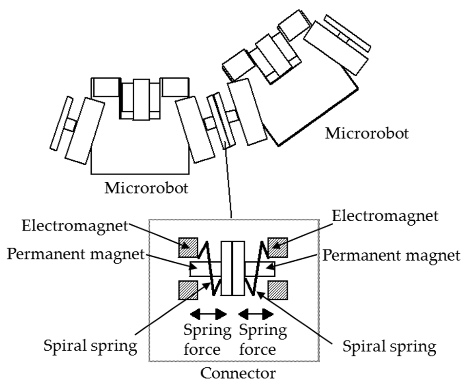
Figure 5.
Interaction between microrobots. The spiral spring connected between the microrobot body and the connector device is extended compared to its natural length. The connector can be automatically attached and detached by electromagnets, and after connection, the connection is held by the magnetic attraction force of the permanent magnets arranged inside the connector.
Figure 6.
Hoop force acting on the microrobot. The spring force is converted to the microrobot coordinate system and used as an external force in the equation of motion. The hoop force is the force component acting in the negative z direction of the microrobot coordinate system.
Figure 6.
Hoop force acting on the microrobot. The spring force is converted to the microrobot coordinate system and used as an external force in the equation of motion. The hoop force is the force component acting in the negative z direction of the microrobot coordinate system.
Figure 7.
Non-driving microrobot pulled up by the driving microrobot. The non-driving microrobot can climb the small cylinder in the multiple connected state by being pulled up by the driving microrobot. While climbing, the load on the non-driving microrobot is only the gravity load acting in the vertically downward direction. The microrobots are connected through a connector device, and a force acts in the perpendicular direction to the expansion and contraction direction of the spiral spring.
Figure 8.
Image of multiple connected movement. First, by focusing on the motion of each individual microrobot, as the simulation time progresses from t0 to t1 to t2, the respective position of each microrobot will change based on the applied rotational speed, acting gravity, and wheel magnetic attraction force.
Figure 9.
The relationship between the magnetic attraction force of the upper and lower wheels of a single microrobot capable of vertical movement up and down. We observed that a larger magnetic attraction force is required for the upper wheels when descending than when climbing. It is better if the magnetic attraction force of the lower wheels is larger and the magnetic attraction force of the upper wheel is smaller when climbing, and the opposite is true for descending.
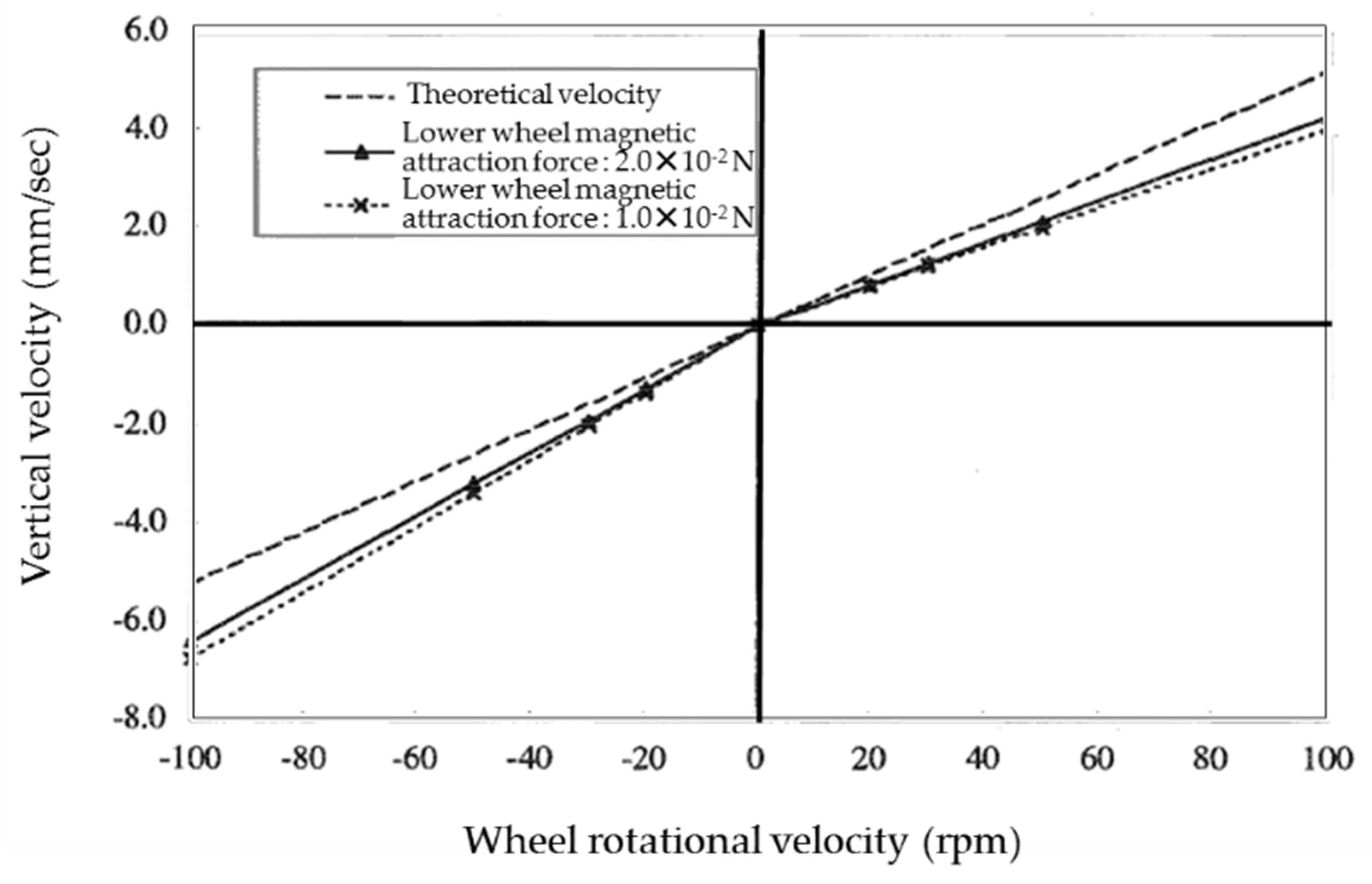
Figure 10.
Relationship between the vertical velocity and wheel rotational velocity. Due to the impact of gravity, the observed vertical velocity was lower than the theoretical velocity when climbing and higher than the theoretical velocity when descending.
Figure 10.
Relationship between the vertical velocity and wheel rotational velocity. Due to the impact of gravity, the observed vertical velocity was lower than the theoretical velocity when climbing and higher than the theoretical velocity when descending.
Figure 11.
Relationship between the slip ratio and the magnetic attraction force of the lower wheels when climbing and descending at 100 rpm. For both climbing and descending, the slip ratio decreases as the gripping force increases with the increase in the magnetic attraction force of the lower wheels. Since the slip ratio was observed to converge to a particular value, the climbing velocity converges not to the theoretical velocity.
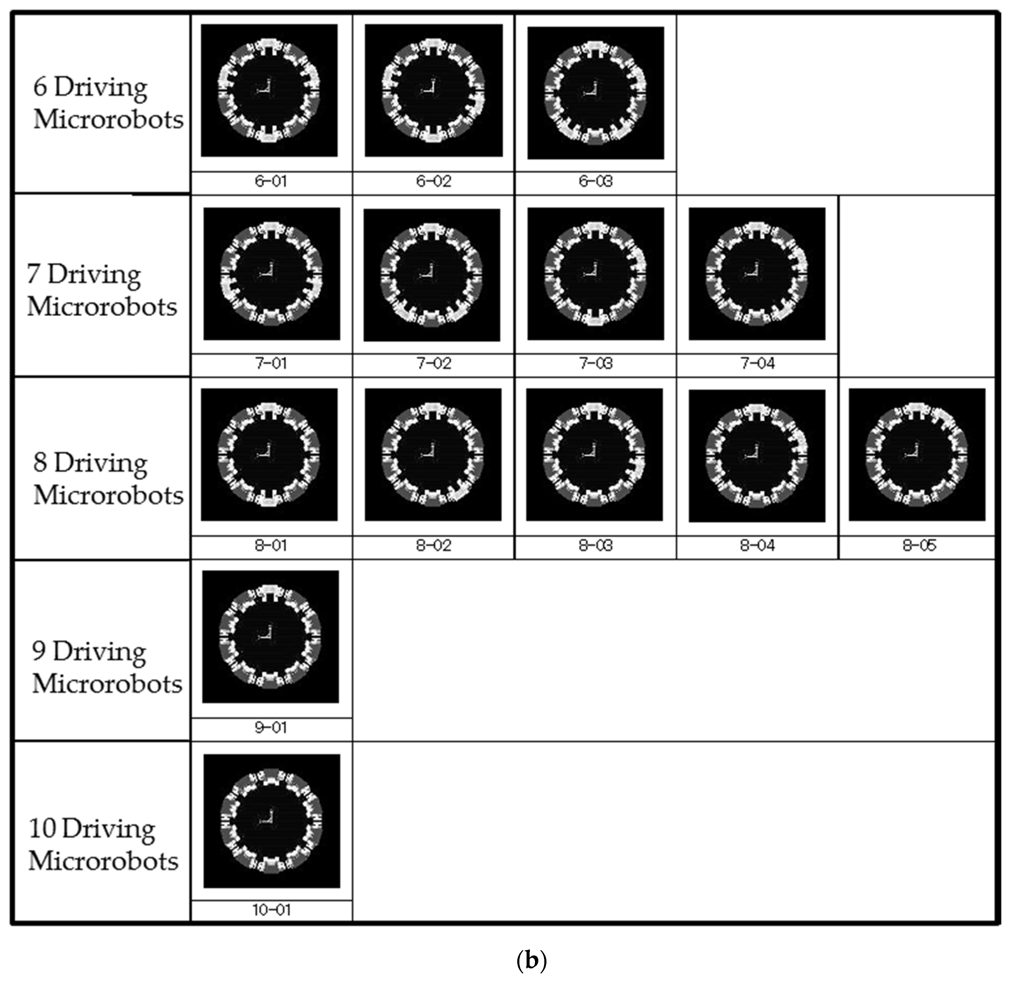
Figure 12.
Layout patterns when surrounding the pipe with 10 microrobots. All combinations of driving microrobots and non-driving microrobots when surrounding the pipe with 10 microrobots are shown. Gray microrobots are the driving microrobots and white microrobots are the non-driving microrobots. (a) Layout patterns for 1 to 5 driving microrobots and (b) layout patterns for 6 to 10 driving microrobots.
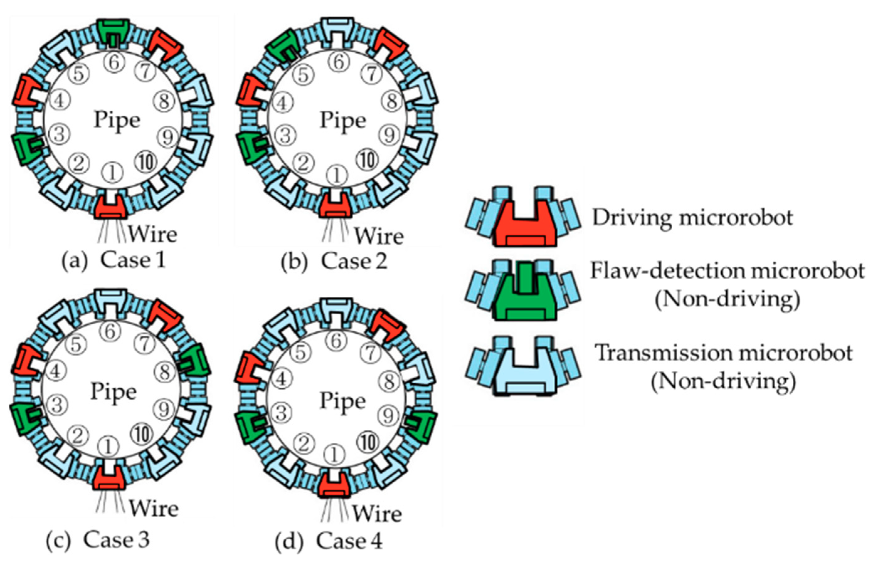
Figure 13.
Ten microrobots were arranged around a pipe. There were three types of microrobots: a driving microrobot that has driving devices, a flaw-detection microrobot that has a flaw-detection sensor but does not have driving devices, and a transmission microrobot that transmits power and sensor signals but does not have driving devices. Four cases are shown, in which the positions of the two flaw-detection microrobots are different. In case 1 and case 2, the flaw-detection microrobots were placed between the driving microrobots ① and ④, and ④ and ⑦. In case 1, the flaw-detection microrobots were placed on the right side of the driving microrobots ④ and ⑦. In case 2, the flaw-detection microrobots were placed on both sides of the driving microrobot ④. In case 3 and case 4, the flaw-detection microrobots were placed between the driving microrobots ① and ④, and ① and ⑦. The difference between cases 3 and 4 was the presence or absence of the driving microrobot next to the flaw-detection microrobot between the driving microrobots ① and ⑦.
![Micromachines 10 00524 g013]()
Figure 14.
Difference between the elevation displacement of each microrobot from the parent microrobot ①. The other microrobots are being pulled up by microrobots ①, ④, and ⑦, which are the driving microrobots. The gaps between microrobots ⑦ and ⑧ and between microrobots ⑩ and ① were the largest, and the maximum was approximately 75 μm.
Figure 15.
Image of non-driving microrobot pulled up by driving microrobot. mg is the gravity force.
Figure 15.
Image of non-driving microrobot pulled up by driving microrobot. mg is the gravity force.
Figure 16.
Simulation results (animation display) of 10 connected microrobots. Red microrobots show driving microrobots and blue microrobots show non-driving microrobots. The animation result shows that three driving microrobots can move seven non-driving microrobots.
Figure 16.
Simulation results (animation display) of 10 connected microrobots. Red microrobots show driving microrobots and blue microrobots show non-driving microrobots. The animation result shows that three driving microrobots can move seven non-driving microrobots.
Figure 17.
Prototype of a microrobot for evaluating the independent vertical driving performance of a microrobot. A cylinder made of magnetic stainless steel (SUS 430) with a diameter of 22 mm and a height of 30 mm was used in the experiment as a target object simulating a pipe.
Figure 17.
Prototype of a microrobot for evaluating the independent vertical driving performance of a microrobot. A cylinder made of magnetic stainless steel (SUS 430) with a diameter of 22 mm and a height of 30 mm was used in the experiment as a target object simulating a pipe.
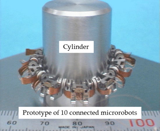
Figure 18.
Prototype of 10 connected microrobots for evaluating the vertical driving performance with 10 connected microrobots. Ten microrobots were arranged around a cylinder simulating a pipe. There were three types of microrobots: a driving microrobot with driving devices, a flaw-detection microrobot with a flaw-detection sensor but no driving device, and a transmission microrobot with transmit power and sensor signals but no driving device.
Figure 19.
Configuration of a prototype of a magnetic wheeled microrobot with four types of functional devices: driving devices, reduction gear and wheel devices, micro connectors, and a flaw-detection device.
Figure 19.
Configuration of a prototype of a magnetic wheeled microrobot with four types of functional devices: driving devices, reduction gear and wheel devices, micro connectors, and a flaw-detection device.
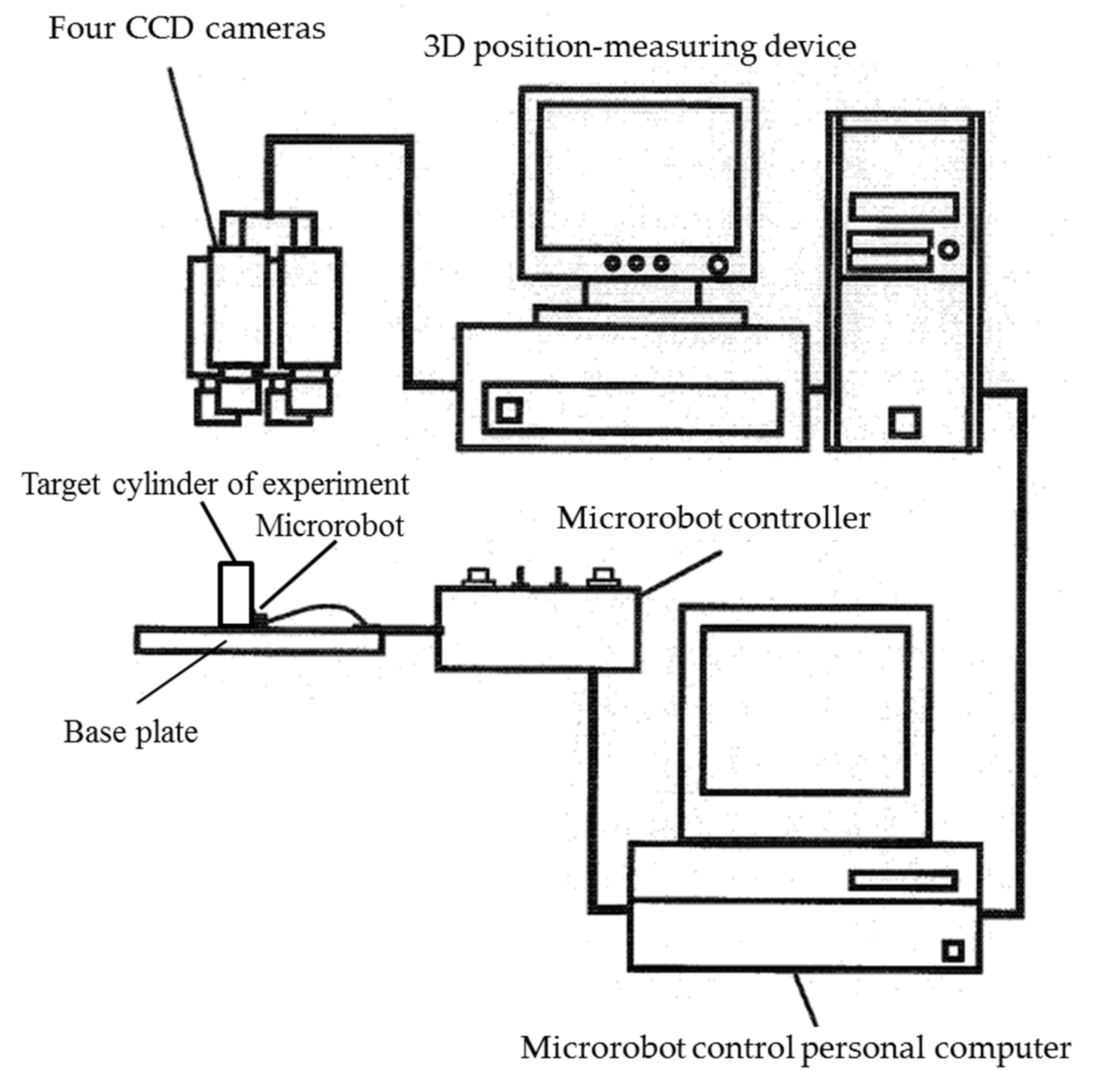
Figure 20.
Microrobot vertical driving performance evaluation and control system. The system consisted of six parts: (1) 4 CCD cameras to capture images of the microrobots, (2) a 3D position-measuring device to extract the three color marks from the images and measure the position and orientation of the microrobots, (3) a computer that outputs a control signal to control the microrobot by executing the control program based on the position information, (4) a microrobot controller to drive the driving device of the microrobot after receiving the control signal, (5) the microrobot that is controlled, and (6) the target cylinder simulating a pipe on a base plate.
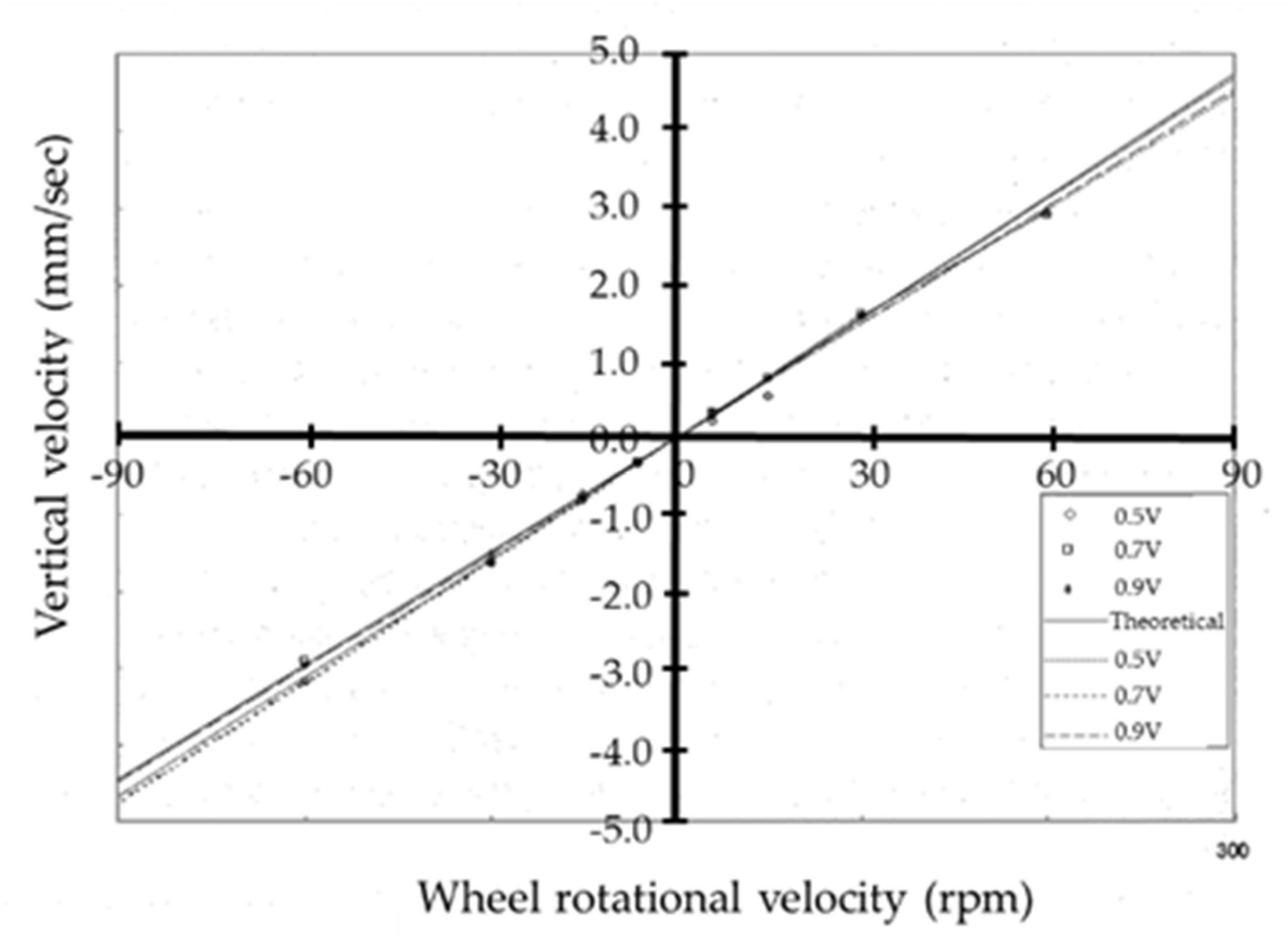
Figure 21.
The relationship between the wheel rotational velocity and climbing velocity in the vertical direction obtained from the measurement results. Descending movement is indicated by negative wheel rotational velocity values, the straight line is the theoretical value of the wheel rotational velocity, and the dashed lines are the result of approximating the measurement results, using the least squares method, to straight lines passing through the origin.
Figure 22.
The layout of 10 connected microrobots and the arrangement of the marks for measurement. Among the 10 connected microrobots, the driving microrobot consisted of 3 microrobots: 1 main microrobot receiving the power supply by wire and 2 sub-microrobots receiving the power supply from the main microrobot through the connector; both are shown enclosed in a box. Three marks were illustrated in the main microrobot and the opposite microrobot. One mark each was illustrated for the other eight microrobots, and a different colored mark was used for the adjacent microrobot.
Figure 23.
Path of the marks on the microrobots during vertical (a) climbing and (b) descending by the connected microrobots. The path spread at the points indicated by the thick arrows in (b) because the microrobots were being driven even after reaching the base plate, and the wheels slipped on the base plate, causing the microrobots to vibrate.
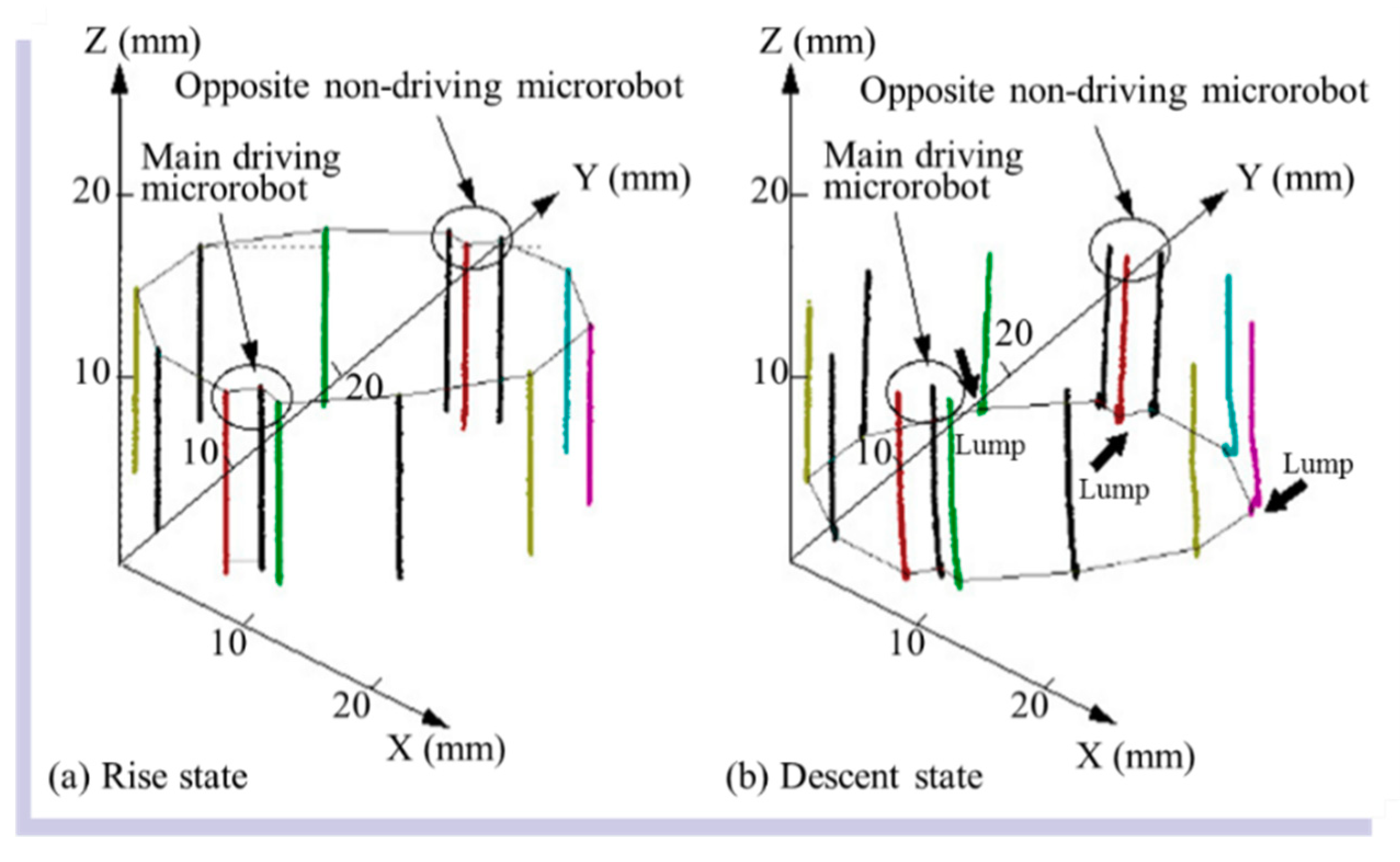
Figure 24.
Measurement results of the position of the 10 microrobots when (a) rising and (b) descending. The X-axis represents the tangential direction, the Y-axis represents the radial direction, and the Z-axis represents the axial direction of the cylinder. There was almost no change in the in-plane position (X and Y directions) on the base plate, for both climbing and descending. From (b), the position of the Z-direction does not change after approximately six seconds when descending.
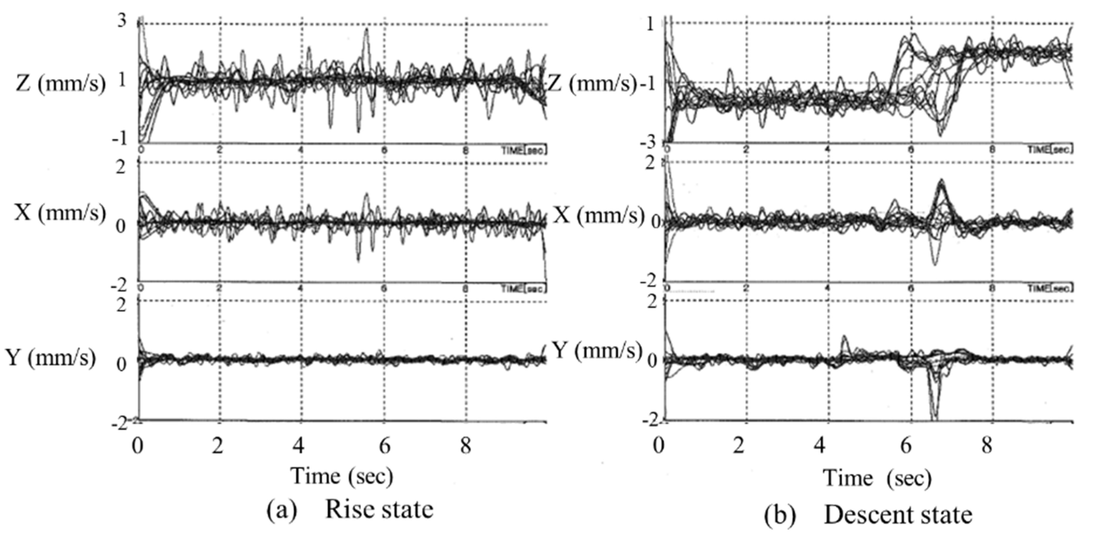
Figure 25.
Measurement results of the velocity of 10 microrobots in the (a) climbing and (b) descending states. The velocity in the Z-direction when descending is twice that when climbing. The velocity change in the Y-direction is small compared to the other two directions as the movement of the microrobots is restricted by the cylinder wall. The velocity fluctuation in the three directions is high in the time range between 0 and 1 s.
Table 1.
Simulation results of 10 connected microrobots’ movements surrounding a pipe. Layout No. indicates the same numbers shown in
Figure 12. In the yellow background case, the robot is disconnected, and the pipe cannot be climbed.
Table 1.
Simulation results of 10 connected microrobots’ movements surrounding a pipe. Layout No. indicates the same numbers shown in
Figure 12. In the yellow background case, the robot is disconnected, and the pipe cannot be climbed.
| Layout No. | Rise Height Average Value (mm) | Rise Height Standard Deviation (mm) | Lateral Standard Deviation (mm) | Rotational Standard Deviation (deg) | Remarks |
|---|
| 1-01 | 0.41 | 0.6 | 0.05 | 2.22 | Disconnected |
| 2-01 | 1.21 | 0.6 | 0.08 | 3.34 | Disconnected |
| 2-02 | 1.03 | 0.68 | 0.06 | 2.72 | Disconnected |
| 2-03 | 1.15 | 0.91 | 0.08 | 2.9 | Disconnected |
| 2-04 | 1.09 | 1.05 | 0.09 | 3.21 | Disconnected |
| 2-05 | 0.82 | 0.96 | 0.09 | 3.17 | Disconnected |
| 3-01 | 9.13 | 0.42 | 0.07 | 2.67 | |
| 3-02 | 8.94 | 0.5 | 0.06 | 3.16 | |
| 3-03 | 8.02 | 1.22 | 0.23 | 4.89 | |
| 3-04 | 2.61 | 1.76 | 0.24 | 6.29 | Disconnected |
| 4-01 | 9.54 | 0.25 | 0.04 | 1.58 | |
| 4-02 | 9.52 | 0.23 | 0.02 | 1.63 | |
| 4-03 | 9.34 | 0.59 | 0.11 | 2.64 | |
| 5-01 | 10.02 | 0.09 | 0 | 0 | |
| 5-02 | 9.94 | 0.21 | 0.04 | 1.1 | |
| 5-03 | 9.95 | 0.21 | 0.04 | 1.04 | |
| 5-04 | 9.71 | 0.52 | 0.14 | 2.36 | |
| 5-05 | 9.86 | 0.26 | 0.05 | 1.44 | |
| 5-06 | 9.86 | 0.25 | 0.04 | 1.56 | |
| 5-07 | 9.72 | 0.53 | 0.13 | 2.37 | |
| 5-08 | 9.23 | 1.04 | 0.28 | 4.07 | |
| 5-09 | 9.63 | 0.5 | 0.1 | 2.53 | |
| 5-10 | 9.24 | 1.05 | 0.28 | 4 | |
| 5-11 | 9.65 | 0.51 | 0.12 | 2.37 | |
| 5-12 | 1.74 | 1.11 | 0.11 | 3.52 | Disconnected |
| 6-01 | 10.06 | 0.09 | 0.01 | 0.5 | |
| 6-02 | 10.06 | 0.09 | 0.01 | 0.5 | |
| 6-03 | 10.06 | 0.09 | 0.01 | 0.5 | |
| 7-01 | 10.11 | 0.09 | 0.01 | 0.63 | |
| 7-02 | 10.11 | 0.1 | 0.01 | 0.54 | |
| 7-03 | 10.11 | 0.1 | 0.02 | 0.53 | |
| 7-04 | 10.11 | 0.11 | 0.02 | 0.4 | |
| 8-01 | 10.15 | 0.09 | 0.01 | 0.55 | |
| 8-02 | 10.15 | 0.09 | 0.02 | 0.53 | |
| 8-03 | 10.15 | 0.1 | 0.02 | 0.4 | |
| 8-04 | 10.15 | 0.1 | 0.02 | 0.4 | |
| 8-05 | 10.06 | 0.27 | 0.06 | 1.24 | |
| 9-01 | 10.19 | 0.08 | 0.01 | 0.39 | |
| 10-01 | 10.23 | 0 | 0 | 0 | |
Table 2.
Difference between the elevation displacement of each microrobot from the parent microrobot ①.
Table 2.
Difference between the elevation displacement of each microrobot from the parent microrobot ①.
| | ① | ② | ③ | ④ | ⑤ | ⑥ | ⑦ | ⑧ | ⑨ | ⑩ |
| Case 1 | 0.0 | −48.9 | −28.0 | 24.7 | −37.0 | −37.5 | 0.9 | −72.8 | −97.8 | −74.1 |
| Case 2 | 0.0 | −37.5 | −43.3 | 19.7 | −42.4 | −37.1 | 0.4 | −72.7 | −97.7 | −73.2 |
| Case 3 | 0.0 | −45.1 | −29.3 | 27.0 | −33.7 | −35.7 | 0.2 | −74.9 | −99.2 | −74.0 |
| Case 4 | 0.0 | −44.8 | −28.8 | 27.7 | −32.9 | −34.3 | 1.7 | −73.5 | −99.3 | −74.3 |


