Article

Improved MRD 4H-SiC MESFET with High Power Added Efficiency

School of Microelectronics, Xidian University, Xi’an 710071, China
*
Author to whom correspondence should be addressed.
Micromachines 2019, 10(7), 479; https://doi.org/10.3390/mi10070479
Submission received: 5 June 2019 / Revised: 8 July 2019 / Accepted: 12 July 2019 / Published: 17 July 2019
(This article belongs to the Special Issue Miniaturized Transistors, Volume II)

Abstract

:
An improved multi-recessed double-recessed p-buffer layer 4H–SiC metal semiconductor field effect transistor (IMRD 4H-SiC MESFET) with high power added efficiency is proposed and studied by co-simulation of advanced design system (ADS) and technology computer aided design (TCAD) Sentaurus software in this paper. Based on multi-recessed double-recessed p-buffer layer 4H–SiC metal semiconductor field effect transistor (MRD 4H-SiC MESFET), the recessed area of MRD MESFET on both sides of the gate is optimized, the direct current (DC), radio frequency (RF) parameters and efficiency of the device is balanced, and the IMRD MESFET with a best power-added efficiency (PAE) is finally obtained. The results show that the PAE of the IMRD MESFET is 68.33%, which is 28.66% higher than the MRD MESFET, and DC and RF performance have not dropped significantly. Compared with the MRD MESFET, the IMRD MESFET has a broader prospect in the field of microwave radio frequency.

1. Introduction

Nowadays, as the device size continues to decrease, the process difficulty increases significantly, both the power consumption and non-ideal effects are significant. The first-generation semiconductor Si and other materials are close to their theoretical limits in performance, while 4H Silicon Carbide (4H-SiC) has a wide band gap (3.26 eV), high thermal conductivity (4.9 W/(cm·K)), high breakdown electric field (4 MV/cm) and low dielectric constant (9.7), high electron saturation drift speed (2.7 × 107 cm/s), and exhibits superior performance compared to 3C-SiC, 6H-SiC, Si, GaAs, and so on. Based on the excellent characteristics of 4H-SiC, 4H-SiC metal semiconductor field transistors (4H-SiC MESFETs) are expected to be applied to various semiconductor fields [1,2,3]. However, current research on 4H-SiC MESFET mainly includes breakdown voltage, saturation drain current, electron saturation drift speed, frequency characteristics etc. [4,5,6,7,8,9,10]. There are a variety of ways to improve device performance, such as the use of double-recessed gates [4], recessed buffers and diffusion regions [5,6], doping distribution modification [7,8], silicon-on-insulator (SOI) technology [9,10] and so on, which can significantly improve device performance. At the same time, there is little research on efficiency [11,12]. For non-conventional 4H-SiC-based FETs, the characteristics of the device can be studied using numerical simulations [13,14,15,16,17].
In this paper, we reported a 4H-SiC MESFET with improved multi-recessed double-recessed p-buffer layer (IMRD) structure. Traditional 4H-SiC MESFETs have been experimentally verified. Many experimental results have been reported so far [18,19], but they are all fixed structures, and the effect of structural parameters on the results has not been studied. Based on multi-recessed 4H–SiC MESFETs with double-recessed p-buffer layer (MRD 4H-SiC MESFET) [20], we adopt a new design method optimized by technology computer aided design (TCAD) simulation and verified in advanced design system (ADS) software. The IMRD MESFET has both the excellent performance of MRD MESFET and better power-added efficiency (PAE) and provides a new idea for high-power operational amplifier design at the device level.

2. Device Structure and Description

Figure 1a,b are the cross-sectional views of the MRD MESFET and the IMRD MESFET, respectively. In Figure 1a, the MRD MESFET contains a high-purity semi-insulating substrate (SI-Substrate), a p-type buffer layer (P-Buffer), an n-type channel layer (N-Channel), and two doped n-type cap layers (Source and Drain), the Nickel Schottky gate has a work function of 5.1 eV. By high energy ion implantation and high temperature annealing processes, two recessed areas are formed on both sides of the gate. The main difference between the two devices is the recessed regions on both sides of the gate. The length and width on both sides are L1 = 0.15 μm, L2 = 0.2 μm, H1 = 0.1 μm and H2 = 0.1 μm, other parameters are shown in Table 1. In the optimized IMRD MESFET, L1 = 0.5 μm, L2 = 0.2 μm, H1 = 0.15 μm and H2 = 0.2 μm, and the other parameters are consistent with the MRD MESFET.
The 2D TCAD simulator, Sentaurus is used in this paper. The simulation temperature is set to 300 K. A 5.1 eV Nickel Schottky gate work function is applied. The main model used in the simulation are Mobility (Enormal Doping Dep HighFieldsaturation (GradQuasiFermi)), Recombination (Auger SRH (DopingDep)), Incomplete Ionization, Effective Intrinsic and Density (BandGapNarrowing (OldSlotboom)) [21]. The interface state has a great impact on the device, in this paper, the gate of the two devices are formed by a metal-to-SiC contact to form a Schottky contact, so the gate does not have to consider the interface state. When the MESFET is passivated with a material such as Si3N4 or SiO2, the performance is slightly degraded. When verifying the conventional 4H-SiC MESFET, Si3N4 was used as the passivation layer. When Si3N4 is used as the passivation layer, the device performance is reduced by less than SiO2 [22,23]. As a theoretical analysis, the influence of passivation on the device is not considered here. After obtaining the simulation results, the obtained model parameters are used in the ADS software to measure the PAE of the two devices. In the ADS simulation, the bias conditions of the device are shown in Figure 2. Direct current (DC) voltage Vg1 is −3.5 V, Vdd is 28 V, input power Pavs is 24 dBm, and frequency f is 1.2 GHz.

3. Results and Discussion

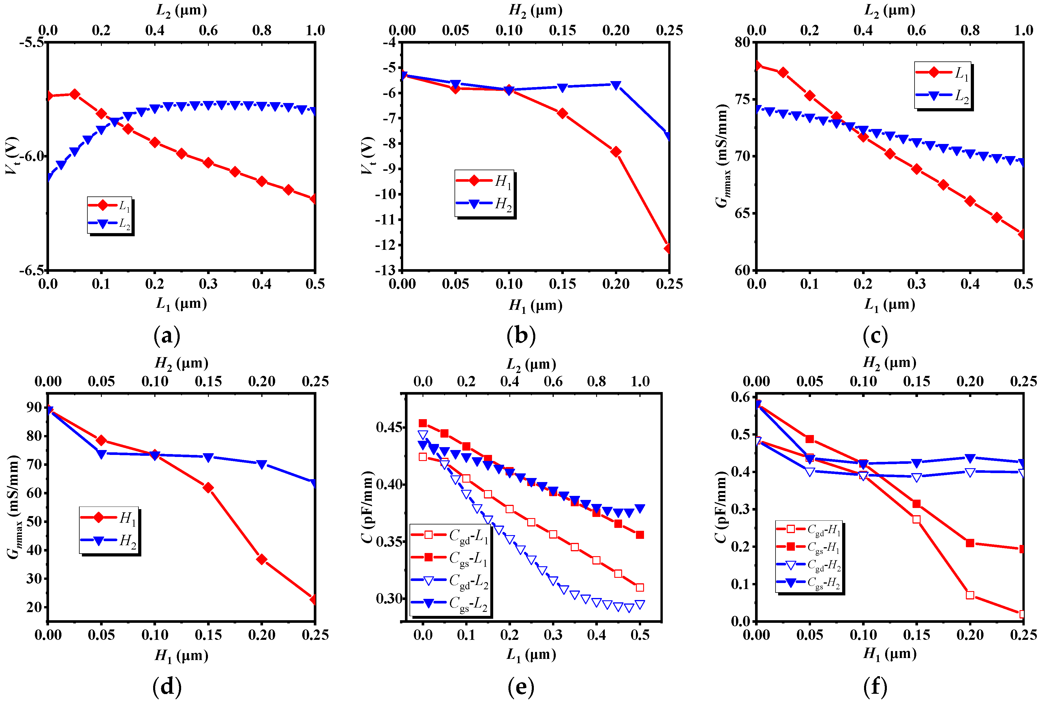
3.1. Effect of the Length and Height of the Recessed Regions on the PAE

The effect of the length and height of the recessed regions on PAE is shown in Figure 3. When a parameter changes, the remaining parameters are the default values in Figure 1a. We can see in Figure 3a, when L1 increases, PAE also increases. When L1 reaches 0.5 μm, PAE reaches a maximum value; when L2 is less than 0.1 μm, the PAE increases with L2. When L2 reaches 0.2 um, PAE reaches a maximum value. When L2 is larger than 0.1 μm, PAE decreases with the increase of L2. In Figure 3b, the trend of the effect of H1 and H2 on PAE agrees well. When H1 and H2 are less than 0.2 μm, PAE of H1 and H2 increase with the increase of H1 and H2. When H1 and H2 reach 0.2 μm, PAE of H1 and H2 reach the maximum value. When H1 and H2 are larger than 0.2 μm, PAE of H1 and H2 decrease as H1 and H2 increases.

3.2. Optimized Results and Mechanism Discussion

Through further analysis of the results obtained in 3.1, we found that between L1, L2, H1 and H2 there is a relatively independent relationship. When L2, H1 and H2 take different values, the trend of PAE with L1 is almost the same as Figure 3a. The maximum value of PAE is found in L1 = 0.5 μm. In addition, for L2, H1 and H2, the maximum value of PAE are found in L2 = 0.2 μm, H1 = 0.2 μm and H2 = 0.2 μm. Based on the above results, L1 = 0.5 μm, L2 = 0.2 μm, H1 = 0.2 μm and H2 = 0.2 μm were selected as the optimal structural parameters, and the optimized device was obtained. The main parameters of the device are shown in Table 2. It can be seen from the table that although its saturated drain current Idsat is too small, which is 35.2% lower than that of the MRD MESFET, and the DC characteristics are greatly weakened, its PAE reaches 70.85%, which is 33.40% higher than that of the MRD MESFET.
Figure 4 shows the effect of the length and height on Idsat. It can be seen from Figure 4a that when L1 = 0.5 μm and L2 = 0.2 μm, the decline of Idsat is small; In Figure 4b, it can be clearly seen that when H1 is less than 0.15 μm, Idsat decreases, but the value of decrease is not very large. When H1 is greater than 0.15 μm, Idsat drops sharply. Similarly, for H2, when H2 is less than 0.2 μm, the decrease of Idsat is not large. When H2 is larger than 0.2 μm, the decline of Idsat is more obvious. The main cause of the weakening of the DC characteristics is that the thickness of the channel region becomes extremely thin, resulting in narrowing the channel of most electrons, and thus the DC characteristics are deteriorated. Based on the results above, L1 = 0.5 μm, L2 = 0.2 μm, H1 = 0.15 μm and H2 = 0.2 μm were selected as structural parameters, and the PAE was measured to be 68.33%. After optimization, the PAE of the IMRD MESFET is 28.66% higher than that of the MRD MESFET.
Figure 5 illustrates the effect of recessed region parameters (L & H) on Vt, Gmmax, Cgs and Cgd, the transconductance Gmmax, its physical meaning is the first-order partial conductance of the output drain current and the input voltage, Cgs is the gate-source capacitance, and Cgd is the gate-drain capacitance. In combination with Figure 3, it can be seen from Figure 5a,c,e that as L1 increases, the threshold voltage Vt, the transconductance Gmmax, the gate-source capacitance Cgs and the gate-drain capacitance Cgd decrease, but the PAE gradually increases; when L2 increases, Vt increases first, then tends to be stationary, Gmmax gradually decreases, the change trend of Cgd and Cgs are about the same. When L2 is less than 0.1 μm, the changes of Cgs and Cgd are relatively stable. When L2 is larger than 0.1 μm, Cgs and Cgd are gradually increased. Combined with Figure 3a and Figure 5a,c,e, it can be found that the effects of Cgs and Cgd on PAE are obvious. It can be seen from the bias conditions of Figure 2 that Cgs and Cgd affect the input impedance and output impedance respectively, and the power consumed by the capacitor is proportional to the size of the capacitor. According to the definition of PAE, these two capacitors affect the input power and output power, so these two capacitors have a greater impact on the PAE. Similarly, in conjunction with Figure 3, it can be seen from Figure 5b,d,f that, when H1 is less than 0.2 μm, as H1 increases, Vt, Gmmax, Cgs and Cgd decrease, while PAE increases. When H1 is larger than 0.2 μm, PAE decreases with H1. For H2, when H2 increases gradually, Vt and Gmmax also decrease gradually, but when H2 is less than 0.05 μm, Cgs and Cgd decrease with increasing H2. When H2 is greater than 0.05 μm, the change of Cgs and Cgd are relatively stable. When H2 is less than 0.2 μm, PAE increases with the increase of H2. When H2 is greater than 0.2 μm, PAE decreases as H2 increases. Combined with Figure 3b, Figure 4b and Figure 5b,d,f, although the capacitances Cgs and Cgd have a greater influence on PAE, as the H2 increases, the conductive channel of the device still decreases. When the thickness of the conductive channel is less than 0.05 μm, the conductive channel is extremely thin, and its conductive properties are greatly weakened. At this time, both the AC signal and the DC signal will be greatly attenuated in the channel, resulting in a decrease in output power. Under the combined action of several factors, the PAE decreases as H2 increases.
The power-added efficiency (PAE) is the difference in output and input power in place of radio frequency (RF) output power in the drain efficiency equation, which takes power gain Gp into account.
PAE = P out P in P dc = η c ( 1 1 G p )
ηc is the drain efficiency and represents the ratio of output power to DC input power. In order to obtain a higher PAE, a larger power gain Gp is required. It can be seen from the equivalent circuit diagram of the device, the size of the PAE is determined by these parameters together. For the threshold voltage Vt, only when the absolute value of Vt is reduced, can small voltage make the channel turn on. When the input voltage is constant, the smaller the absolute value of the threshold voltage is, the larger the channel current is, and the larger the output power Pout is, so that the PAE becomes larger. When Gmmax is reduced, its DC characteristic will also decrease. Since the input voltage is constant, the decrease of Gmmax causes the bias current Id to decrease, so that the Pdc is reduced, according to the definition of PAE, the decrease of Pdc will cause the increase of PAE. The gate-source capacitance Cgs and the gate-drain capacitance Cgd have a greater influence on the PAE, in the equivalent circuit, Cgs and Cgd are in the input loop and output loop respectively. Because of the larger Cgs in the bias, the more AC input energy it consumes, the larger the Cgd, the smaller the AC output power of the load is. In addition, as the channel becomes thinner and thinner, it affects both the capacitance and the carrier’s passage through the channel region. Although the PAE increases as the capacitance decreases, the extremely thin channel also makes the DC and AC characteristics affected seriously. From the analysis of 3.1–3.3, when the structural parameters of the device are changed, in order to obtain the optimal PAE, it is necessary to weigh the various parameters and find the optimal structural parameters on the premise that the other performance is guaranteed. Perhaps the above design process will sacrifice a small part of the performance, but the efficiency is greatly improved, achieving energy saving and emission reduction, which is very beneficial to the construction of green earth.

4. Conclusions

An improved MRD 4H-SiC MESFET with high power added efficiency is analyzed and studied by co-simulation of ADS and TCAD Sentaurus software in this paper. Based on MRD 4H-SiC MESFET, we optimize the MRD MESFET on both sides of the gate. In the recessed area, the DC, RF parameters and efficiency of the device are weighed, and the IMRD MESFET with the best PAE is finally obtained. The results show that the saturation drain current Idsat of the IMRD MESFET is 311 mA, the threshold voltage Vt is −6.99 V, the maximum transconductance Gmmax is 46.37 mS, the gate-source capacitance Cgs is 0.218 pF, and the gate-drain capacitance Cgd is 17.9 fF. The PAE is 68.33%, which is 28.66% higher than the MRD MESFET, and DC and RF performance have not dropped significantly. This paper proposes to lay a device-level theoretical basis and design method for further energy-efficient RF power amplifier.

Author Contributions

Project administration, H.J.; writing—original draft preparation, S.Z.; writing—review and editing, X.W., T.L., Y.Y.; Data curation, Y.T.; Formal analysis, Y.L.

Funding

This work was supported by the National Natural Science Foundation of China (NSFC) under Grant No. 61671343.

Conflicts of Interest

The authors declare no conflict of interest.

References

  1. Murugapandiyan, P.; Ravimaran, S.; William, J. DC and microwave characteristics of Lg 50 nm T-gate InAlN/AlN/GaN HEMT for future high power RF applications. AEU Int. J. Electron. Commun. 2017, 31, 163–168. [Google Scholar] [CrossRef]
  2. Prasad, D.A.; Komaragiri, R. Performance comparison of 4H-SiC MESFETs. In Proceedings of the 2013 Annual International Conference Emerging Research Areas and 2013 International Conference on Microelectronics, Communications and Renewable Energy (AICERA/ICMiCR), Kanjirapally, India, 4–6 June 2013; pp. 1–5. [Google Scholar]
  3. Kesilmis, Z.; Avc, M.; Aksoy, M. An Operational Transconductance Amplifier with 45 nm FINFET Technology; CiteSeerX Scientific Literature Digital Library, Penn State University’s School of Information Sciences and Technology: University Park, PA, USA, 2011. [Google Scholar]
  4. Zhu, C.L.; Tin, C.C.; Zhang, G.H.; Yoon, S.F.; Ahn, J. Improved performance of SiC MESFETs using double-recessed structure. Microelectron. Eng. 2006, 83, 92–95. [Google Scholar] [CrossRef]
  5. Jia, H.; Ma, P.; Luo, Y.; Yang, Z.; Wang, Z.; Wu, Q.; Hu, M. A novel 4H-SiC MESFET with double upper gate and recessed p-buffer. Superlattices Microstruct. 2016, 97, 346–352. [Google Scholar] [CrossRef]
  6. Orouji, A.A.; Shahnazarisani, H.; Anvarifard, M.K. Simulation analysis of a novel dualtrench structure for a high power silicon-on-insulator metal–semiconductor field effect transistor. Mater. Sci. Semicond. Process. 2014, 31, 506–511. [Google Scholar] [CrossRef]
  7. Aminbeidokhti, A.; Orouji, A.A. A novel 4H-SiC MESFET with modified channel depletion region for high power and high frequency applications. Phys. E Low Dimens. Syst. Nanostruct. 2011, 44, 708–713. [Google Scholar] [CrossRef]
  8. Moghadam, H.A.; Orouji, A.A.; Mahabadi, S.E.J. Employing reduced surface field technique by a P-type region in 4H-SiC metal semiconductor field effect transistors for increasing breakdown voltage. Int. J. Numer. Model. Electron. Netw. Devices Fields 2013, 26, 103–111. [Google Scholar] [CrossRef]
  9. Naderi, A.; Heirani, F. A novel SOI-MESFET with symmetrical oxide boxes at both sides of gate and extended drift region into the buried oxide. AEU Int. J. Electron. Commun. 2018, 85, 91–98. [Google Scholar] [CrossRef]
  10. Mohammadi, H.; Naderi, A. A Novel SOI-MESFET with Parallel Oxide-Metal Layers for High Voltage and Radio Frequency Applications. AEU Int. J. Electron. Commun. 2017, 83, 541–548. [Google Scholar] [CrossRef]
  11. Jia, H.; Hu, M.; Zhu, S. An Improved UU-MESFET with High Power Added Efficiency. Micromachines 2018, 9, 573. [Google Scholar] [CrossRef] [PubMed]
  12. Jia, H.; Zhu, S.; Hu, M.; Tong, Y.; Li, T.; Yang, Y. An improved DRBL AlGaN/GaN HEMT with high power added efficiency. Mater. Sci. Semicond. Process. 2019, 89, 212–215. [Google Scholar] [CrossRef]
  13. Singh, J.; Kumar, M.J. A Planar Junctionless FET Using SiC With Reduced Impact of Interface Traps: Proposal and Analysis. IEEE Trans. Electron Devices 2017, 64, 4430–4434. [Google Scholar] [CrossRef]
  14. Della Corte, F.G.; Pezzimenti, F.; Bellone, S.; Nipoti, R. Numerical simulations of a 4H-SiC BMFET power transistor with normally-off characteristics. Mater. Sci. Forum 2011, 679, 621–624. [Google Scholar] [CrossRef]
  15. Lien, W.C.; Damrongplasit, N.; Paredes, J.H.; Senesky, D.G.; Liu, T.J.K.; Pisano, A.P. 4H-SiC N-Channel JFET for Operation in High-Temperature Environments. IEEE J. Electron Devices Soc. 2014, 2, 164–167. [Google Scholar] [CrossRef]
  16. Pezzimenti, F. Modeling of the steady state and switching characteristics of a normally-off 4H-SiC trench bipolar-mode FET. IEEE Trans. Electron Devices 2013, 60, 1404–1411. [Google Scholar] [CrossRef]
  17. Jaikumar, M.G.; Karmalkar, S. Calibration of Mobility and Interface Trap Parameters for High Temperature TCAD Simulation of 4H-SiC VDMOSFETs. Mater. Sci. Forum 2012, 717, 1101–1104. [Google Scholar] [CrossRef]
  18. Chen, Z.; Deng, X.; Luo, X.; Zhang, B.; Li, Z. Improved Characteristics of 4H-SiC MESFET with Multi-recessed Drift Region. In Proceeding of the 2007 International Workshop on Electron Devices & Semiconductor Technology, Beijing, China, 3–4 June 2007. [Google Scholar]
  19. Elahipanah, H. Record gain at 3.1 ghz of 4h-sic high power rf mesfet. Microelectron. J. 2011, 42, 299–304. [Google Scholar] [CrossRef]
  20. Jia, H.; Pei, X.; Sun, Z.; Zhang, H. Improved performance of 4H-silicon carbide metal semiconductor field effect transistors with multi-recessed source/drain drift regions. Mater. Sci. Semicond. Process. 2015, 31, 240–244. [Google Scholar] [CrossRef]
  21. Sentaurus Device User Guide, version L-2016.03; Synopsys Inc.: Mountain View, CA, USA, 2016.
  22. Tenedorio, J.G.; Terzian, P.A. Effects of Si3N4, SiO, and polyimide surface passivations on gaas mesfet amplifier RF stability. IEEE Electron Device Lett. 1984, 5, 199–202. [Google Scholar] [CrossRef]
  23. Charache, G.W.; Akram, S.; Maby, E.W.; Bhat, I.B. Surface passivation of gaas mesfets. IEEE Trans. Electron Devices 1997, 44, 1837–1842. [Google Scholar] [CrossRef]
Figure 1. Schematic cross sections of the (a) MRD 4H-SiC metal semiconductor field effect transistor (MESFET), (b) improved multi-recessed double-recessed p-buffer layer (IMRD) 4H-SiC MESFET.
Micromachines 10 00479 g001
Figure 2. One Tone Load Pull Schematic for power-added efficiency (PAE) measurements.
Micromachines 10 00479 g002
Figure 3. The effect of the (a) length and (b) height on PAE.
Micromachines 10 00479 g003
Figure 4. The effect of the (a) length and (b) height on Idsat.
Micromachines 10 00479 g004
Figure 5. The effect of recessed region parameters on Vt, Gmmax and Cgs. (a) Vt-L. (b) Vt-H. (c) Gmmax-L. (d) Gmmax-H. (e) C-L. (f) C-H.
Micromachines 10 00479 g005
Table 1. Common parameters of the two structures.
ParametersValues
P-Buffer Concentration1.4 × 1015 cm−3
N-Channel Concentration3 × 1017 cm−3
N-Cap layers Concentration2 × 1019 cm−3
Lgs0.5 μm
Lgd1.0 μm
Ls0.5 μm
Ld0.5 μm
Lg0.7 μm
N-Channel Thickness0.25 μm
P-Buffer Thickness0.5 μm
Device Area (without SI-Substrate)1 μm × 3.5 μm
Table 2. Comparison of performance parameters of the two structures.
ParametersMRD MESFETIMRD MESFET
Idsat (mA/mm)358.97233.02
gm (mS/mm)73.4556.37
Vt (V)−5.81−6.89
Cgs (pF/mm)0.1280.13
Cgd (pF/mm)0.390.02
Power-added efficiency (PAE) (%)53.1170.85

