Single Drive Multi-Axis Gyroscope with High Dynamic Range, High Linearity and Wide Bandwidth


Abstract
:
1. Introduction
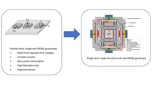
2. Multi-Axis Gyroscope Design and Fabrication
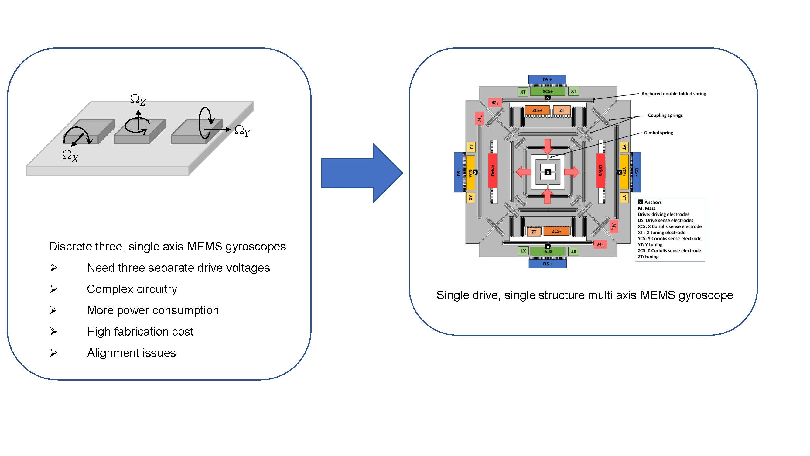
2.1. Mechanical Design
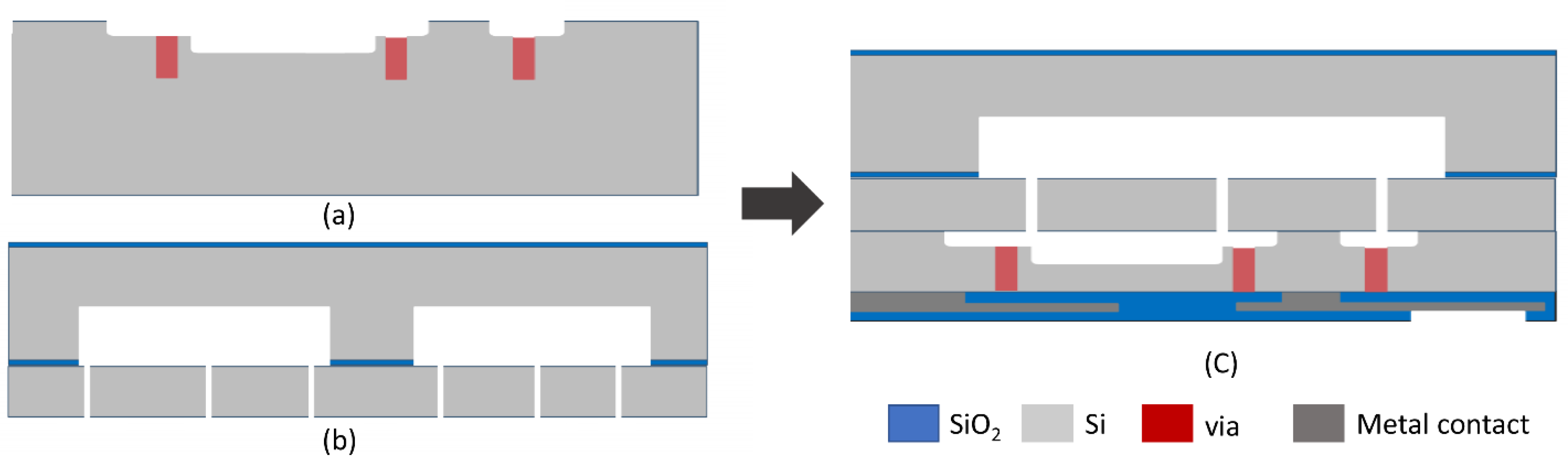
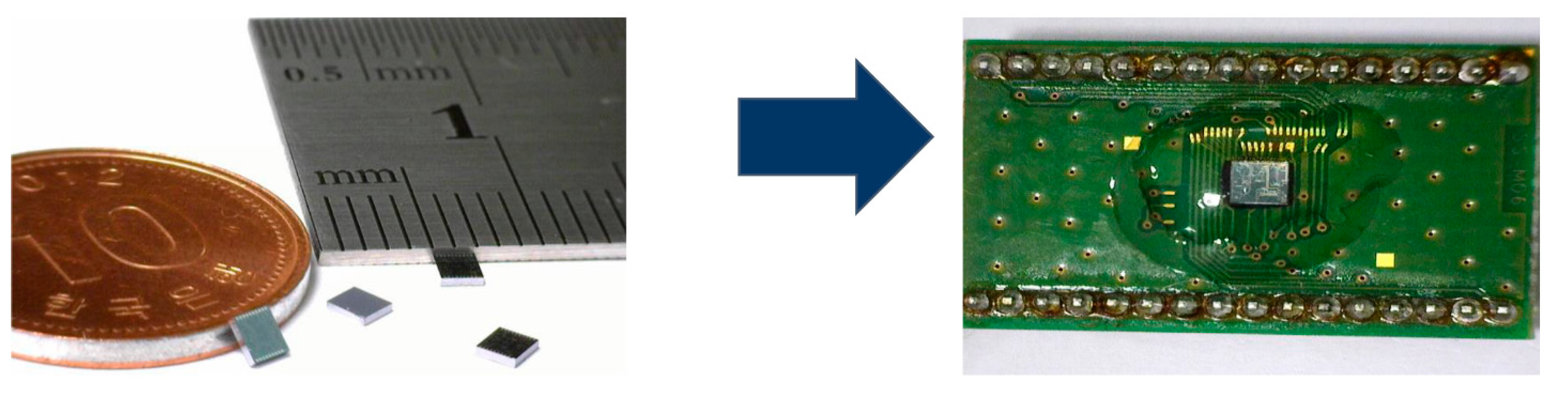
2.2. Fabrication
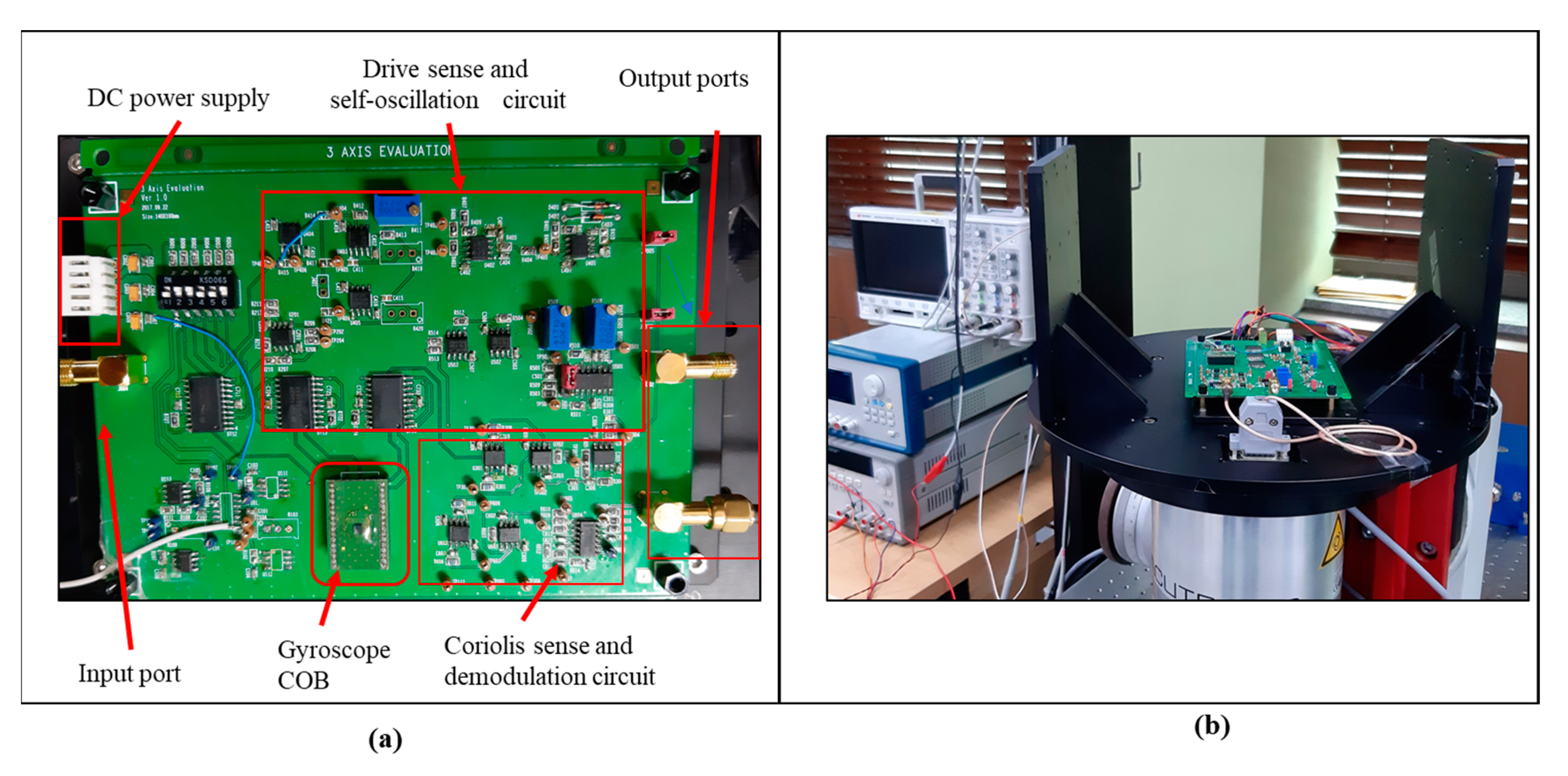
3. Characterization
3.1. Resonant Modes
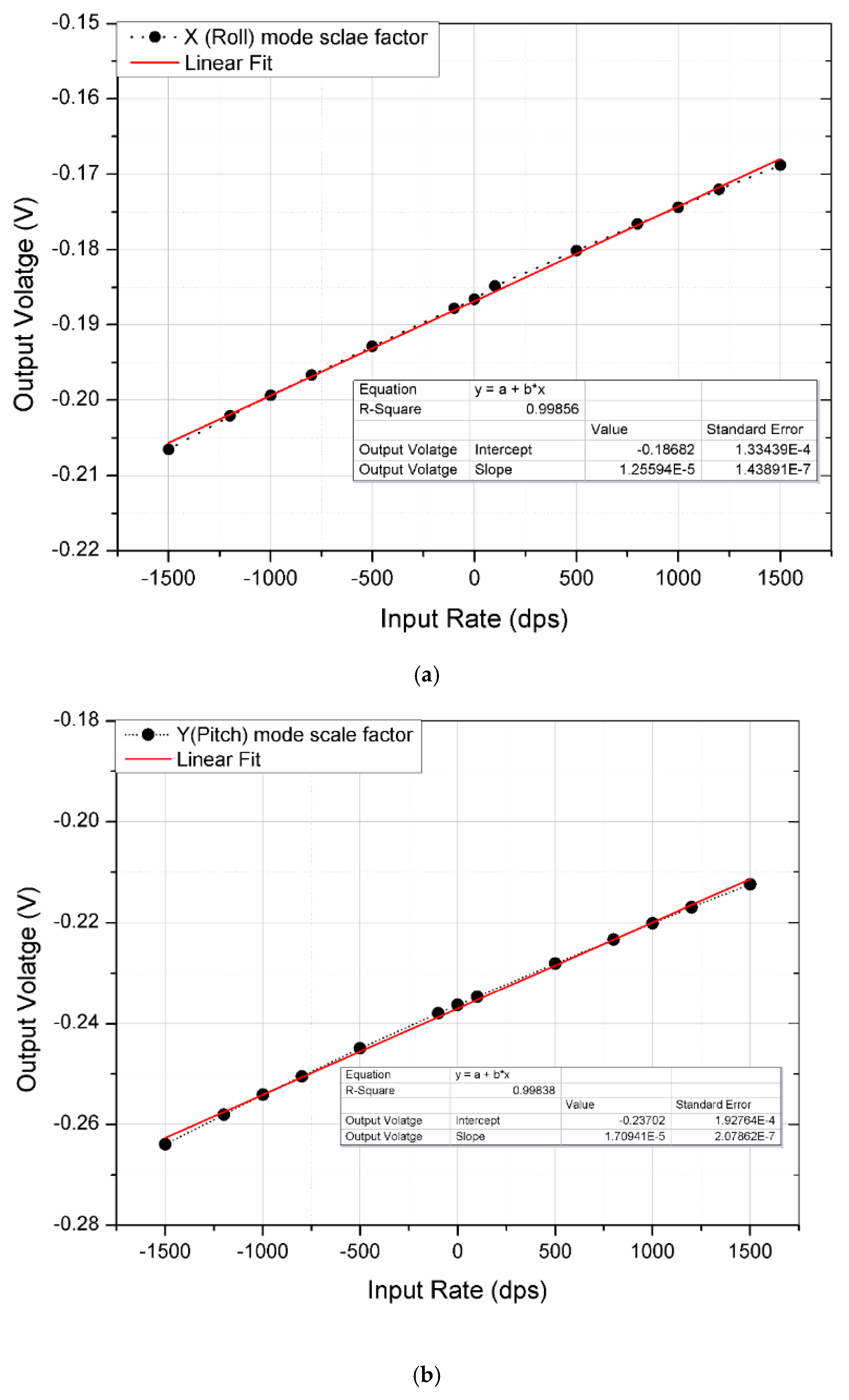
3.2. Angular Rate Response
3.3. Allan Variance
4. Discussion
5. Conclusions and Future Work
Author Contributions
Acknowledgments
Conflicts of Interest
References
- Yazdi, N.; Ayazi, F.; Najafi, K. Micromachined inertial sensors. Proc. IEEE. 1998, 86, 1640–1659. [Google Scholar] [CrossRef]
- Xia, D.; Yu, C.; Kong, L. The development of micromachined gyroscope structure and circuitry technology. Sensors 2014, 14, 1394–1473. [Google Scholar] [CrossRef] [PubMed]
- Acar, C.; Schofield, A.R.; Trusov, A.A.; Costlow, L.E.; Shkel, A.M. Environmentally robust MEMS vibratory gyroscopes for automotive applications. IEEE Sens. J. 2009, 9, 1895–1906. [Google Scholar] [CrossRef]
- Zaman, M.; Sharma, A.; Ayazi, F. High performance matched-mode tuning fork gyroscope. In Proceedings of the 19th IEEE International Conference on Micro Electro Mechanical Systems, Istanbul, Turkey, 22–26 January 2006; pp. 66–69. [Google Scholar]
- Sonmezoglu, S.; Alper, S.E.; Akin, T. An automatically mode-matched MEMS gyroscope with wide and tunable bandwidth. J. Microelectromech. Syst. 2014, 23, 284–297. [Google Scholar] [CrossRef]
- Wu, G.; Chua, G.L.; Gu, Y. A dual-mass fully decoupled MEMS gyroscope with wide bandwidth and high linearity. Sens. Actuators A Phys. 2017, 259, 50–56. [Google Scholar] [CrossRef]
- Perlmutter, M.; Robin, L. High-performance, low cost inertial MEMS: A market in motion! In Proceedings of the 2012 IEEE/ION Position, Location and Navigation Symposium, Myrtle Beach, SC, USA, 23–26 April 2012; pp. 225–229. [Google Scholar]
- Wu, G.; Han, B.; Cheam, D.D.; Wai, L.C.; Chang, P.H.K.; Singh, N.; Gu, Y. Development of Six-Degree-of-Freedom Inertial Sensors With an 8-in Advanced MEMS Fabrication Platform. IEEE Trans. Ind. Electron. 2019, 66, 3835–3842. [Google Scholar] [CrossRef]
- LSM6DSM iNEMO Inertial Module. 2016. Available online: https://www.st.com (accessed on 19 June 2019).
- ST Microelectronics. Everything about STMicroelectronics’ 3-Axis Digital MEMS Gyroscopes. 2011. Available online: https://www.elecrow.com/download/TA0343.pdf (accessed on 19 June 2019).
- Efimovskaya, A.; Yang, Y.; Ng, E.; Chen, Y.; Flader, I.; Kenny, T.W.; Shkel, A.M. Compact roll-pitch-yaw gyroscope implemented in wafer-level epitaxial silicon encapsulation process. In Proceedings of the 2017 IEEE International Symposium on Inertial Sensors and Systems (INERTIAL), Kauai, HI, USA, 27–30 March 2017; pp. 1–2. [Google Scholar]
- Wisher, S.; Shao, P.; Norouzpour-Shirazi, A.; Yang, Y.; Ng, E.; Flader, I.; Chen, Y.; Heinz, D.; Kenny, T.; Ayazi, F. A high-frequency epitaxially encapsulated single-drive quad-mass tri-axial resonant tuning fork gyroscope. In Proceedings of the 2016 IEEE 29th International Conference on Micro Electro Mechanical Systems (MEMS), Shanghai, China, 24–28 January 2016; pp. 930–933. [Google Scholar]
- Yang, B.; Lu, C. Design and analysis of a new three-axis micro-gyroscope. Microsyst. Technol. 2018, 24, 1213–1222. [Google Scholar] [CrossRef]
- Tingkai, Z.; Chaoyang, X.; Ling, Z.; Wei, W. Study on a vibratory tri-axis MEMS gyroscope with single drive and multiple axes angular rate sense. Microsyst. Technol. 2015, 21, 2145–2154. [Google Scholar] [CrossRef]
- Weinberg, M.S.; Kourepenis, A. Error sources in in-plane silicon tuning-fork MEMS gyroscopes. J. Microelectromech. Syst. 2006, 15, 479–491. [Google Scholar] [CrossRef]
- Walther, A.; le Blanc, C.; Delorme, N.; Deimerly, Y.; Anciant, R.; Willemin, J. Bias contributions in a MEMS tuning fork gyroscope. J. Microelectromechan. Syst. 2013, 22, 303–308. [Google Scholar] [CrossRef]
- Alper, S.E.; Temiz, Y.; Akin, T. A compact angular rate sensor system using a fully decoupled silicon-on-glass MEMS gyroscope. J. Microelectromechan. Syst. 2008, 17, 1418–1429. [Google Scholar] [CrossRef]
- Seeger, J.; Rastegar, A.; Tormey, M.T. Method and apparatus for electronic cancellation of quadrature error. U.S. Patent 7,290,435, 6 November 2007. [Google Scholar]
- Tatar, E.; Alper, S.E.; Akin, T. Quadrature-error compensation and corresponding effects on the performance of fully decoupled MEMS gyroscopes. J. Microelectromechan. Syst. 2012, 21, 656–667. [Google Scholar] [CrossRef]
- Sonmezoglu, S.; Taheri-Tehrani, P.; Valzasina, C.; Falorni, L.G.; Zerbini, S.; Nitzan, S.; Horsley, D.A. Single-structure micromachined three-axis gyroscope with reduced drive-force coupling. IEEE Electron Device Lett. 2015, 36, 953–956. [Google Scholar] [CrossRef]
- Shah, M.A.; Iqbal, F.; Shah, I.A.; Lee, B. Modal Analysis of a Single-Structure Multiaxis MEMS Gyroscope. J. Sens. 2016, 2016, 4615389. [Google Scholar] [CrossRef]
- Trusov, A.A.; Schofield, A.R.; Shkel, A.M. A substrate energy dissipation mechanism in in-phase and anti-phase micromachined z-axis vibratory gyroscopes. J. Micromech. Microeng. 2008, 18, 095016. [Google Scholar] [CrossRef]
- Prandi, L.; Caminada, C.; Coronato, L.; Cazzaniga, G.; Biganzoli, F.; Antonello, R.; Oboe, R. A low-power 3-axis digital-output MEMS gyroscope with single drive and multiplexed angular rate readout. In Proceedings of the 2011 IEEE International Solid-State Circuits Conference, San Francisco, CA, USA, 20–24 February 2011; pp. 104–106. [Google Scholar]
- Acar, C.; Shkel, A. MEMS Vibratory Gyroscopes: Structural Approaches to Improve Robustness; Springer Science & Business Media: Berlin, Germany, 2008. [Google Scholar]
- Iqbal, F.; Lee, B. A Study on Measurement Variations in Resonant Characteristics of Electrostatically Actuated MEMS Resonators. Micromachines 2018, 9, 173. [Google Scholar] [CrossRef] [PubMed]
- The Institute of Electrical and Electronics Engineers (IEEE). 2700-2014—IEEE Standard for Sensor Performance Parameter Definitions; IEEE: Piscataway, NJ, USA, 2014; pp. 1–69. [Google Scholar]
- Tang, W.C.-K. Electrostatic Comb Drive for Resonant Sensor and Actuator Applications; University Microfilms: Ann Arbor, MI, USA, 1990. [Google Scholar]
- Painter, C.; Shkel, A. Effect of levitation forces on the performance of surface micromachined MEMS gyroscopes. In Proceedings of the 2004 IEEE SENSORS, Vienna, Austria, 24–27 October 2004; pp. 508–511. [Google Scholar]


| Parameters | Values | |||
|---|---|---|---|---|
| Mechanical Structure size | 1428 × 1428 μm | |||
| Structure thickness | 30 μm | |||
| Drive | Roll | Pitch | Yaw | |
| Electrode gap [μm] | 8 | 2 | 2 | 1.5 |
| Static capacitance [fF] | 748 | 794 | 794 | 582 |
| Measured resonant frequency [Hz] | 13,892 | 16,404 | 16,214 | 15,398 |
| Measured Q-factor | 12,000 | 500 | 500 | 2000 |
| Bandwidth [Hz] | - | 1200 | 1200 | 800 |
| Parameters | This Work | Ref [20] | Ref [12] | Ref [11] | |
|---|---|---|---|---|---|
| Size [mm] | 1.4 × 1.4 | – | 2 × 2 | 1.2 × 1.2 | |
| Resonant Frequency [Hz] | Drive | 13,892 | 27,964 | 138,058 | 67,410 |
| Roll | 16,404 | 25,901 | 139,140 | 63,260 | |
| Pitch | 16,214 | 27,115 | 139,048 | 63,430 | |
| Yaw | 15,398 | 30,559 | 138,043 | 65,000 | |
| Scale Factor [µV/dps] | Roll | 12.5 | 28.5 | 1.40 [pA/dps] | 0.12 |
| Pitch | 17.13 | 57.8 | 1.2 [pA/dps] | 0.09 | |
| Yaw | 25.79 | 19.4 | 30.5 [pA/dps] | 0.3 | |
| Measurement Range [dps] | 1500 | 300 | 150 | 50 | |
| Theoretical Bandwidth (Hz) | Roll | 1357.56 | 1114.02 | 584.28 | 2241 |
| Pitch | 1254.96 | 458.46 | 534.6 | 2149.2 | |
| Yaw | 814.32 | 1401.3 | 8.1 | 1301.4 | |
| Scale factor non-linearity (R2) | Roll | 0.14% | - | - | - |
| Pitch | 0.15% | - | - | - | |
| Yaw | 0.0015% | - | - | - | |
| Quality factor (Q) | drive | 12,000 | 9840 | 3910 | 34,000 |
| Roll | 500 | 927 | 1181 | 53,000 | |
| Pitch | 500 | 989 | 1360 | 45,000 | |
| Yaw | 2000 | 6744 | 505 | 36,000 | |
| Angle Random Walk (ARW) | Roll | 2.79 | 0.023 | 0.292 | 0.06 |
| Pitch | 2.14 | 0.01 | 0.357 | 0.12 | |
| Yaw | 1.42 | 0.036 | 0.028 | 0.048 | |
| Bias instability deg/s | Roll | 1.62 | 0.043 | 0.226 | 0.033 |
| Pitch | 1.14 | 0.016 | 0.166 | 0.039 | |
| Yaw | 0.84 | 0.004 | 0.041 | 0.013 | |
© 2019 by the authors. Licensee MDPI, Basel, Switzerland. This article is an open access article distributed under the terms and conditions of the Creative Commons Attribution (CC BY) license (http://creativecommons.org/licenses/by/4.0/).
Share and Cite
Iqbal, F.; Din, H.; Lee, B. Single Drive Multi-Axis Gyroscope with High Dynamic Range, High Linearity and Wide Bandwidth. Micromachines 2019, 10, 410. https://doi.org/10.3390/mi10060410
Iqbal F, Din H, Lee B. Single Drive Multi-Axis Gyroscope with High Dynamic Range, High Linearity and Wide Bandwidth. Micromachines. 2019; 10(6):410. https://doi.org/10.3390/mi10060410
Chicago/Turabian StyleIqbal, Faisal, Hussamud Din, and Byeungleul Lee. 2019. "Single Drive Multi-Axis Gyroscope with High Dynamic Range, High Linearity and Wide Bandwidth" Micromachines 10, no. 6: 410. https://doi.org/10.3390/mi10060410