Process Control in Jet Electrochemical Machining of Stainless Steel through Inline Metrology of Current Density

 , and
, and
Abstract
:1. Introduction
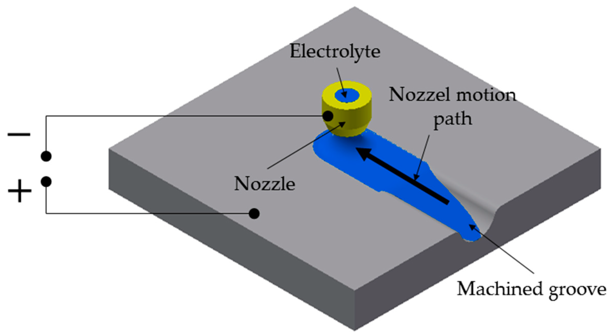
2. Materials and Methods
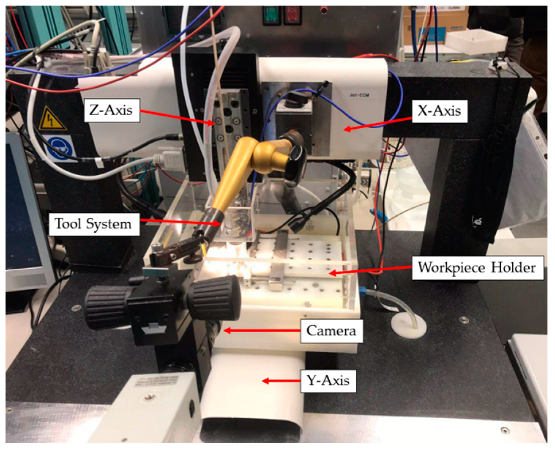
3. Experimental Setup
Design of Experiments
4. Results
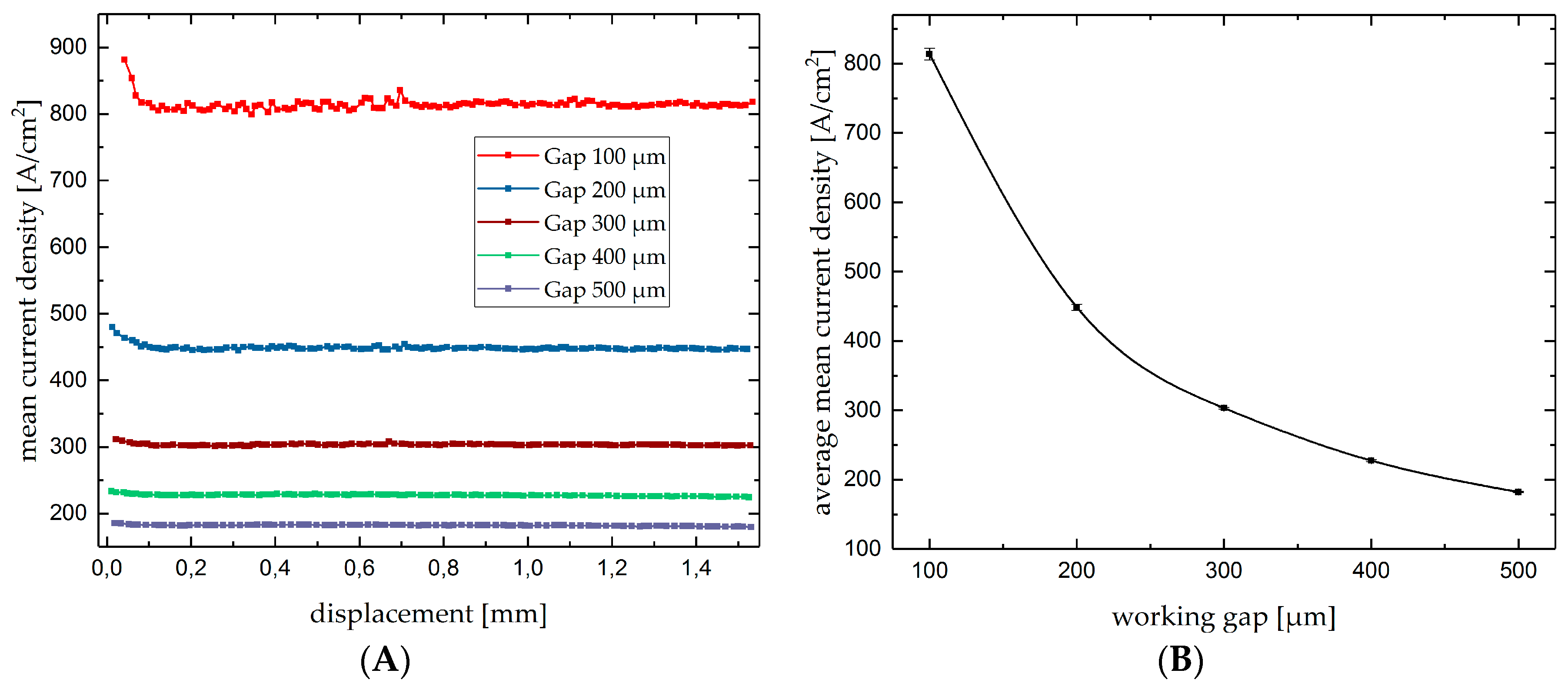
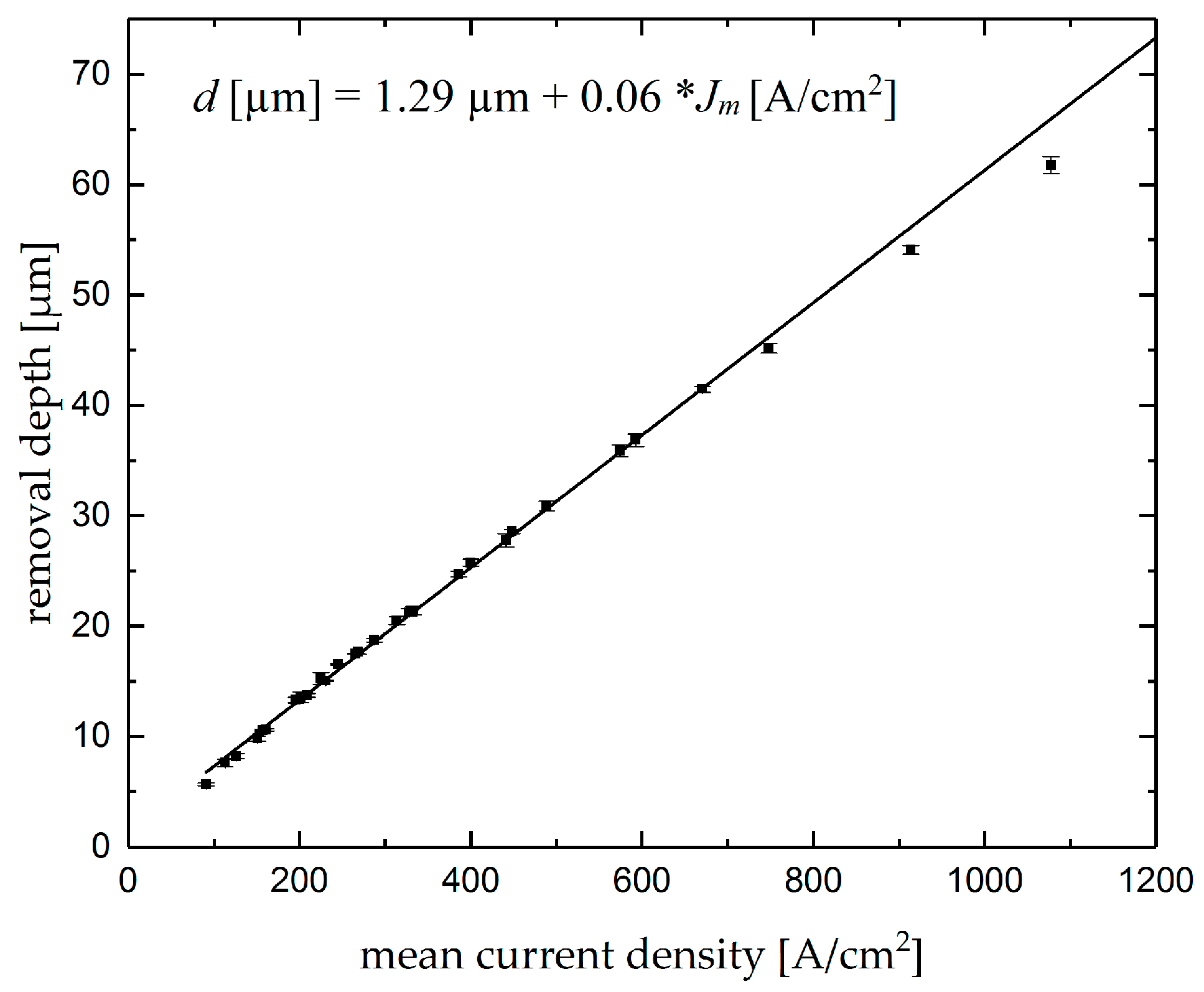
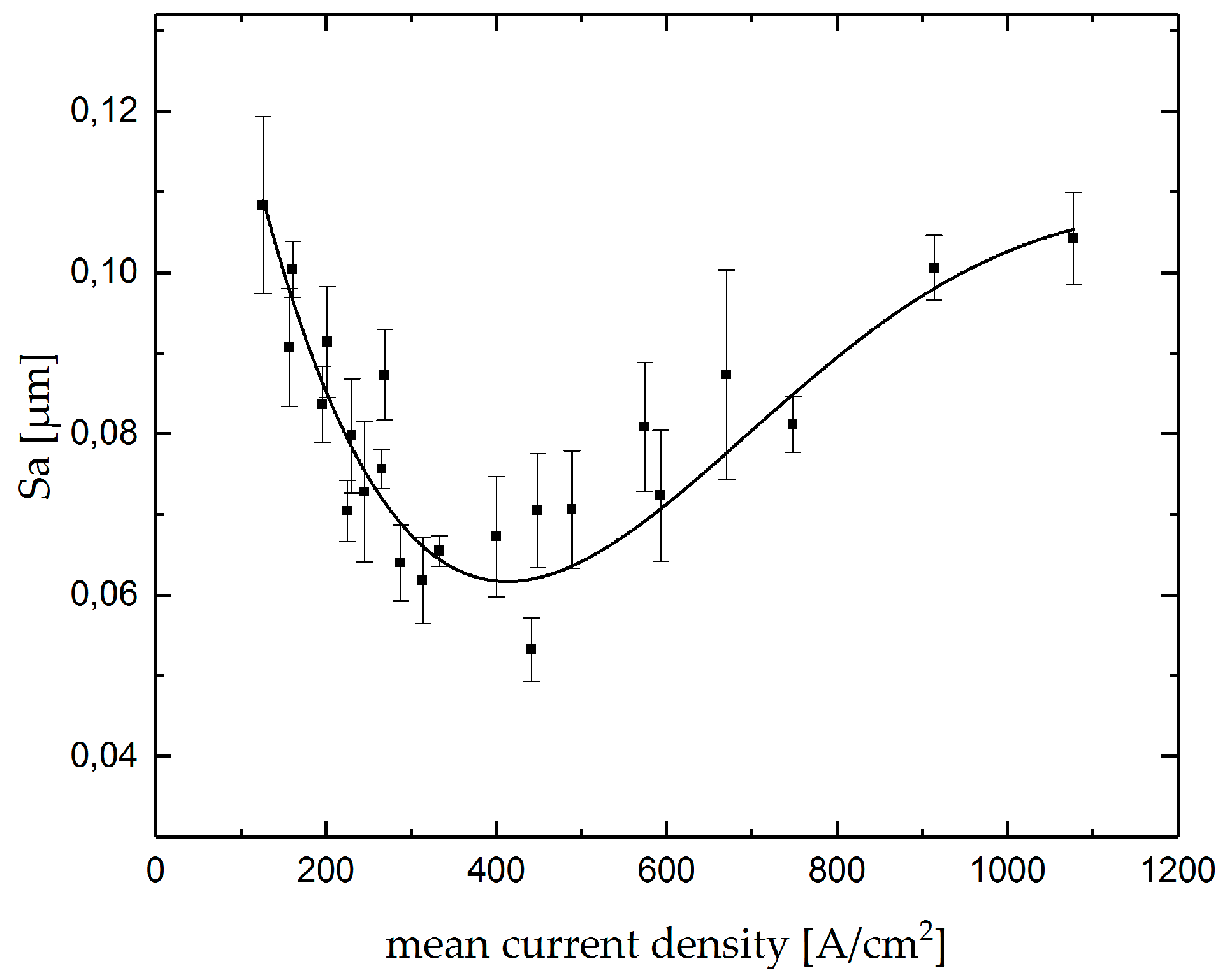
4.1. Single Grooves
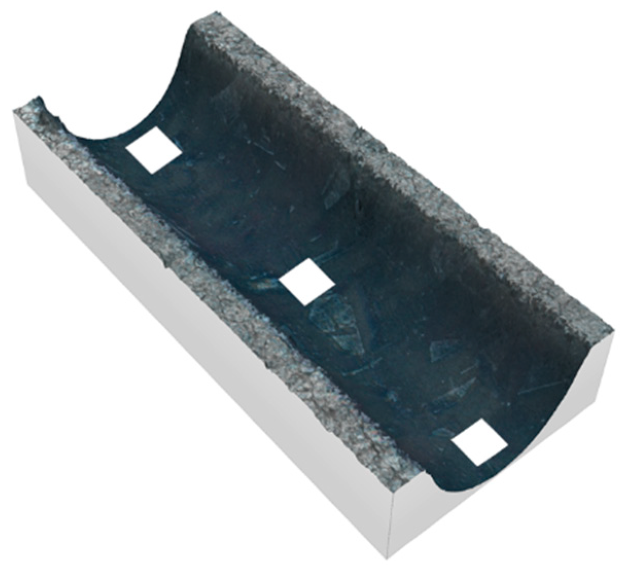
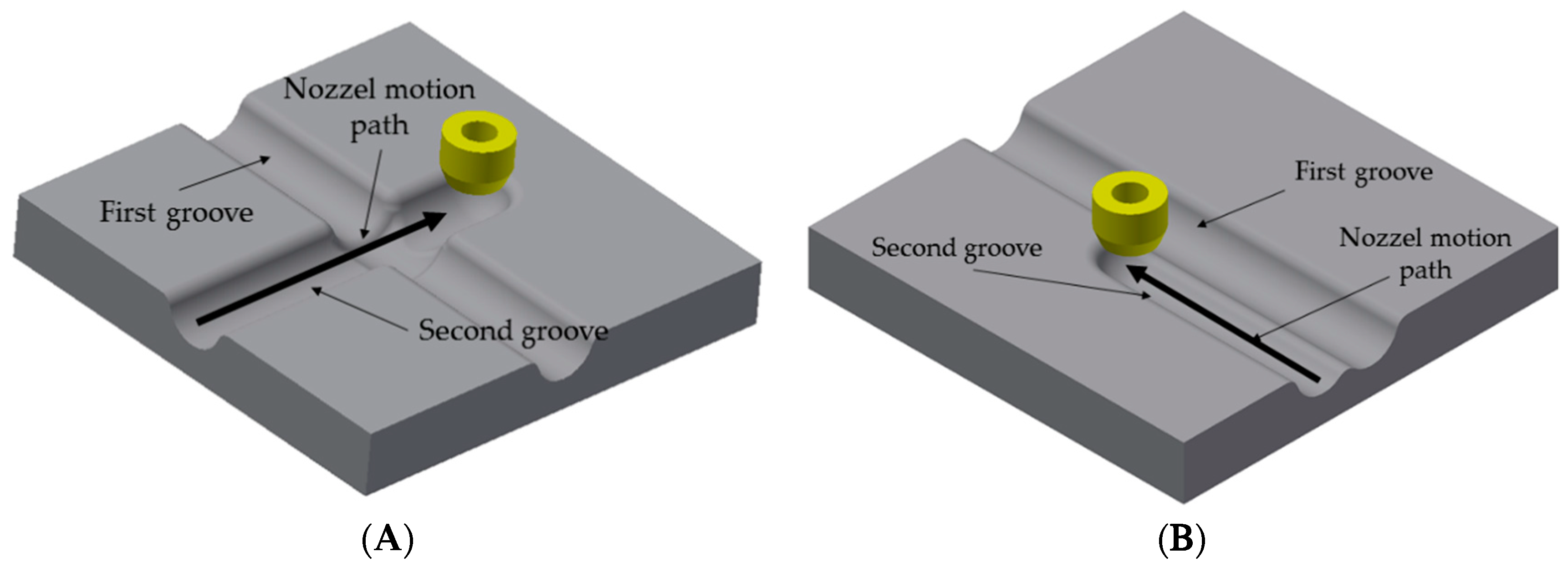
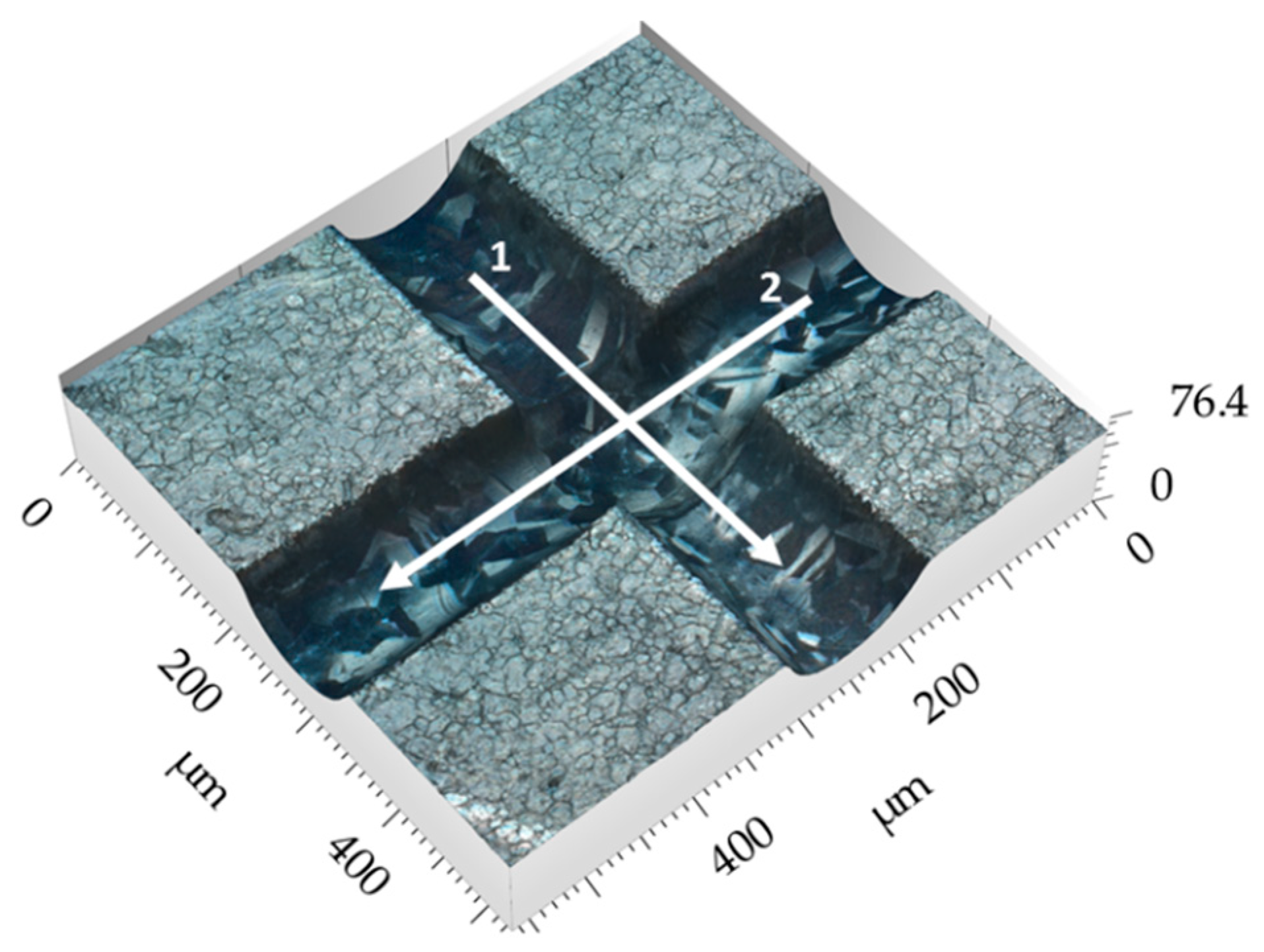
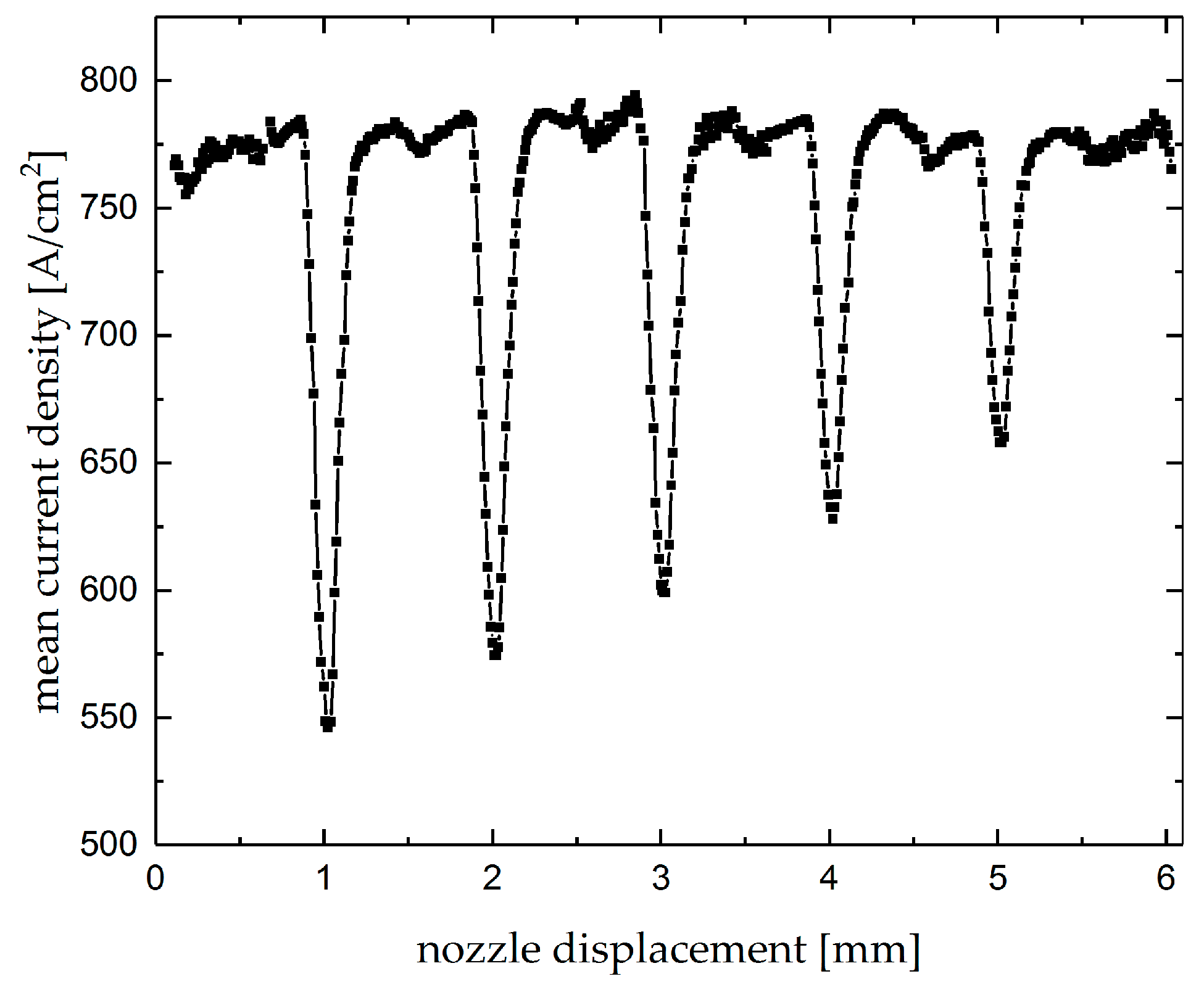
4.2. Intersecting Grooves
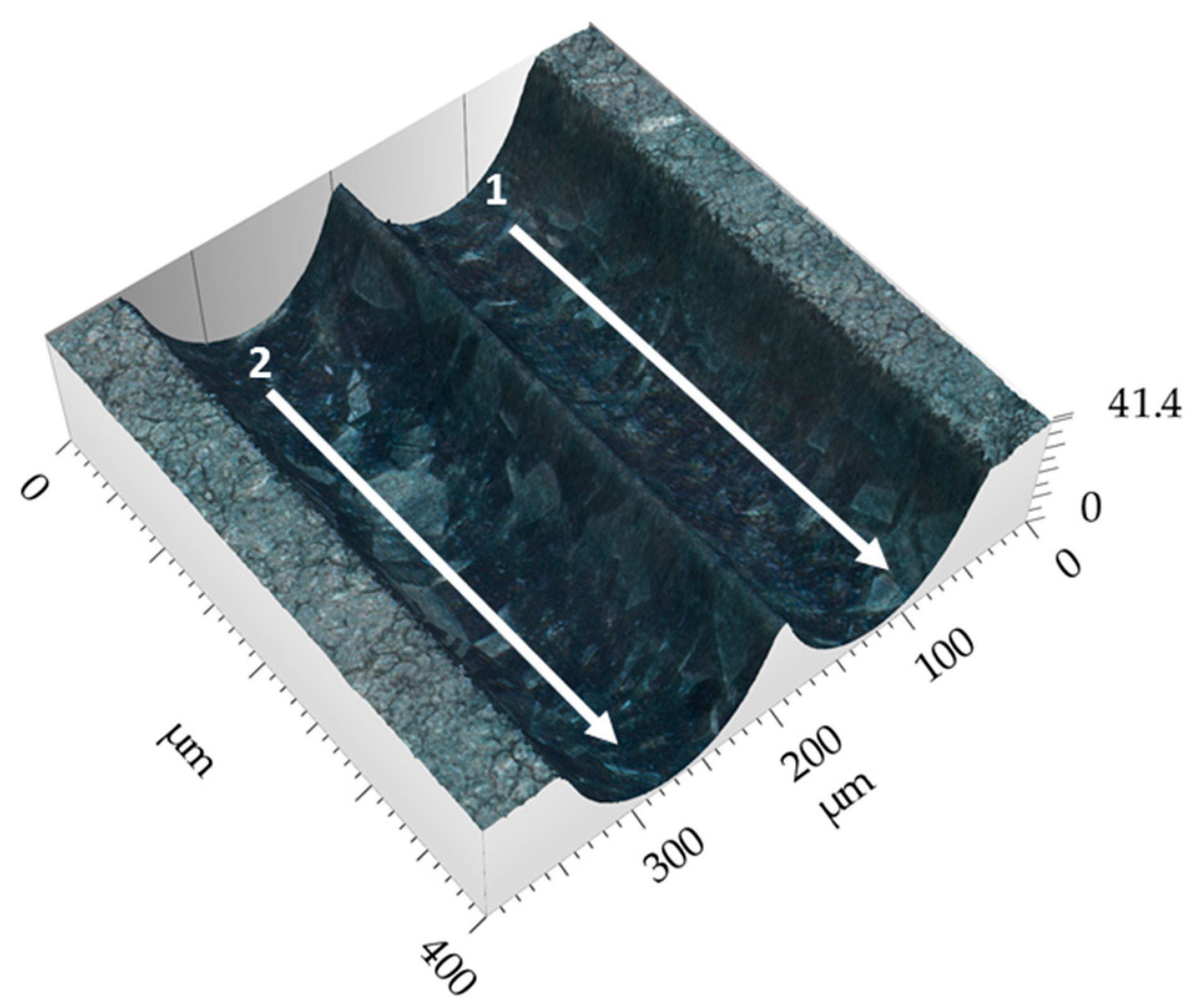
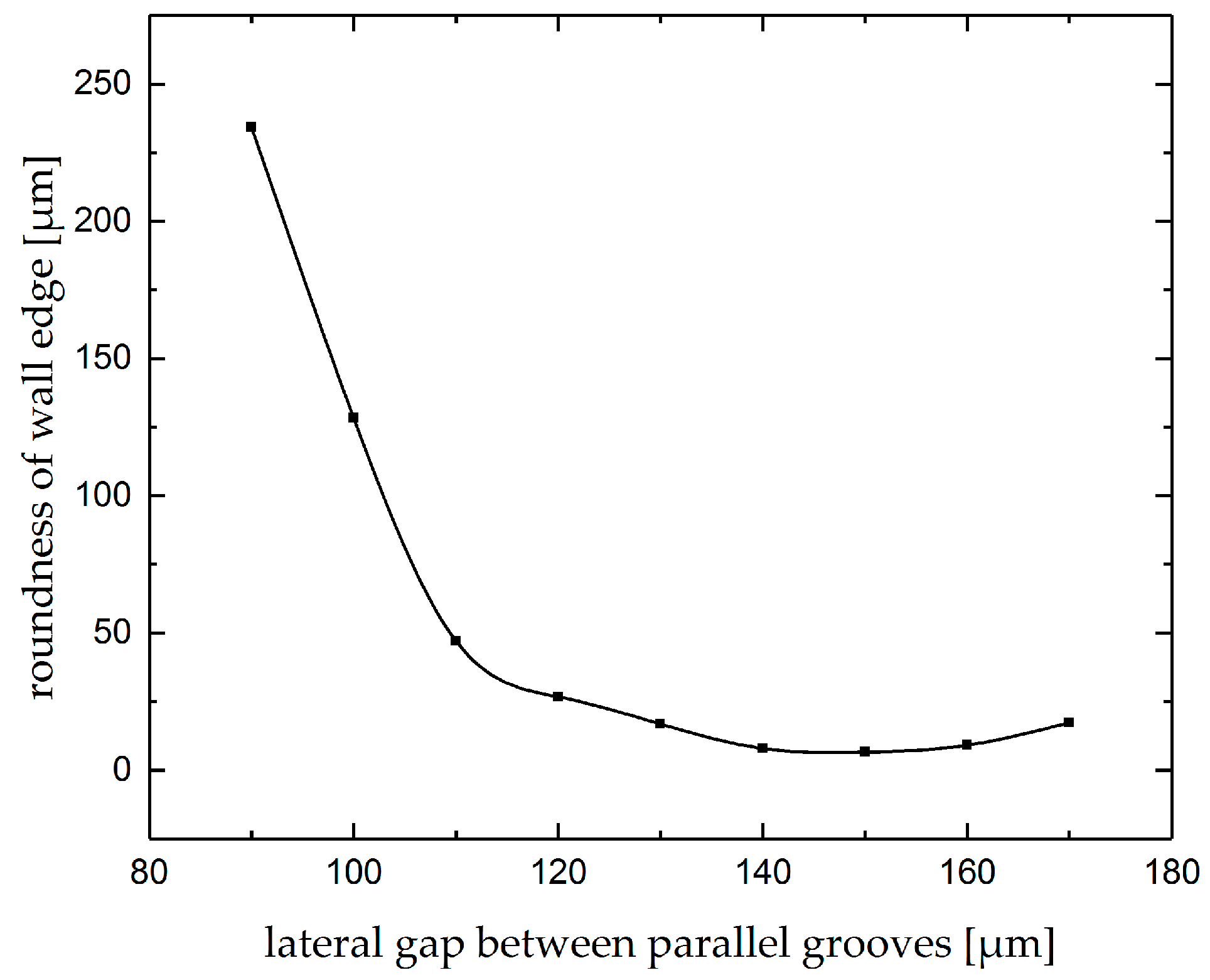
4.3. Parallel Grooves
5. Conclusions
- depth changes linearly with current density and
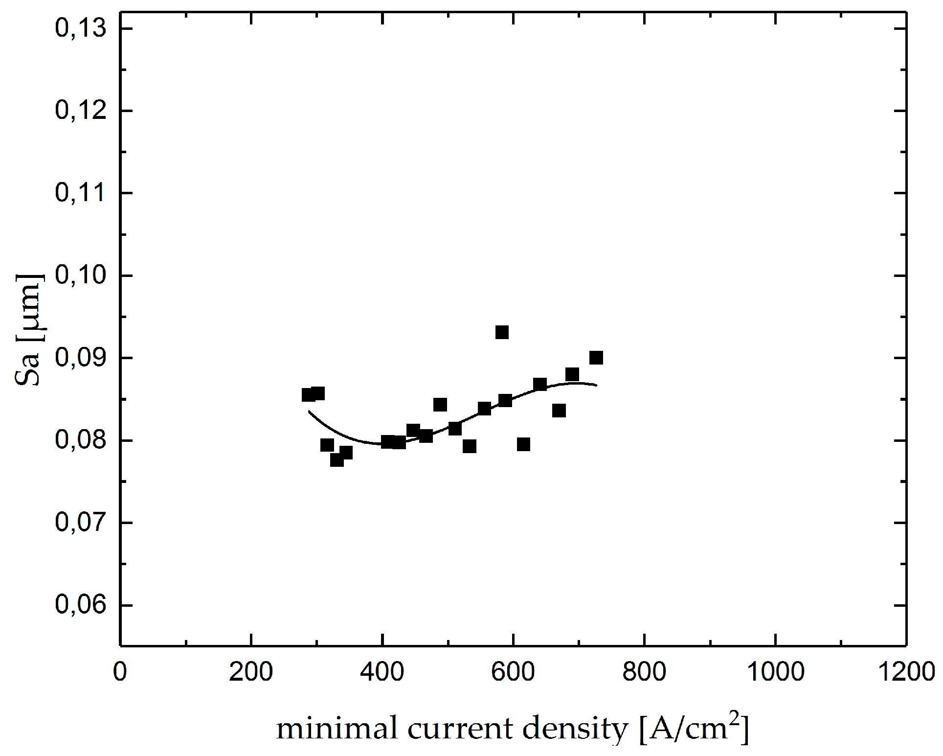
- surface roughness decreases with the increase in current density and then increases again.
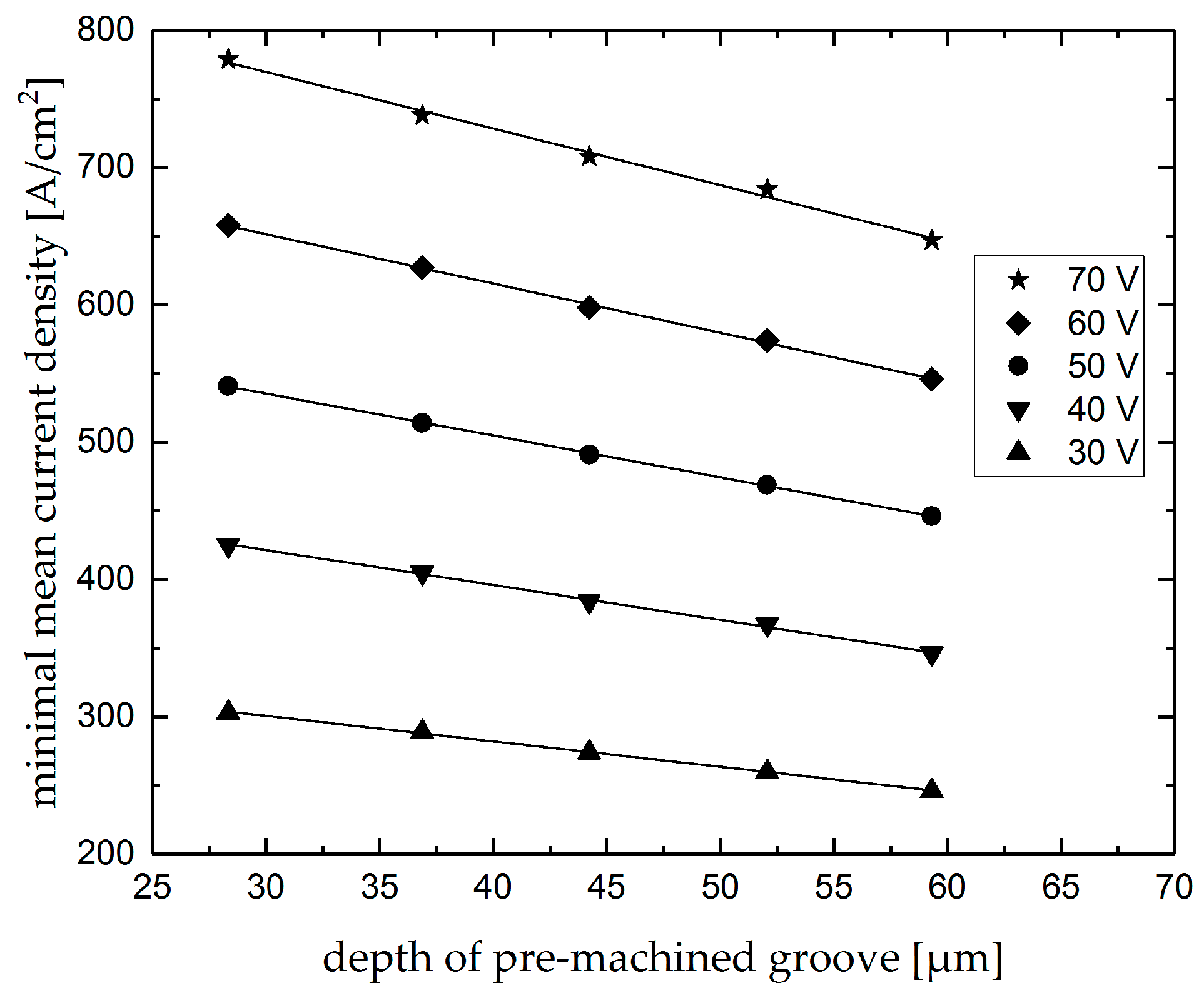
- minimum current density over intersections changes proportionally to the depth of premachined grooves for each machining voltage level, which can be used as a monitoring tool for the first groove depth;
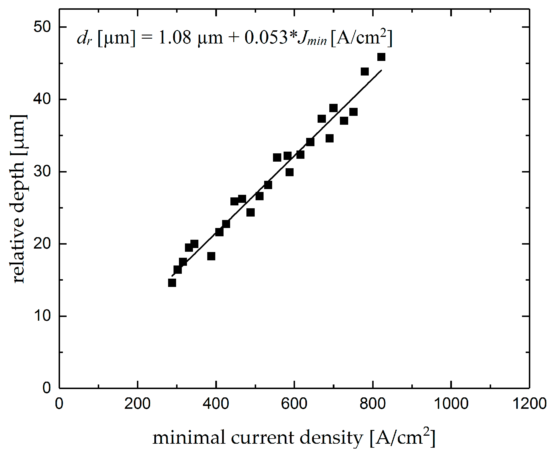
- the relative depth of intersections showed linear changes with the minimum current density over the intersection. Therefore, minimum depth over intersection can be applied for the prediction of the relative depth; and
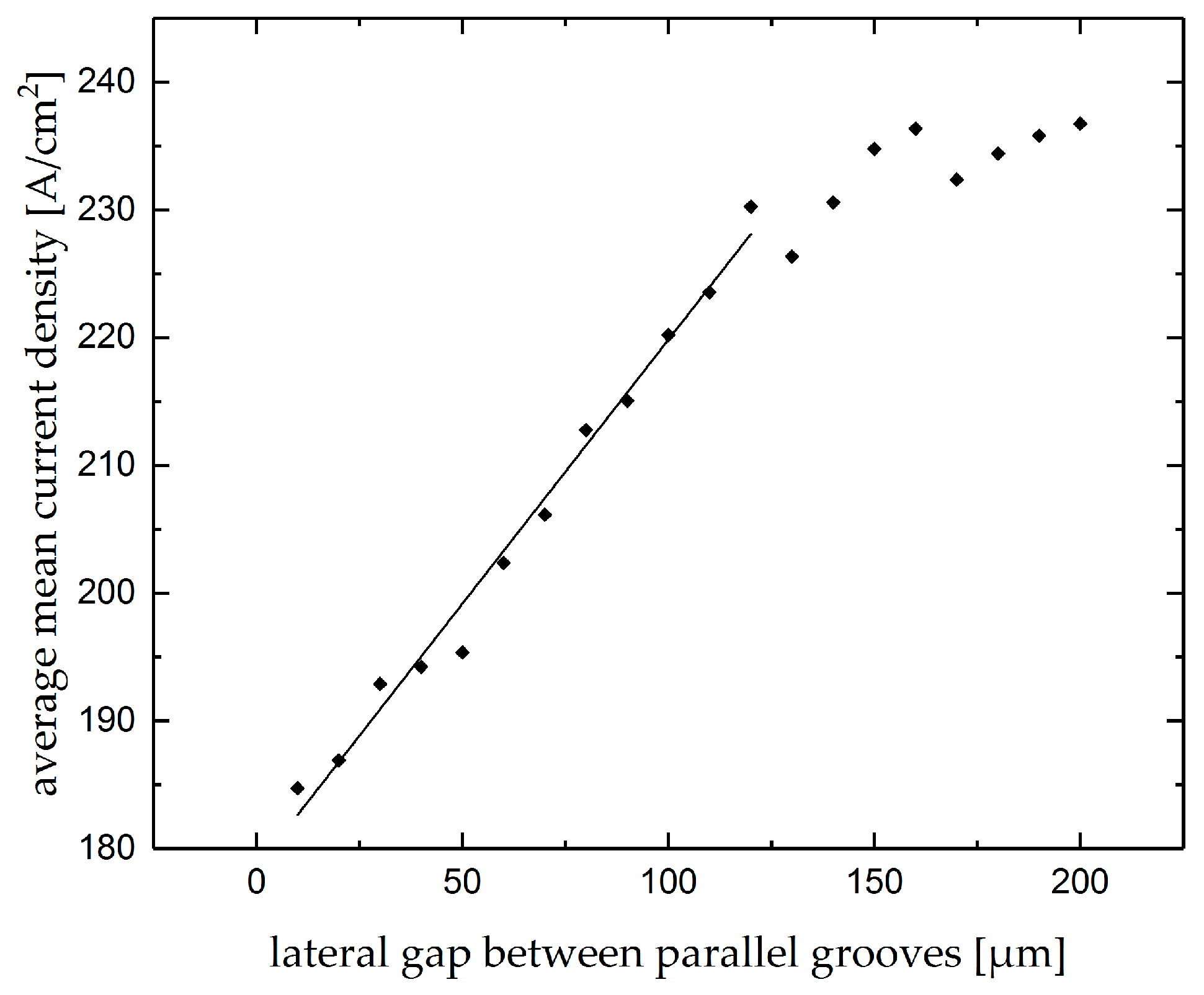
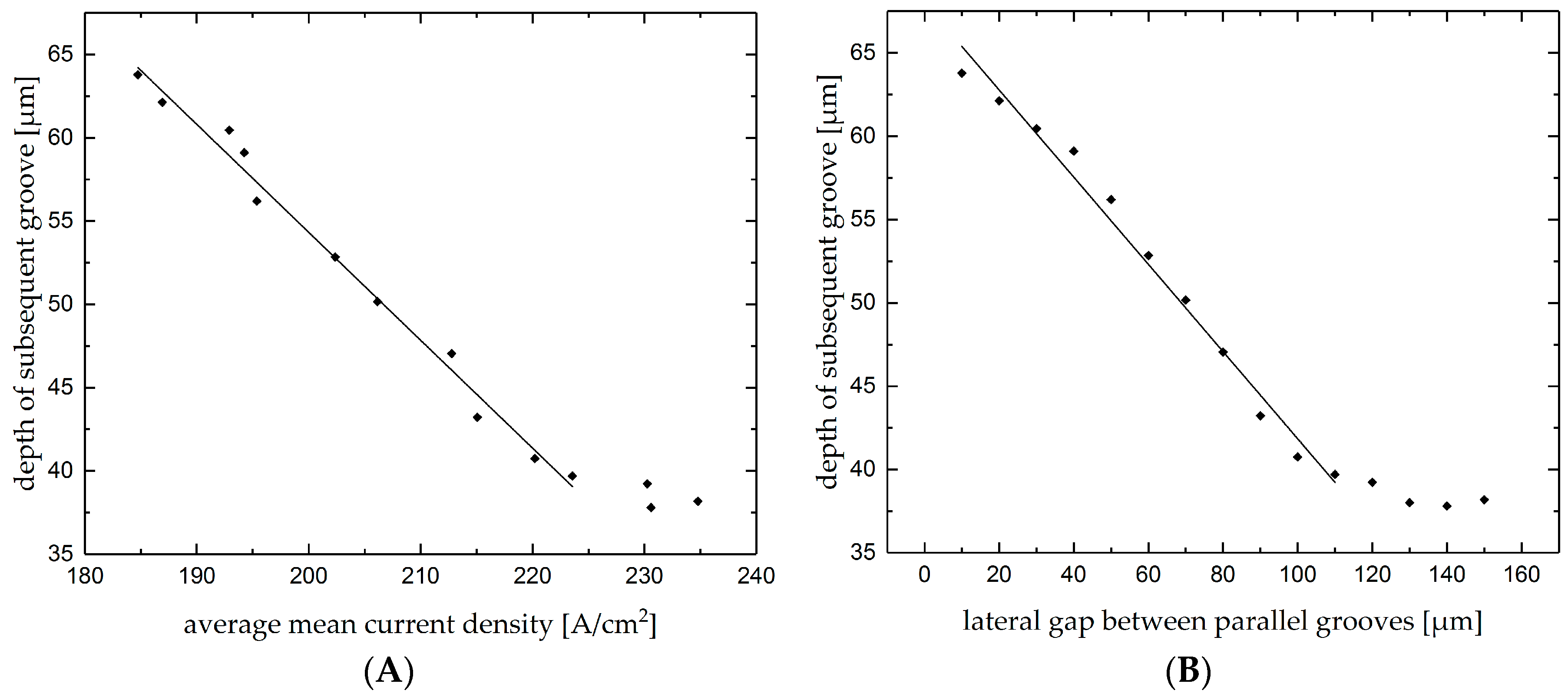
- the depth and the mean current density of subsequent parallel grooves changes linearly with the lateral gap. This enhance the process monitoring with useful data of the actual lateral gap as well as the depth by monitoring the mean current density.
Author Contributions
Funding
Acknowledgments
Conflicts of Interest
References
- Schubert, A.; Hackert-Oschätzchen, M.; Martin, A.; Winkler, S.; Kuhn, D.; Meichsner, G.; Zeidler, H.; Edelmann, J. Generation of Complex Surfaces by Superimposed Multi-dimensional Motion in Electrochemical Machining. Procedia CIRP 2016, 42, 384–389. [Google Scholar] [CrossRef]
- Schubert, A.; Hackert-Oschätzchen, M.; Meichsner, G.; Zinecker, M.; Edelmann, J. Precision and Micro ECM with Localized Anodic Dissolution. In Proceedings of the 8th International Conference on Industrial Tools and Material Processing Technologies, Ljubljana, Slovenia, 2–5 October 2011; pp. 193–196. [Google Scholar]
- Hackert, M. Entwicklung und Simulation eines Verfahrens zum elektrochemischen Abtragen von Mikrogeometrien mit geschlossenem elektrolytischen Freistrahl; Scripts Precision and Microproduction Engineering, Band 2; Schubert, A., Ed.; Verlag Wissenschaftliche Scripten: Auerbach, Germany, 2010; ISBN 9783937524955. [Google Scholar]
- Schubert, A.; Hackert-Oschätzchen, M.; Meichsner, G.; Zinecker, M.; Martin, A. Evaluation of the Influence of the Electric Potential in Jet Electrochemical Machining. In Proceedings of the 7th International Symposium on Electrochemical Machining Technology, Wien, Austria, 3–4 November 2011; pp. 47–54. [Google Scholar]
- Hackert-Oschätzchen, M.; Martin, A.; Meichsner, G.; Schubert, A. Evaluation of Gap Control Strategies in Jet Electrochemical Machining on Defined Shape Deviations. In Proceedings of the 10th International Symposium on Electrochemical Machining Technology, Saarbrücken, Germany, 13–14 November 2014; pp. 23–25. [Google Scholar]
- Mitchell-Smith, J.; Speidel, A.; Clare, A.T. Advancing electrochemical jet methods through manipulation of the angle of address. J. Mater. Process. Technol. 2018, 255, 364–372. [Google Scholar] [CrossRef]
- Goel, H.; Pandey, P.M.; Delhi, I.I.T.; Delhi, I.I.T. Experimental investigations into micro-drilling using air assisted jet electrochemical machining. In Proceedings of the 5th International & 26th All India Manufacturing Technology, Design and Research Conference, AIMTDR, Guwahati, India, 12–14 December 2014; Volume 1, pp. 1–7. [Google Scholar]
- Hackert-Oschätzchen, M.; Meichsner, G.; Martin, A.; Zeidler, H.; Schubert, A. Fast Micromilling with Jet Electrochemical Machining. In Proceedings of the Danubia-Adria Symposium on Advances in Experimental Mechanics 2012, Belgrade, Serbia, 26–29 September 2012; pp. 54–55. [Google Scholar]
- Martin, A.; Hackert-Oschätzchen, M.; Lehnert, N.; Schubert, A. Analysis of the fundamental removal geometry in electrochemical profile turning with continuous electrolytic free jet. Procedia CIRP 2018, 68, 466–470. [Google Scholar] [CrossRef]
- Martin, A.; Hackert-Oschätzchen, M.; Lehnert, N.; Schubert, A. Analysis of the removal geometry in electrochemical straight turning with continuous electrolytic free jet. In Proceedings of the 13th International Symposium on ElectroChemical Machining Technology, Dresden, Germany, 30 November–1 December 2017; pp. 81–87. [Google Scholar]
- Kawanaka, T.; Kunieda, M. Mirror-like finishing by electrolyte jet machining. CIRP Ann. Manuf. Technol. 2015, 64, 237–240. [Google Scholar] [CrossRef]
- Hackert-Oschätzchen, M.; Kowalick, M.; Meichsner, G.; Schubert, A.; Hommel, B.; Jähn, F.; Scharrnbeck, M.; Garn, R.; Lenk, A. 2D Axisymmetric Simulation of the Electrochemical Finishing of Micro Bores by Inverse Jet Electrochemical Machining. In Proceedings of the European COMSOL Conference, Rotterdam, The Netherlands, 23–25 October 2013. [Google Scholar]
- Oschätzchen, M.H.; Martin, A.; Meichsner, G.; Kowalick, M.; Zeidler, H.; Schubert, A. Inverse jet electrochemical machining for functional edge shaping of micro bores. Procedia CIRP 2013, 6, 378–383. [Google Scholar] [CrossRef]
- Hackert-Oschätzchen, M.; Martin, A.; Meichsner, G.; Schubert, A. Analysis of strategies for gap control in jet electrochemical machining. In Proceedings of the 14th EUSPEN International Conference, Dubrovnik, Croatia, 2–6 June 2014; pp. 439–442. [Google Scholar]
- Leese, R.J. Electrochemical Machining—New Machining Targets and Adaptations with Suitability for Micromanufacturing. Ph.D. Thesis, Brunel University, London, UK, 2016. [Google Scholar]
- Schubert, A.; Hackert, M.; Meichsner, G. Simulating the Influence of the Nozzle Diameter on the Shape of Micro Geometries generated with Jet Electrochemical Machining. In Proceedings of the COMSOL Conference, Boston, MA, USA, 8–10 October 2009; pp. 2–5. [Google Scholar]
- Leese, R.J.; Ivanov, A. Electrochemical micromachining: An introduction. Adv. Mech. Eng. 2016, 8, 1–13. [Google Scholar] [CrossRef]
- Hackert-Oschätzchen, M.; Martin, A.; Meichsner, G.; Zinecker, M.; Schubert, A. Microstructuring of carbide metals applying Jet Electrochemical Machining. Precis. Eng. 2013, 37, 621–634. [Google Scholar] [CrossRef]
- Hackert, M.; Meichsner, G.; Schubert, A. Generating Micro Geometries with Air Assisted Jet Electrochemical Machining. In Proceedings of the 10th Anniversary International Conference of the European Society for Precision Engineering and Nanotechnology, EUSPEN 2008, Zürich, Switzerland, 18–22 May 2008; pp. 420–424. [Google Scholar]
- Speidel, A.; Mitchell-Smith, J.; Walsh, D.A.; Hirsch, M.; Clare, A. Electrolyte Jet Machining of Titanium Alloys Using Novel Electrolyte Solutions. Procedia CIRP 2016, 42, 367–372. [Google Scholar] [CrossRef]
- Hackert-Oschätzchen, M.; Meichsner, G.; Zeidler, H.; Zinecker, M.; Schubert, A. Micro machining of different steels with closed electrolytic free jet. AIP Conf. Proc. 2011, 1353, 1337–1343. [Google Scholar] [CrossRef]
- Speidel, A.; Mitchell-Smith, J.; Bisterov, I.; Clare, A.T. The importance of microstructure in electrochemical jet processing. J. Mater. Process. Technol. 2018, 262, 459–470. [Google Scholar] [CrossRef]
- König, W. Elektrochemisches Abtragen (ECM). In Fertigungsverfahren 3; Springer: Berlin/Heidelberg, Germany, 2007; pp. 133–185. [Google Scholar]
- Heinemann, H.; Krämer, H.; Zimmer, H. Kleine Formelsammlung Physik; Fachbuchverlag Leipzig: Leipzig, Germany, 1997. [Google Scholar]
- Lindenlauf, H.-P. Werkstoff- und Elektrolytspezifische Einflüsse auf die Elektrochemische Senkbarkeit ausgewählter Stähle und Nickellegierungen. Ph.D. Thesis, RWTH Aachen, Aachen, Germany, 1977. [Google Scholar]
- Rosenkranz, C. Elektrochemische Prozesse an Eisenoberflächen bei Extremen Anodischen Stromdichten. Ph.D. Thesis, Heinrich-Heine-Universität Düsseldorf, Düsseldorf, Germany, 2005. [Google Scholar]
- Andreatta, F.; Lohrengel, M.M.; Terryn, H.; de Wit, J.H.W. Electrochemical characterisation of aluminium AA7075-T6 and solution heat treated AA7075 using a micro-capillary cell. Electrochim. Acta 2003, 48, 3239–3247. [Google Scholar] [CrossRef]
- Haisch, T.; Mittemeijer, E.; Schultze, J.W. Electrochemical machining of the steel 100Cr6 in aqueous NaCl and NaNO3 solutions: Microstructure of surface films formed by carbides. Electrochim. Acta 2001, 47, 235–241. [Google Scholar] [CrossRef]
- Lohrengel, M.M.; Klüppel, I.; Rosenkranz, C.; Bettermann, H. Microscopic investigations of electrochemical machining of Fe in NaNO3. Electrochim. Acta 2003, 48, 3203–3211. [Google Scholar] [CrossRef]
- Rosenkranz, C.; Lohrengel, M.M.; Schultze, J.W. The surface structure during pulsed ECM of iron in NaNO3. Electrochim. Acta 2005, 50, 2009–2016. [Google Scholar] [CrossRef]
- Schreiber, A.; Schultze, J.W.; Lohrengel, M.M.; Kármán, F.; Kálmán, E. Grain dependent electrochemical investigations on pure iron in acetate buffer pH 6.0. Electrochim. Acta 2006, 51, 2625–2630. [Google Scholar] [CrossRef]
- Hackert-Oschätzchen, M.; Meichsner, G.; Zinecker, M.; Martin, A.; Schubert, A. Micro machining with continuous electrolytic free jet. Precis. Eng. 2012, 36, 612–619. [Google Scholar] [CrossRef]


| Parameter | Value | |||||||||
|---|---|---|---|---|---|---|---|---|---|---|
| Workpiece Material | Co [18] | WC [18] | WC- 6% Co [18] | Nimonic 80A [19] | Ti-6Al-4V [20] | EN 1.2379 [21] | EN 1.4301 [21] | EN 1.4541 [21] | EN 1.5920 [21] | Brass, Cu39Zn2Pb [22] |
| Nozzle inner diameter (µm) | 100 | 100 | 100 | 100 | 250 | 100 | 510 | |||
| Electrolyte | 20% NaCl | 20% NaCl | 20% NaCl | 20% NaCl | 2–4 M NaNO3 | 30% NaNO3 | 2.3 M NaNO3 | |||
| Working gap (µm) | 100 | 100 | 100 | 100 | 500 | 100 | 500 | |||
| Voltage (V) | 50 | 50 | 10–55 | 1–56 | - | 56 | - | |||
| Nozzle speed (µm/s) | 200 | 200 | 200 | 150 | 0 Machining time: 10s | 200–1000 | 500 | |||
| Depth of removal (µm) | 40 | < 1 | 4–5 | 300 | 50–250 | 75–240 | 60–230 | 60–220 | 100–250 | 150 µm/C |
| Surface roughness (µm) | - | - | Ra < 0.65 | - | - | 0.35 < Ra < 0.45 | 0.1 < Ra < 0.15 | 0.15 < Ra < 0.33 | 0.3 < Ra < 0.45 | 0.3 < Sa < 1.5 |
| Parameter | Value | |
|---|---|---|
| Workpiece material | EN 1.4301 | |
| Nozzle inner diameter | 100 µm | |
| Electrolyte | 30% NaNO3 | |
| Electrolyte supply rate | 10 mL/min | |
| Working gap | single grooves | 100, 200, 300, 400, and 500 µm |
| intersecting grooves | 100 µm | |
| parallel grooves | 100 µm | |
| Voltage | single grooves | 30, 40, 50,60, 70, 80, and 90 V |
| intersecting grooves | 30, 40, 50, 60, and 70 V | |
| parallel grooves | 60 V | |
| Nozzle speed | 200 µm/s | |
| Process and Geometry Parameter | Value | ||||
|---|---|---|---|---|---|
| Machining voltage (V) | 70 | 60 | 50 | 40 | 30 |
| Depth of groove (µm) | 59 | 52 | 44 | 36 | 28 |
© 2019 by the authors. Licensee MDPI, Basel, Switzerland. This article is an open access article distributed under the terms and conditions of the Creative Commons Attribution (CC BY) license (http://creativecommons.org/licenses/by/4.0/).
Share and Cite
Yahyavi Zanjani, M.; Hackert-Oschätzchen, M.; Martin, A.; Meichsner, G.; Edelmann, J.; Schubert, A. Process Control in Jet Electrochemical Machining of Stainless Steel through Inline Metrology of Current Density. Micromachines 2019, 10, 261. https://doi.org/10.3390/mi10040261
Yahyavi Zanjani M, Hackert-Oschätzchen M, Martin A, Meichsner G, Edelmann J, Schubert A. Process Control in Jet Electrochemical Machining of Stainless Steel through Inline Metrology of Current Density. Micromachines. 2019; 10(4):261. https://doi.org/10.3390/mi10040261
Chicago/Turabian StyleYahyavi Zanjani, Matin, Matthias Hackert-Oschätzchen, André Martin, Gunnar Meichsner, Jan Edelmann, and Andreas Schubert. 2019. "Process Control in Jet Electrochemical Machining of Stainless Steel through Inline Metrology of Current Density" Micromachines 10, no. 4: 261. https://doi.org/10.3390/mi10040261