MEMS Gyroscope Temperature Compensation Based on Drive Mode Vibration Characteristic Control


Abstract
:1. Introduction
2. Dual-Mass MEMS Gyroscope
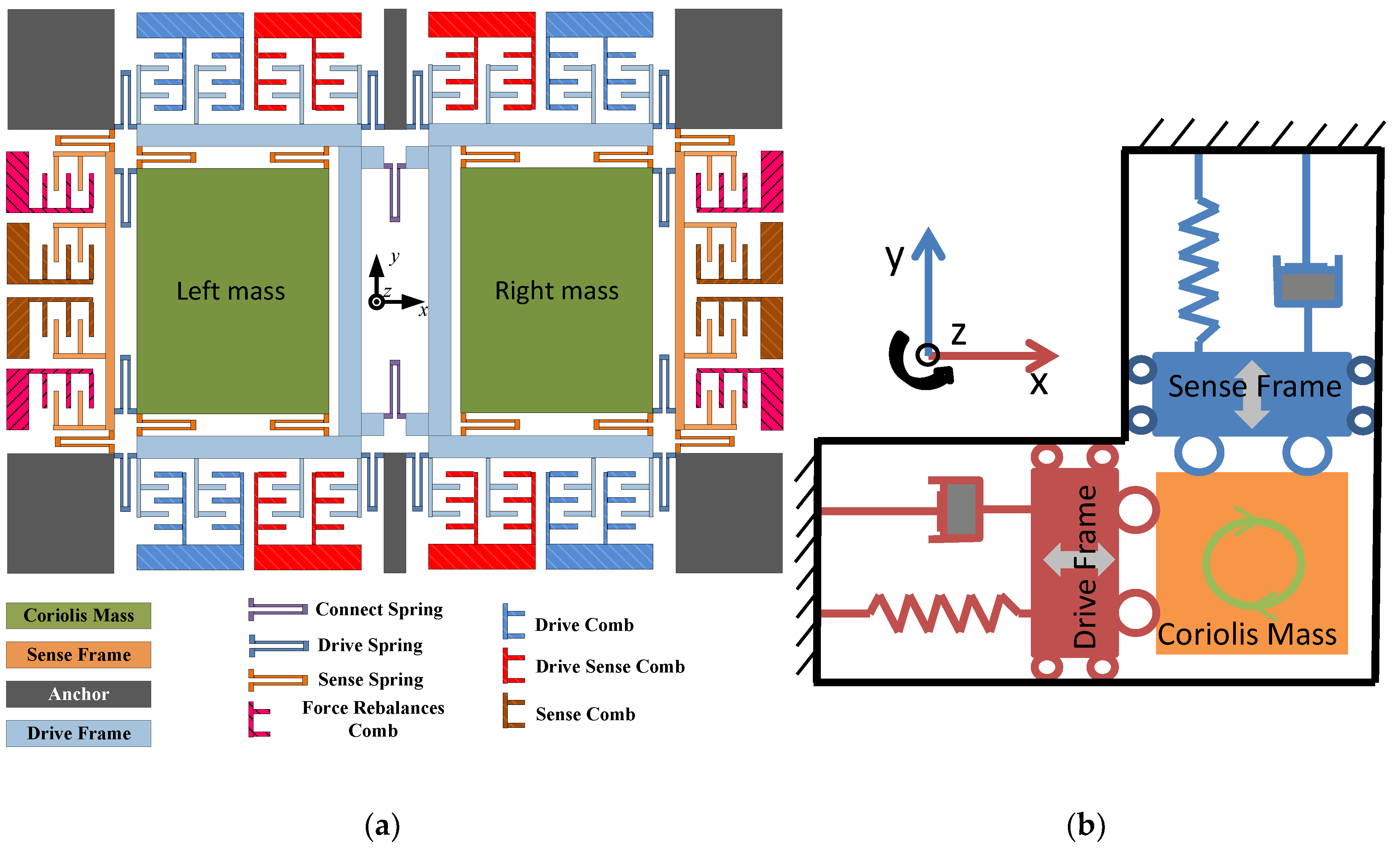
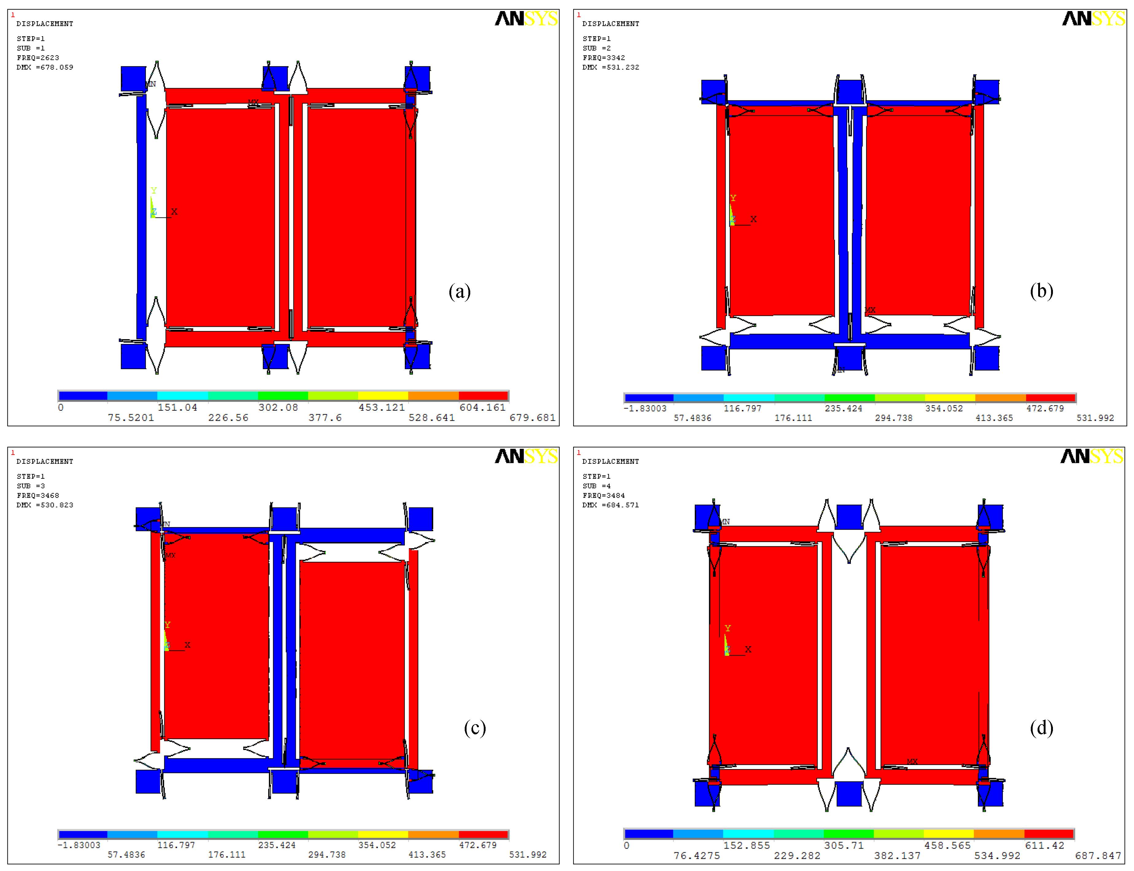
2.1. Dual-Mass MEMS Gyroscope Structure
2.2. Dual-Mass MEMS Gyroscope Structure Working Principle
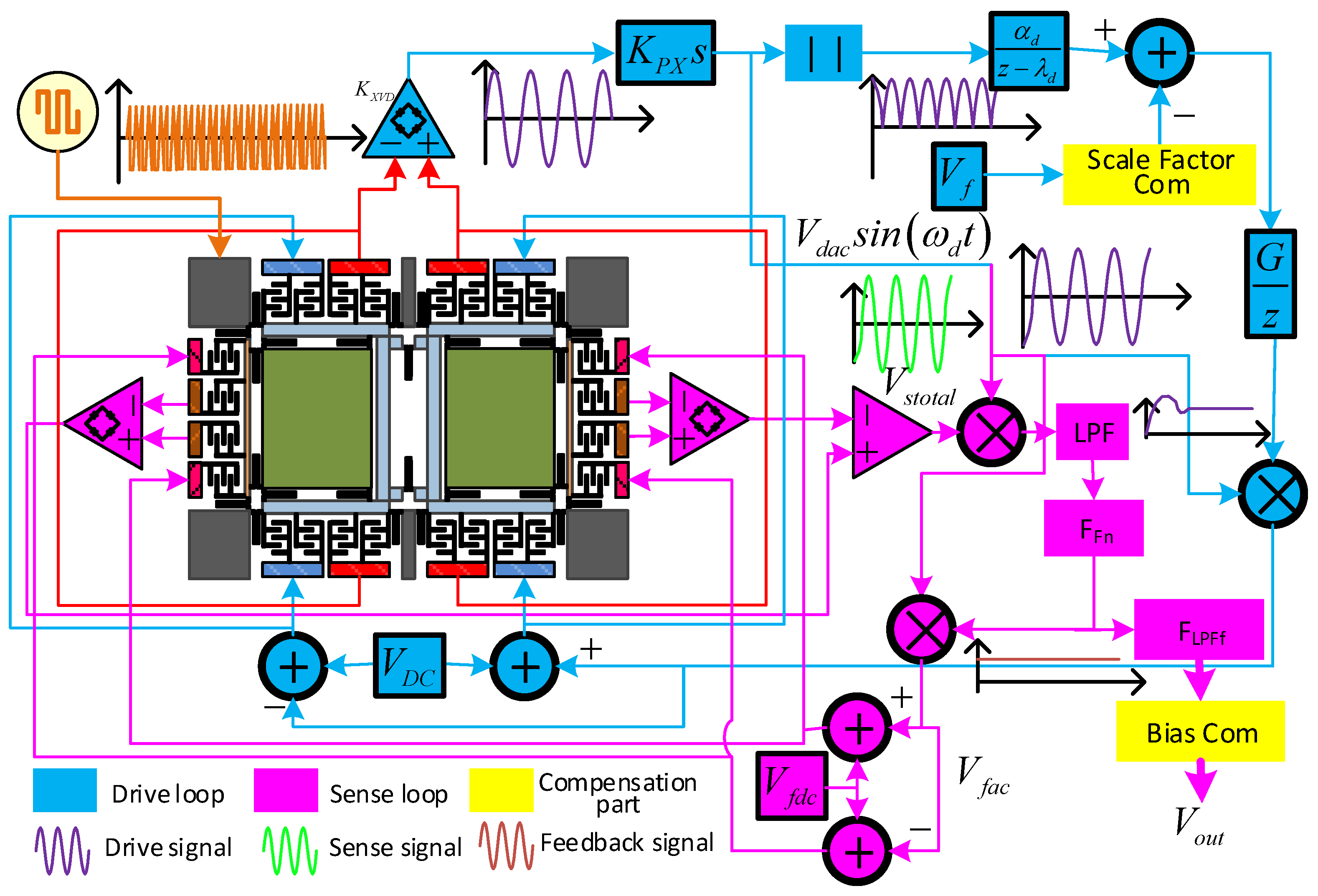
2.3. Dual-Mass MEMS Gyroscope Monitoring System
3. Temperature Compensation Method Based on Drive Mode Vibration Characteristic Control
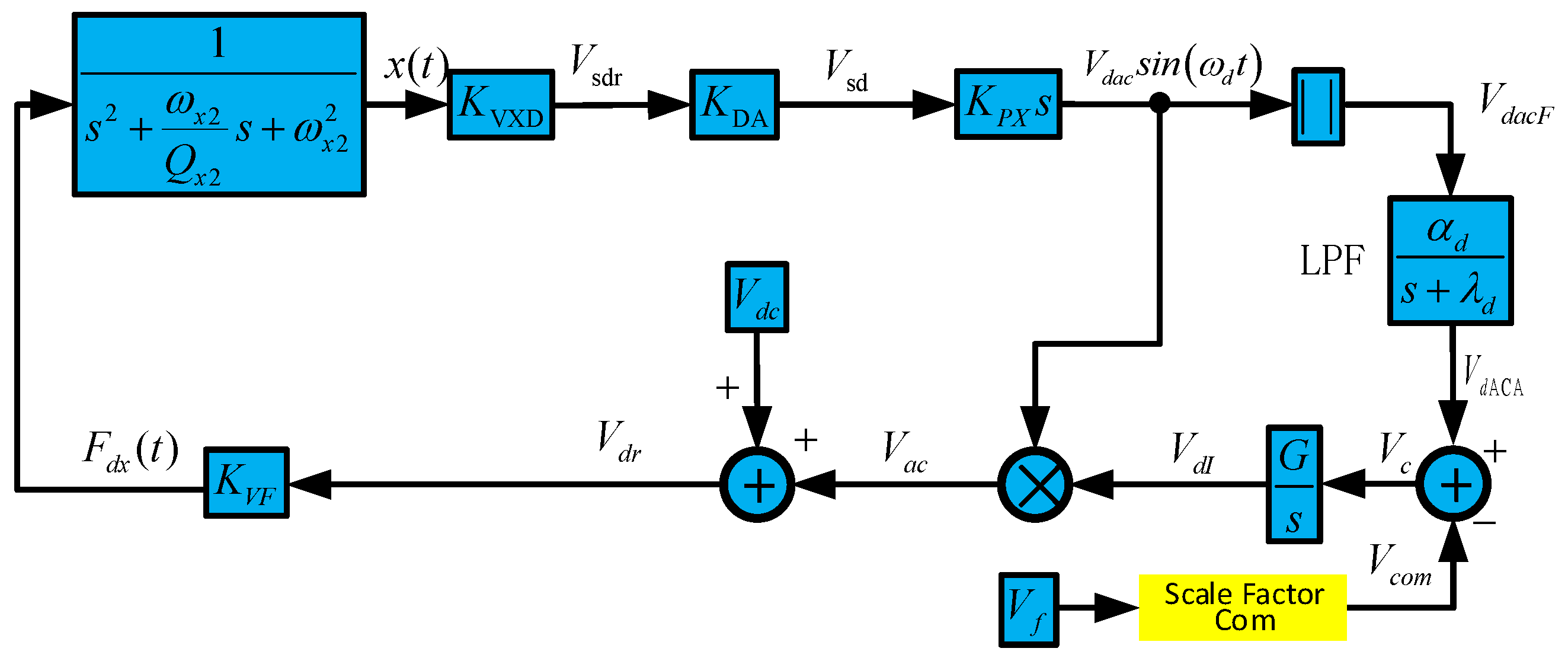
3.1. Dual-Mass MEMS Gyroscope Drive Mode Vibration Control System
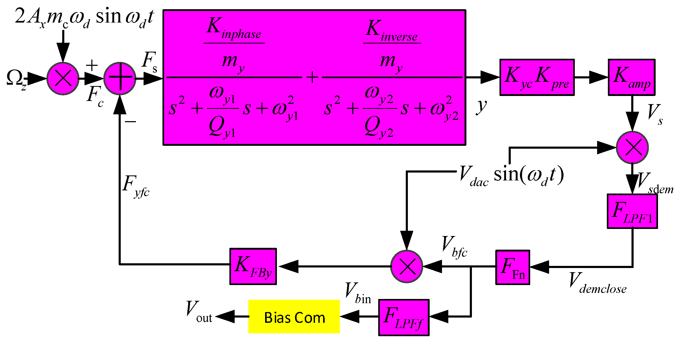
3.2. Dual-Mass MEMS Gyroscope Sense Mode Closed-loop System
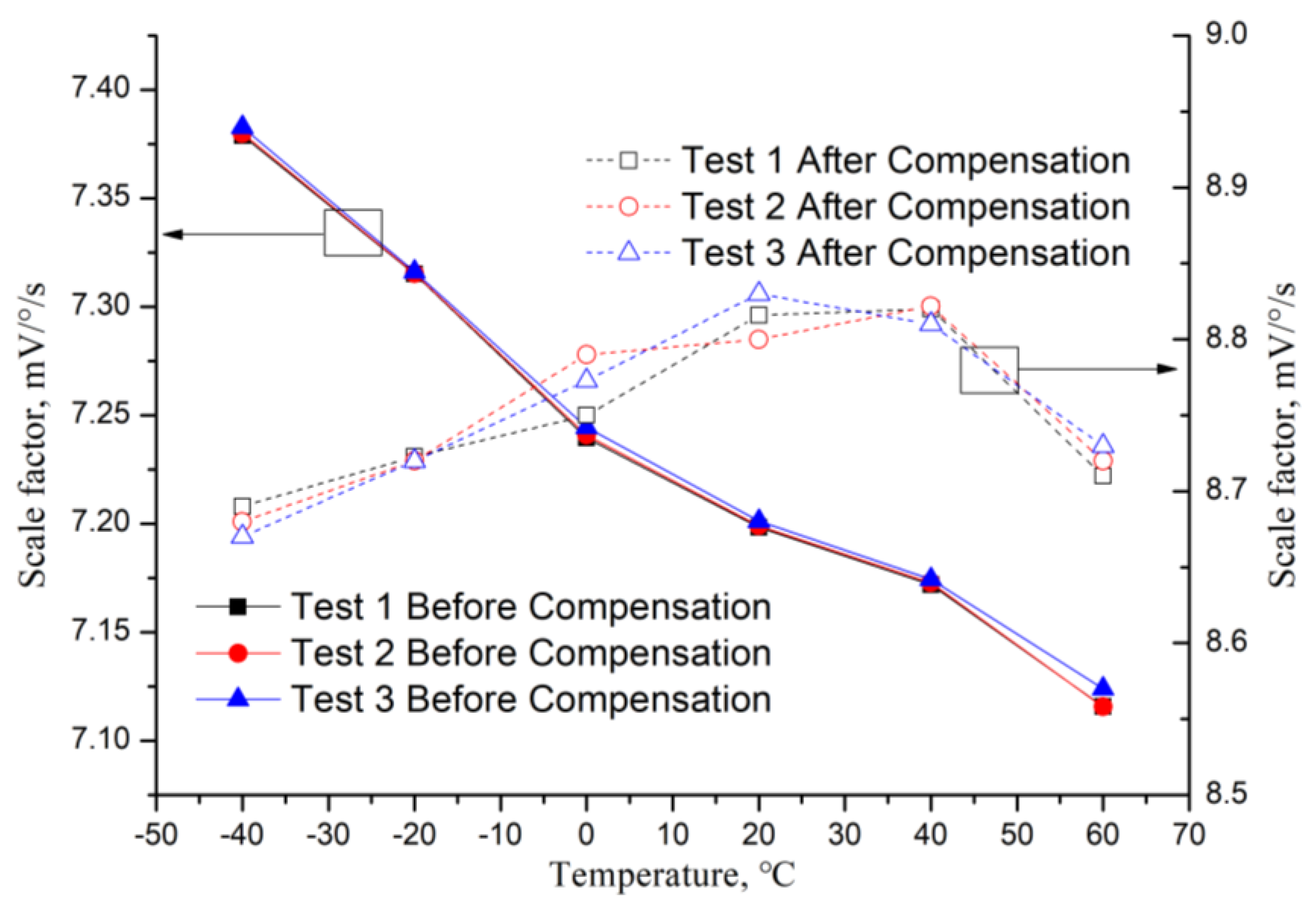
3.3. Scale Factor Temperature Compensation
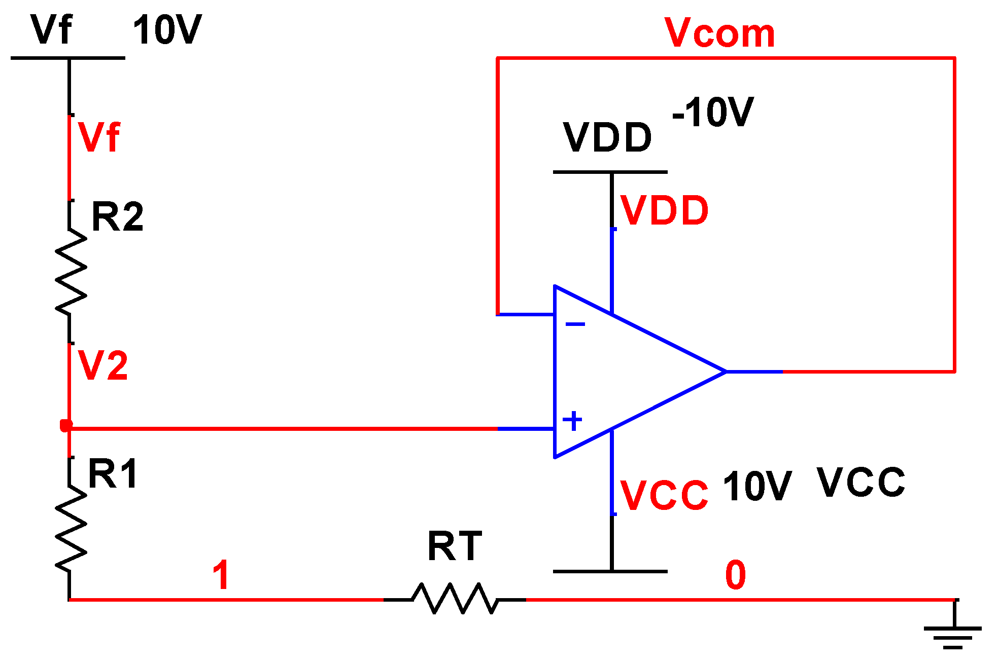
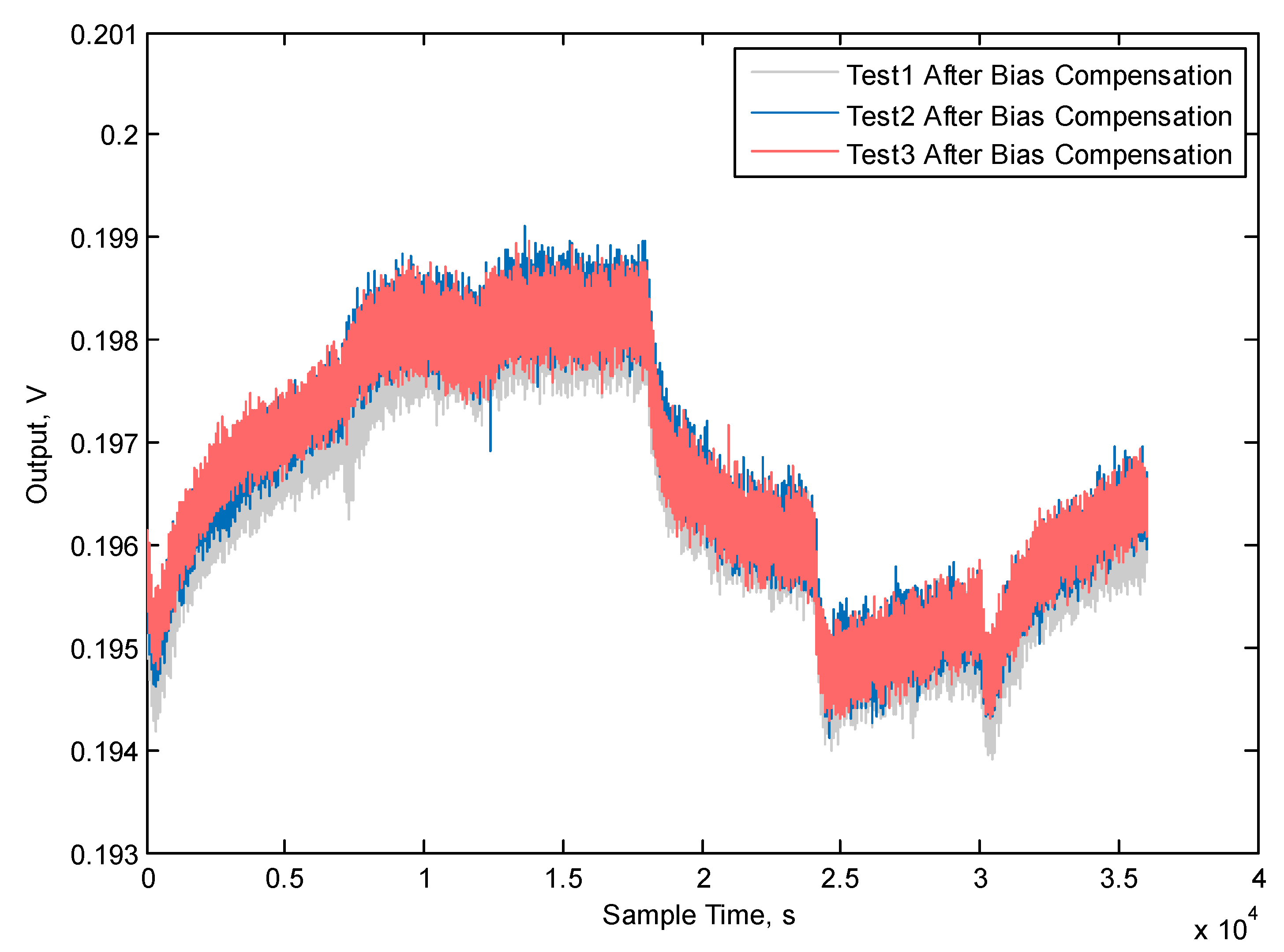
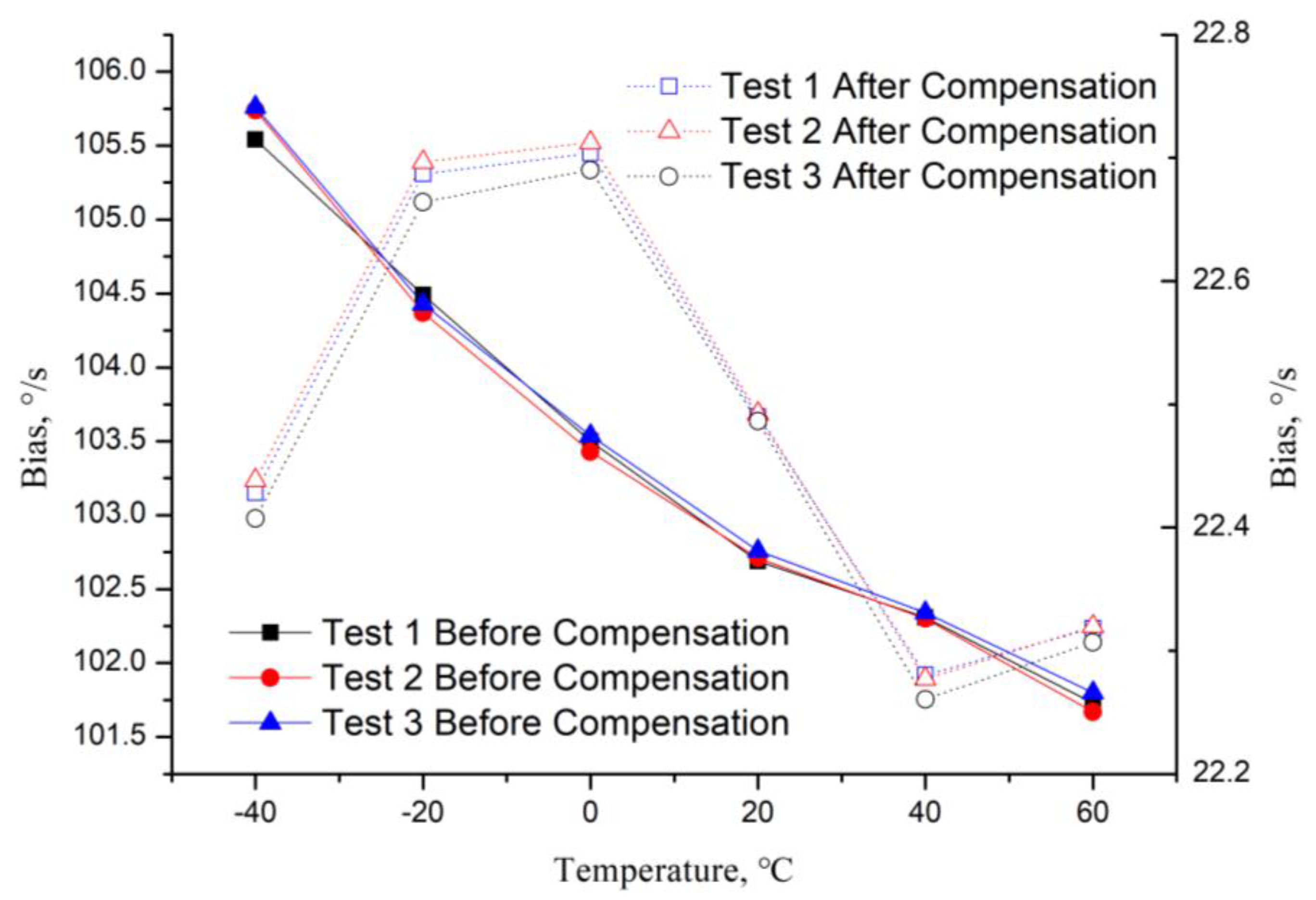
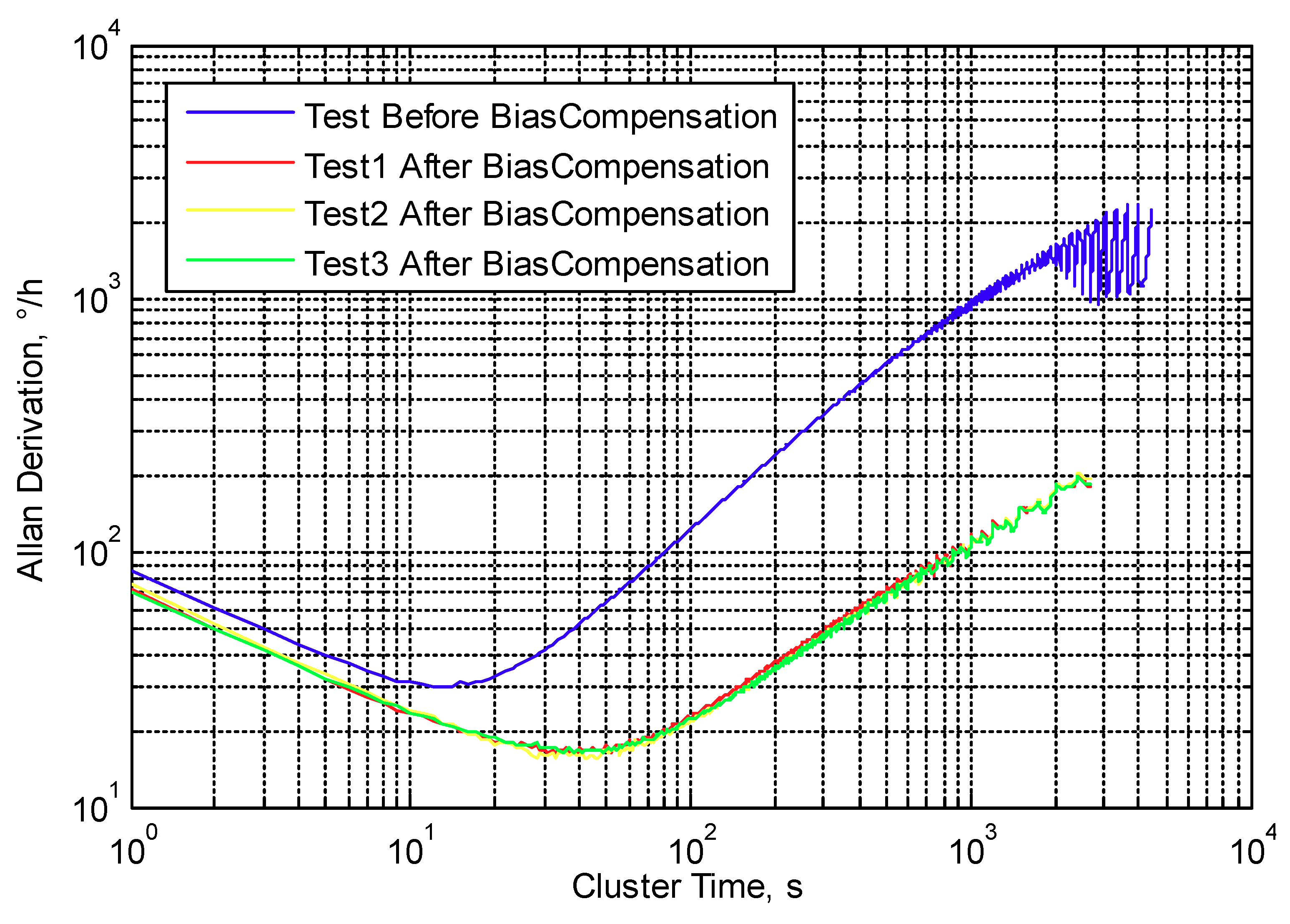
3.4. Temperature Bias Compensation
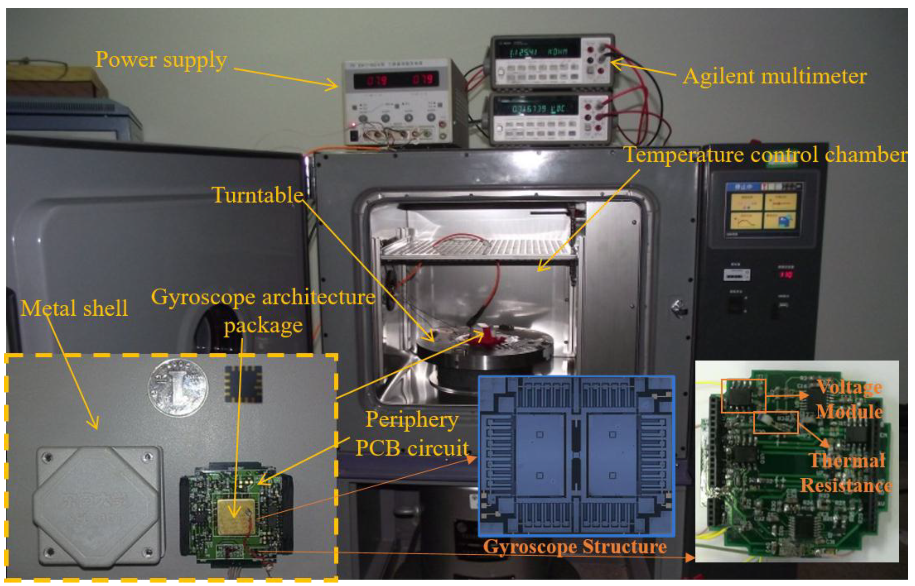
4. Temperature Compensation Experiments
5. Conclusions
Author Contributions
Funding
Conflicts of Interest
References
- Cao, H.; Liu, Y.; Zhang, Y.; Shao, X.; Gao, J.; Huang, K.; Shi, Y.; Tang, J.; Shen, C.; Liu, J. Design and Experiment of Dual-mass MEMS Gyroscope Sense Closed System Based on Bipole Compensation Method. IEEE Access. 2019. [Google Scholar] [CrossRef]
- Cao, H.; Liu, Y.; Kou, Z.; Zhang, Y.; Shao, X.; Gao, J.; Huang, K.; Shi, Y.; Tang, J.; Shen, C.; et al. Design, Fabrication and Experiment of Double U-Beam MEMS Vibration Ring Gyroscope. Micromachines 2019, 10, 186. [Google Scholar] [CrossRef] [PubMed]
- Guo, Z.; Fu, P.; Liu, D.; Huang, M. Design and FEM simulation for a novel resonant silicon MEMS gyroscope with temperature compensation function. Microsyst. Technol. 2018, 24, 1453–1459. [Google Scholar] [CrossRef]
- Tsai, N.C.; Sue, C.Y. Compensation to imperfect fabrication and asymmetry of micro-gyroscopes by using disturbance estimator. Microsyst. Technol. 2009, 15, 1803–1814. [Google Scholar] [CrossRef]
- Zhang, Y.; Wu, Y.; Xu, X.; Xi, X.; Wu, X. Research on the method to improve the vibration stability of vibratory cylinder gyroscopes under temperature variation. Int. J. Precis. Eng. Manuf. 2017, 18, 1813–1819. [Google Scholar] [CrossRef]
- Hou, Z.; Xiao, D.; Wu, X.; Su, J.; Chen, Z.; Zhang, X. Effect of die attachment on key dynamical parameters of micromachined gyroscopes. Microsyst. Technol. 2012, 18, 507–513. [Google Scholar] [CrossRef]
- Tatar, E.; Mukherjee, T.; Fedder, G.K. Stress Effects and Compensation of Bias Drift in a MEMS Vibratory-Rate Gyroscope. J. Microelectromech. Syst. 2017, 26, 569–579. [Google Scholar] [CrossRef]
- Trusov, A.A.; Schofield, A.R.; Shkel, A.M. Performance characterization of a new temperature-robust gain-bandwidth improved MEMS gyroscope operated in air. Sens. Actuators A 2008, 155, 16–22. [Google Scholar] [CrossRef]
- Ho, G.K.; Pourkamali, S. Micromechanical IBARs: Tunable high-Q resonators for temperature-compensated reference oscillators. J. Microelectromech. Syst. 2010, 19, 503–515. [Google Scholar] [CrossRef]
- Zhang, Y.; Wang, S. Modeling and Error Compensation of MEMS Gyroscope Dynamic Output Data within the Whole Temperature Range. Adv. Mater. Res. 2011, 4, 311–313. [Google Scholar] [CrossRef]
- Stebler, Y.; Guerrier, S.; Skaloud, J.; Victoria-Feser, M.P. Generalized method of wavelet moments for inertial navigation filter design. IEEE Trans. Aerosp. Electron. Syst. 2014, 50, 2269–2283. [Google Scholar] [CrossRef] [Green Version]
- Guo, X.; Sun, C.; Wang, P.; Huang, L. Hybrid methods for MEMS gyro signal noise reduction with fast convergence rate and small steady-state error. Sens. Actuators A Phys. 2018, 269, 145–159. [Google Scholar] [CrossRef]
- Zhu, X.H.; Chu, H.J.; Shi, Q.; Qiu, A.P.; Su, Y. Experimental study of compensation for the effect of temperature on a silicon micromachined gyroscope. Proc. Inst. Mech. Eng. Part N J. Nanoeng. Nanosyst. 2009, 222, 49–55. [Google Scholar] [CrossRef]
- Fang, J.C.; Li, J.L. Integrated model and compensation of thermal errors of silicon microelectromechanical gyroscope. IEEE Trans. Instrum. Meas. 2009, 58, 2923–2930. [Google Scholar] [CrossRef]
- Shen, C.; Yang, J.; Tang, J.; Liu, J.; Cao, H. Note: Parallel processing algorithm of temperature and noise error for micro-electro-mechanical system gyroscope based on variational mode decomposition and augmented nonlinear differentiator. Rev. Sci. Instrum. 2018, 89, 076107. [Google Scholar] [CrossRef]
- Shen, C.; Song, R.; Li, J.; Zhang, X.; Tang, J.; Shi, Y.; Liu, J.; Cao, H. Temperature drift modeling of MEMS gyroscope based on genetic-Elman neural network. Mech. Syst. Signal Process. 2016, 72–73, 897–905. [Google Scholar]
- Cao, H.; Zhang, Y.; Shen, C.; Liu, Y.; Wang, X. Temperature Energy Influence Compensation for MEMS Vibration Gyroscope Based on RBF NN-GA-KF Method. Shock Vib. 2018. [Google Scholar] [CrossRef]
- Zhang, Z.X.; Feng, L.H.; Sun, Y.N. Temperature Modeling and Compensation of Double H Quartz Tuning Fork Gyroscope. Procedia Eng. 2011, 15, 752–756. [Google Scholar]
- Cao, H.; Li, H.; Sheng, X.; Wang, S.; Yang, B.; Huang, L. A novel temperature compensation method for MEMS gyroscope’s oriented on periphery circuit. Int. J. Adv. Robot. Syst. 2013, 10, 327. [Google Scholar] [CrossRef]
- Cao, H.; Li, H.; Shao, X.; Liu, Z.; Kou, Z.; Shan, Y.; Shi, Y.; Shen, C.; Liu, J. Sensing mode coupling analysis for dual-mass MEMS gyroscope and bandwidth expansion within wide-temperature range. Mech. Syst. Signal Process. 2018, 98, 448–464. [Google Scholar] [CrossRef]
- Cao, H.; Zhang, Y.; Han, Z.; Shao, X.; Gao, J.; Huang, K.; Shi, Y.; Tang, J.; Shen, C.; Liu, J. Pole-Zero-Temperature Compensation Circuit Design and Experiment for Dual-mass MEMS Gyroscope Bandwidth Expansion. IEEE/ASME Trans. Mechatron. 2019. [Google Scholar] [CrossRef]
- Xia, D.; Chen, S.; Wang, S.; Li, H. Microgyroscope Temperature Effects and Compensation-Control Methods. Sensors 2009, 9, 8349–8376. [Google Scholar] [CrossRef]
- Yang, B.; Dai, B.; Liu, X.; Xu, L.; Deng, Y.; Wang, X. The on-chip temperature compensation and temperature control research for the silicon micro-gyroscope. Microsyst. Technol. 2015, 21, 1061–1072. [Google Scholar] [CrossRef]
- Cao, H.; Li, H.; Kou, Z.; Shi, Y.; Tang, J.; Ma, Z.; Shne, C.; Liu, J. Optimization and Experimentation of Dual-Mass MEMS Gyroscope Quadrature Error Correction Methods. Sensors 2016, 16, 71. [Google Scholar] [CrossRef] [PubMed]


| Temperature (°C) | ωx1/2π (Hz) | ωx2/2π (Hz) | ωy2/2π (Hz) | ωy1/2π (Hz) | Qx1 | Qx2 | Qy2 | Qy1 |
|---|---|---|---|---|---|---|---|---|
| −40 | 2730.2 | 3494.7 | 3470.8 | 3367.2 | 2115 | 1773 | 1559 | 1415 |
| −30 | 2729.8 | 3494.2 | 3470.1 | 3366.3 | 2044 | 1707 | 1495 | 1349 |
| −20 | 2729.0 | 3493.1 | 3468.9 | 3365 | 1970 | 1626 | 1426 | 1272 |
| −10 | 2728.1 | 3492.1 | 3467.9 | 3363.9 | 1900 | 1553 | 1362 | 1202 |
| 0 | 2727.2 | 3491.5 | 3467.0 | 3363.1 | 1850 | 1502 | 1315 | 1152 |
| 10 | 2726.8 | 3490.1 | 3465.5 | 3361.5 | 1804 | 1454 | 1275 | 1107 |
| 20 | 2726.2 | 3488.9 | 3464.1 | 3360.1 | 1744 | 1395 | 1224 | 1051 |
| 30 | 2725.4 | 3488.4 | 3463.6 | 3359.5 | 1713 | 1367 | 1199 | 1024 |
| 40 | 2724.1 | 3487.5 | 3462.6 | 3358.5 | 1658 | 1315 | 1151 | 973 |
| 50 | 2722.9 | 3486.2 | 3461.3 | 3357 | 1635 | 1290 | 1130 | 950 |
| 60 | 2721.3 | 3485.7 | 3460.7 | 3356.3 | 1625 | 1278 | 1122 | 939 |
| Temperature °C | Scale Factor Value mV/(°/s) | Temperature Coefficient mV/(°/s/°C) | ||
|---|---|---|---|---|
| Test 1 | Test 2 | Test 3 | ||
| 60 | 7.1158 | 7.1157 | 7.1239 | * |
| 40 | 7.1720 | 7.1728 | 7.1744 | |
| 20 | 7.1983 | 7.1990 | 7.2012 | |
| 0 | 7.2396 | 7.2409 | 7.2445 | |
| −20 | 7.3151 | 7.3153 | 7.3163 | |
| −40 | 7.3789 | 7.3798 | 7.3827 | |
| Parameter | Value | Parameter | Value |
|---|---|---|---|
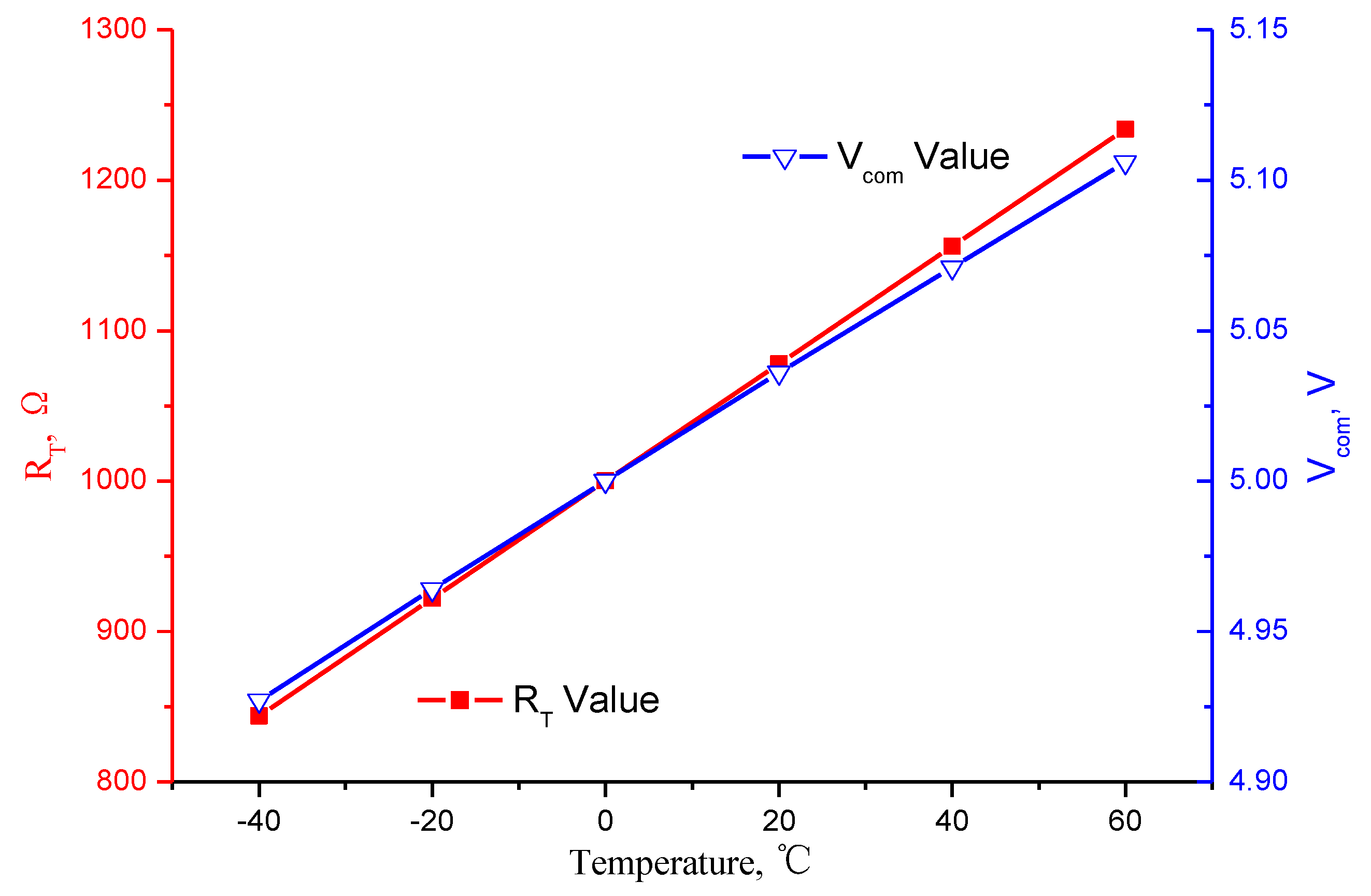
| RT @60 °C | 1234 Ω | Vcom @60 °C | 5.106 V |
| RT @40 °C | 1156 Ω | Vcom @40 °C | 5.071 V |
| RT @20 °C | 1078 Ω | Vcom @20 °C | 5.036 V |
| RT @0 °C | 1000 Ω | Vcom @0 °C | 5.000 V |
| RT @−20 °C | 922 Ω | Vcom @−20 °C | 4.964 V |
| RT @−40 °C | 844 Ω | Vcom @−40 °C | 4.927 V |
| Vf | 10 V | R1 | 4400 Ω |
| - | - | R2 | 5400 Ω |
| Temperature °C | Bias Value (Vbin) °/s | Temperature Coefficient °/(s·°C) | ||
|---|---|---|---|---|
| Test 1 | Test 2 | Test 3 | ||
| 60 | 101.73 | 101.67 | 101.80 | * |
| 40 | 102.31 | 102.30 | 102.34 | |
| 20 | 102.69 | 102.71 | 102.76 | |
| 0 | 103.50 | 103.43 | 103.54 | |
| −20 | 104.49 | 104.37 | 104.43 | |
| −40 | 105.54 | 105.74 | 105.76 | |
| Parameter | Value | Parameter | Value |
|---|---|---|---|
| RTT @60 °C | 1234 Ω | Vout @60 °C | 194.739 mV |
| RTT @40 °C | 1156 Ω | Vout @40 °C | 196.115 mV |
| RTT @20 °C | 1078 Ω | Vout @20 °C | 198.555 mV |
| RTT @0 °C | 1000 Ω | Vout @0 °C | 199.061 mV |
| RTT @−20 °C | 922 Ω | Vout @−20 °C | 197.633 mV |
| RTT @−40 °C | 844 Ω | Vout @−40 °C | 194.272 mV |
| VEE | −1 V | R7 | 10,000 Ω |
| R3 | 12,000 Ω | R8 | 10,000 Ω |
| R6 | 10,000 Ω | - | - |
| Temperature °C | Scale Factor Value mV/(°/s) | Bias Value °/s | ||||||||
|---|---|---|---|---|---|---|---|---|---|---|
| Before Compensation | After Compensation | Before Compensation | After Compensation | |||||||
| Test 1 | Test 2 | Test 3 | Average | Test 1 | Test 2 | Test 3 | Average | |||
| 60 | 7.1185 | 8.7110 | 8.7203 | 8.7300 | 8.7204 | 101.73 | 22.31 | 22.32 | 22.32 | 22.31 |
| 40 | 7.1731 | 8.8202 | 8.8220 | 8.8111 | 8.8178 | 102.32 | 22.26 | 22.28 | 22.28 | 22.27 |
| 20 | 7.1995 | 8.8160 | 8.8010 | 8.8302 | 8.8157 | 102.72 | 22.49 | 22.49 | 22.49 | 22.49 |
| 0 | 7.2417 | 8.7504 | 8.7903 | 8.7730 | 8.7712 | 103.49 | 22.69 | 22.70 | 22.71 | 22.70 |
| −20 | 7.3156 | 8.7231 | 8.7208 | 8.7213 | 8.7217 | 104.43 | 22.66 | 22.69 | 22.70 | 22.68 |
| −40 | 7.3805 | 8.6911 | 8.6811 | 8.6705 | 8.6809 | 105.68 | 22.41 | 22.43 | 22.44 | 22.42 |
| Variation | 3.680% | 1.485% | 1.623% | 1.842% | 1.577% | 3.880% | 1.914% | 1.868% | 1.912% | 1.913% |
| Bias Stability (°/h) | 29.52 | 16.05 | 15.59 | 16.21 | 15.95 | |||||
| Angular Rate Walking (°/h/√Hz) | 1.43 | 1.19 | 1.24 | 1.18 | 1.20 | |||||
© 2019 by the authors. Licensee MDPI, Basel, Switzerland. This article is an open access article distributed under the terms and conditions of the Creative Commons Attribution (CC BY) license (http://creativecommons.org/licenses/by/4.0/).
Share and Cite
Cui, M.; Huang, Y.; Wang, W.; Cao, H. MEMS Gyroscope Temperature Compensation Based on Drive Mode Vibration Characteristic Control. Micromachines 2019, 10, 248. https://doi.org/10.3390/mi10040248
Cui M, Huang Y, Wang W, Cao H. MEMS Gyroscope Temperature Compensation Based on Drive Mode Vibration Characteristic Control. Micromachines. 2019; 10(4):248. https://doi.org/10.3390/mi10040248
Chicago/Turabian StyleCui, Min, Yong Huang, Wei Wang, and Huiliang Cao. 2019. "MEMS Gyroscope Temperature Compensation Based on Drive Mode Vibration Characteristic Control" Micromachines 10, no. 4: 248. https://doi.org/10.3390/mi10040248