1. Introduction
Hollow-core (HC) fibers are optical fibers that can confine the main part of the electric field within a hollow core, along which gases or liquids can flow. Their hollow-core microstructure makes these fibers promising tools for optofluidic applications, for example, as gas sensors [
1,
2]. Meanwhile, the gas-filled HC fiber can be used as a nonlinear medium for supercontinuum [
3,
4,
5] or high-order harmonic generation [
6]. The simplest HC fiber is a capillary; however, its high confinement loss is an inherent problem [
7,
8,
9]. Compared with capillaries, the loss of microstructure HC fibers is much lower. Generally, there are two families of microstructure HC fibers: photonic bandgap fibers (HC-PBGFs) and hollow-core antiresonant fibers (HC-ARFs).
An HC-PBGF has an air core in the center with a periodic structure cladding. The light propagating in the core is confined by the photonic bandgap of the periodic cladding structure. As reported in [
10], the minimum confinement loss of HC-PBGFs can be as low as 1.2 dB/km. However, the bandwidth of HC-PBGFs is only around 10–30% of the central wavelength [
11].
The confinement mechanism of HC-ARFs is different. A series of thin glass walls that function like Fabry–Perot resonators surround the air core in an HC-ARF. This mechanism provides a broad bandwidth for guiding light. In 2017, Wang et al. proposed a clear physical insight into the optical guidance mechanism in HC-ARFs based on a multi-layered model [
12]. In the last few years, several types of HC-ARFs have been studied. The first type is Kagome fibers, which consist of multiple layers of thin glass walls and air holes [
3]. Kagome fibers have a wide bandwidth that can reach several hundred nanometers and have attracted significant interest. It has been shown that Kagome fibers confine the light mainly by the first glass layer around the air core [
13,
14], which motivates the following intensive studies on the negative curvature hollow-core fibers (NC-HCFs) [
15,
16,
17,
18,
19]. The microstructure of NC-HCFs, which typically have one or two thin glass tube claddings, is simpler than that of Kagome fibers. NC-HCFs have been studied widely, and various novel structures have been proposed [
11,
20,
21,
22,
23,
24,
25,
26,
27,
28,
29]. Because of the unique confinement mechanism of NC-HCFs, they can be designed into a slotted structure [
18,
28] to allows gases to flow into the hollow-core.
A general problem with NC-HCFs is that most of the time they support not only the fundamental mode but also a family of higher-order modes (HOMs). However, single-mode guidance is required in many applications. For application in gas sensors, HOMs can give rise to modal interference effects that produce complex patterns of oscillations in the transmitted spectrum [
1]. Improving the single-mode guidance performance of NC-HCFs is necessary before they can be employed in optofluidic applications. In 2016, Uebel et al. proposed a robust broadband single-mode NC-HCF [
15]. The ratio between the diameters of the core and the cladding tubes in their fiber is 0.68. In this way, the LP
11 modes in the core are coupled with the cladding modes and form high-loss supermodes, which results in high confinement loss of the LP
11 modes. Broadband phase matching between the LP
11 and cladding modes provides robust single-mode guidance at all wavelengths within the LP
01 transmission window. To date, only the phase matching for one single HOM has been investigated, but several HOMs may be stimulated simultaneously in a large-core fiber [
30].
Nested antiresonant fibers (NANFs) are NC-HCFs with nested and non-touching antiresonant tube elements arranged around a central core. The confinement loss of the LP
01 modes can be further reduced owing to the double antiresonant layer. Unfortunately, the losses of HOMs in an NANF will be reduced too. In 2018, L. Provino studied the single-mode guidance performance of NANFs [
29]. L. Provino improved the single-mode guidance performance of NANFs by realizing the high-loss supermode of the LP
11 mode. However, the complex cladding tubes of the NANFs lead to different phase-matching conditions worthy of further investigation.
In this paper, we study the single-mode guidance performance of several types of NC-HCFs based on finite element simulations (COMSOL Multiphysics, COMSOL, Stockholm, Sweden). Not only the LP
11 modes but also the LP
21 modes are considered in the suppression of HOMs. To increase the loss of these HOMs, the parameters of the fiber structure are designed to achieve strong coupling between these core modes and cladding modes. The supermodes of the HOMs and cladding modes are high-loss modes; thus, the HOMs are effectively suppressed. The article is structured as follows.
Section 2 elucidates the design principles of single tube layer cladding NC-HCFs with high single-mode guidance performance. Then, we propose a novel NC-HCF with hybrid cladding tubes to improve the single-mode guidance performance. In this kind of fiber, high-loss supermodes of both the LP
11 and the LP
21 modes are realized simultaneously.
Section 3 summarizes the single-mode guidance performance of NANFs. We present the phase-matching condition of NANFs and an LP
11 mode-suppressed NANF structure. A novel nested antiresonant structure with hybrid extended cladding tubes is described in
Section 4. This NANF combines the merits of the NC-HCF with hybrid cladding tubes described in
Section 2 with those of the LP
11 mode-suppressed NANF described in
Section 3. It shows excellent single-mode guidance performance. All of the higher-order mode extinction ratios (HOMERs) calculated at 1040 nm are greater than 10
5. Broadband phase matching for high-loss supermodes is realized. Conclusions are drawn in
Section 5.
2. Single-Mode Guidance Performance of Single Tube Layer Cladding NC-HCFs
In this paper, the fiber material was assumed to be silica. The cladding tube thickness
t = 0.248 μm, which is the first antiresonant thickness for a 1040 nm light wave according to the equation [
19]:
where λ is the wavelength and
nsilica and
nair are the refractive indices of silica and air, respectively. The core diameter
Dcore = 20 × 1040 nm. To accurately calculate the confinement loss, a perfectly matched layer was utilized in the outmost boundary of the geometries. A Sellmeier equation was used to describe the dispersion for silica [
31]. The material loss was neglected, since the material absorption is quite low in this wavelength range [
32]. The refractive index of air was chosen to be 1. The wavelength in this simulation was 1040 nm if not specified otherwise.
Firstly, we study the classical six-tube NC-HCF, whose geometry is shown in
Figure 1a [
15]. All cladding tubes surrounding the core have an equal diameter
Dtube.
Figure 1b shows the simulated loss curves of the fundamental LP
01 (HE
11) modes and six HOMs (TE
01, HE
21, TM
01, EH
11, HE
31, and HE
12) as a function of
Dtube/
Dcore. The loss of the LP
11 group of modes (TE
01, HE
21, and TM
01) has a peak at
Dtube/
Dcore = 0.68, which is the same as in [
15]. When
Dtube/
Dcore = 0.68, the effective refractive index (
neff) of the LP
11 modes in the core is equal to that of the fundamental mode in the cladding tube, and, as a result, a high-loss supermode is formed. This could be explained by the equation [
15]:
where the fitting parameters are
for the core and
for the cladding tube, and
ulm is the m-th zero of the Bessel function
. The cladding tube diameter has little influence on the loss of the LP
01 modes because the effective index of the fundamental core mode in the NC-HCF core is larger than that of the fundamental mode in the annular cladding tube when they have the same diameter [
19]. Meanwhile, the effective index increases with the diameter of an annular tube but the cladding tubes always have a smaller diameter than the core. As a result, phase matching between the LP
01 and cladding tube modes occurs only when
Dtube is larger than
Dcore. However, it cannot happen in an NC-HCF with six cladding tubes. The mode patterns of LP
01 and LP
11 modes when
Dtube/
Dcore = 0.68 are shown in
Figure 1c, where a supermode is clearly observed for the LP
11 modes. LP
21 (EH
11 and HE
31) and LP
02 (HE
12) modes both have two high-loss peaks. The first peak, at
Dtube/
Dcore = 0.52 for the LP
21 modes and
Dtube/
Dcore = 0.49 for the LP
02 modes, is a result of coupling between the respective HOM in the core and the fundamental mode of the cladding tubes. The second peak, which appears at
Dtube/
Dcore = 0.81 for the LP
21 modes and
Dtube/
Dcore = 0.77 for the LP
02 modes, results from the coupling with the LP
11 modes of the cladding tubes. The supermodes corresponding to the loss peaks in
Figure 1b are also shown in
Figure 1c.
The first HOM that could be excited in an NC-HCF is the LP
11 modes, which means that applying cladding tubes with a diameter
Dtube = 0.68
Dcore in an NC-HCF could improve the single-mode guidance performance of the fiber. Although an NC-HCF with
Dtube/
Dcore = 0.68 can suppress the LP
11 modes of the fiber, the LP
21 modes are not strongly suppressed. The loss of the EH
11 mode is only 17.1 dB/m when
Dtube = 0.68
Dcore. To effectively increase the loss of the LP
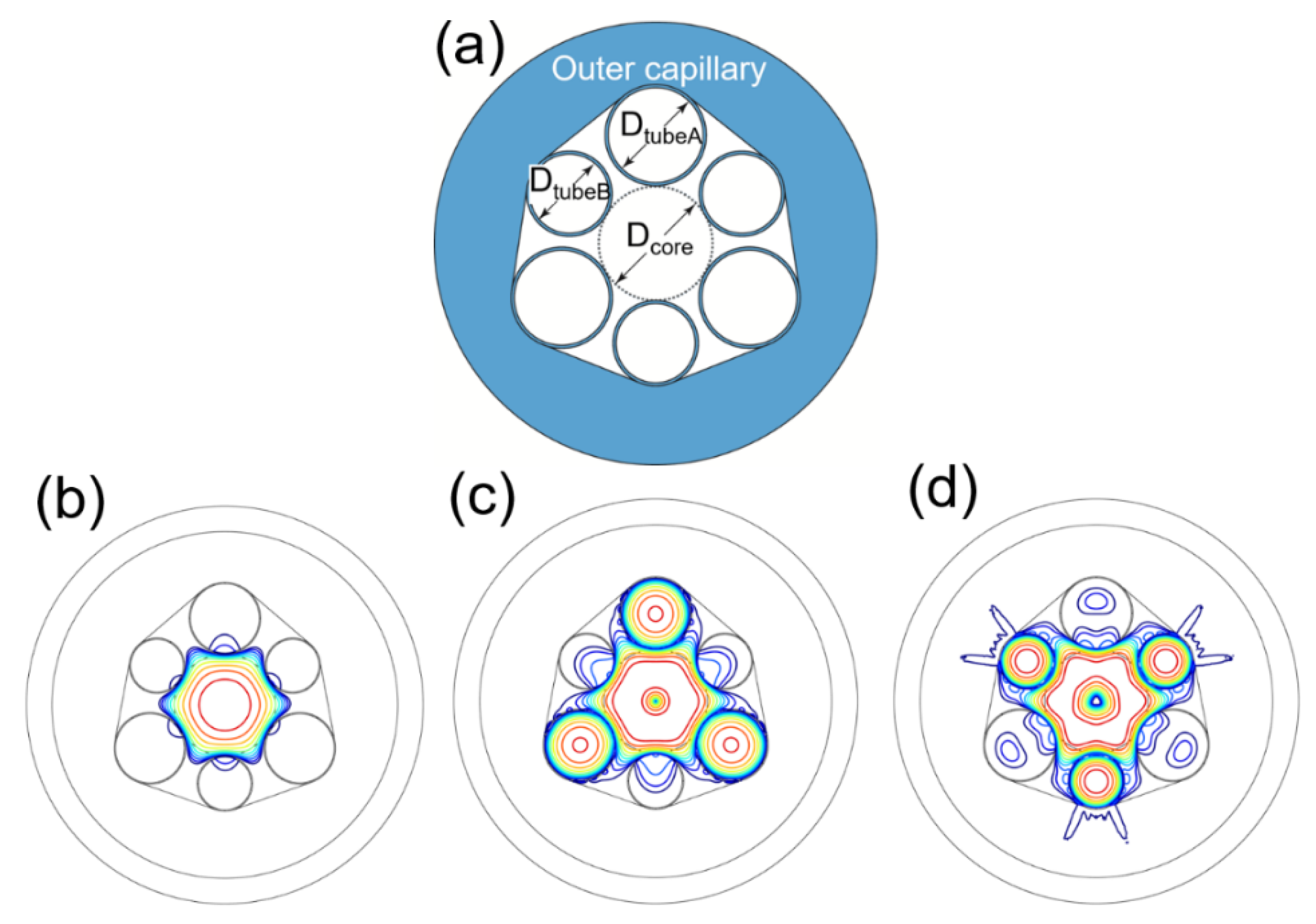
21 modes, we propose a novel NC-HCF with hybrid cladding tubes, as shown in
Figure 2a. Three of the cladding tubes have diameter
DtubeA = 0.68
Dcore, and the others have diameter
DtubeB = 0.52
Dcore. Different cladding tubes are placed alternately around the fiber core. The inner boundary of the outer capillary is a polygon with rounded corners that closely fits the adjacent cladding tubes. From the analysis above, it is not surprising to see that both the LP
11 and LP
21 modes form high-loss supermodes, as verified in
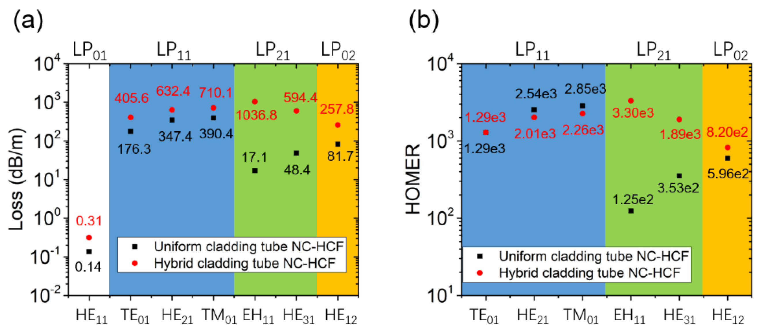
Figure 2b–d. The higher-order mode extinction ratio (HOMER) is commonly used to quantitatively describe the single-mode performance [
23]. The HOMER is defined as the ratio of the loss of the higher-order core modes to that of the fundamental mode. For comparison, the loss and HOMER of the hybrid NC-HCF and those of the corresponding NC-HCF with uniform cladding tubes (
Dtube = 0.68
Dcore) are shown in
Figure 3.
The losses and effective refractive indexes of the fiber for the two polarizations were calculated. There is no obvious difference in the fiber mode indices in the two polarizations. In both the vertical and horizontal polarizations in
Figure 2a, the loss of the LP
01 mode is 0.31 dB/m and the effective refractive index is 0.999374, which means that there is no birefringence in the hybrid NC-HCF. The outer capillary of the hybrid cladding tube NC-HCF leads to a higher loss for all the modes. Nevertheless, both the LP
11 and LP
21 modes can be coupled to the cladding modes effectively and form high-loss supermodes, which allow their HOMERs to reach a level of 1000. The HOMERs of the LP
11 modes in the hybrid NC-HCF are close to those of the uniform structure. However, the HOMERs of the LP
21 modes in the hybrid NC-HCF are notably larger than those of the uniform structure because phase matching for the LP
21 modes is also achieved in the hybrid NC-HCF. Neither of the two fibers can achieve efficient phase matching for the LP
02 mode, so they have close HOMER values. As a result of applying the hybrid cladding tubes, the fiber can suppress the LP
11 and LP
21 modes simultaneously.
3. Single-Mode Guidance Performance of NANFs
Compared with NC-HCFs, which have only one antiresonant layer, NANFs could reduce not only the confinement loss of the LP
01 fundamental modes but also that of the HOMs. The geometry of a typical NANF structure, consisting of six nested tubes, is shown in
Figure 4a. Compared with a single antiresonant layer NC-HCF, the phase-matching scenario for high-loss supermodes in an NANF is more complicated. Two cladding modes (CM1 and CM2) are typically involved in the phase matching. CM1 is located in the middle of the first and second cladding tubes, as shown in
Figure 4b. CM2 is located inside the second cladding tube, as shown in
Figure 4c.
To explore the phase matching between the LP
11 and CM1 modes, we keep the first cladding tube diameter at
Dtube1 = 0.80
Dcore and change the second cladding tube diameter [
29]. The loss of the LP
11 modes as a function of
Dtube2/
Dcore is shown in
Figure 5a and reaches a maximum at
Dtube2/
Dcore = 0.23. However, the loss of the LP
01 modes increases as the value of
Dtube2/
Dcore is reduced and the second cladding tube prevents the LP
11 supermode from reaching a high loss, as can be seen from the mode pattern in
Figure 5c. When
Dtube1 = 0.80
Dcore and
Dtube2 = 0.23
Dcore, the loss of the LP
01 modes is 1.47 × 10
−3 dB/m, which is quite high for NANFs, while the loss of the LP
11 modes is no more than 5 dB/m.
It is more difficult to realize phase matching between the LP
11 and CM2 modes. Because CM2 is a circular tube mode, the phase-matching condition for a high-loss supermode should be close to
Dtube2 = 0.68
Dcore. We therefore sweep
Dtube1 for
Dtube2/
Dcore = 0.66, 0.67, 0.68, 0.69, and 0.70. The results are shown in
Figure 5b. The maximum loss of the LP
11 mode is 26.9 dB/m and appears at
Dtube1 = 0.80
Dcore and
Dtube2 = 0.68
Dcore, simply the smallest
Dtube1 with
Dtube2 = 0.68
Dcore in our sweep range. The mode pattern of this supermode is displayed in
Figure 5d. The LP
01 mode loss of this structure is as high as 5.85 × 10
−3 dB/m. Whether the LP
11 modes are coupled with CM1 or CM2, their loss cannot be raised to more than 100 dB/m, which can be realized in NC-HCFs with one antiresonant layer. At the same time, the loss of the LP
01 mode is too high. It is not effective to improve the single-mode guidance performance by coupling the HOM only with one single cladding mode in an NANF if a low loss of the LP
01 mode is desired.
To further increase the loss of the LP
11 modes in the NANFs and meanwhile maintain a low loss of the LP
01 modes, we turn to a structure with five nested tubes, as illustrated in
Figure 6a. In this way, the area of the cladding modes becomes larger, and, as a result, the HOMs can be coupled with the cladding modes more strongly. A structure with fewer nested tubes could have a larger
Dtube1, which makes it possible to realize phase matching between the LP
11, CM1, and CM2 modes. The losses of the LP
11 modes as a function of
Dtube1/
Dcore for
Dtube2/
Dcore = 0.66, 0.67, 0.68, 0.69, and 0.70 are shown in
Figure 6b. An interesting result is that for each
Dtube2, the maximum loss value appears when
Dtube1/
Dtube2 is close to 1.75. This result indicates that
Dtube1/
Dtube2 = 1.75 fulfils the phase-matching condition between CM1 and CM2. The mode loss is higher when
Dtube2 = 0.69
Dcore. The maximum loss of the LP
11 mode is 313.96 dB/m when
Dtube1 = 1.21
Dcore and
Dtube2 = 0.69
Dcore, and the mode pattern is shown in
Figure 6d. The loss of the LP
01 modes is only 3.64 × 10
−4 dB/m. Thus, the cascaded coupling between the LP
11, CM1, and CM2 modes increases the LP
11 mode loss significantly. However, the LP
21 and LP
02 modes have different phase-matching conditions. We then keep
Dtube2 = 0.69
Dcore and sweep
Dtube1 to study the loss of the other modes. As displayed in
Figure 6c, similar to the case in a single tube layer cladding NC-HCF, both LP
21 and LP
02 modes have two high-loss peaks that correspond to different HOMs of CM1. The high-loss peaks of the LP
21 modes appear at
Dtube1 = 1.17
Dcore and
Dtube1 = 1.27
Dcore, and the high-loss peaks of the LP
02 modes appear at
Dtube1 = 1.13
Dcore and
Dtube1 = 1.23
Dcore.
4. NANFs with Extended Cladding Tubes
As illuminated in
Section 3, the cascaded coupling between the HOMs in the fiber core and the cladding modes can raise the loss of the HOMs by increasing the area of the cladding modes. It is impossible to realize the cascaded coupling in NANFs with six nested circular cladding tubes. It is also impossible to alternately place the hybrid claddings tubes in an NANF with five nested tubes. To increase the area of CM1 in an NANF with six nested tubes, we propose a novel NANF with extended cladding tubes with the geometry shown in
Figure 7a. The first cladding tube is extended with a length of
l. To simplify the design process, we keep
Dtube1 = 0.80
Dcore.
The loss of the LP
11 modes in the NANF with extended cladding tubes is investigated as a function of
l when
Dtube2/
Dcore = 0.66, 0.67, 0.68, 0.69, and 0.70, as shown in
Figure 7b. The maximum loss value is 343.7 dB/m when
l = 9.4 × 1040 nm and
Dtube2/
Dcore = 0.69. On the other hand, the LP
21 mode loss as a function of
l when
Dtube2/
Dcore = 0.50, 0.51, 0.52, 0.53, and 0.54 is shown in
Figure 7c. The maximum loss value is 1270.3 dB/m when
l = 9.3 × 1040 nm and
Dtube2/
Dcore = 0.51. Interestingly, the loss peaks of these two HOMs are close to each other. The second-largest value of the LP
21 mode loss is 1153.3 dB/m when
l = 9.4 × 1040 nm and
Dtube2/
Dcore = 0.51. As a result, it is very easy to apply a hybrid cladding tube structure in NANFs with extended cladding tubes. The geometry of the NANF with hybrid extended cladding tubes is shown in
Figure 8a. All of the first cladding tubes have an extended length
l = 9.4 × 1040 nm. Three of the second cladding tubes have an inner diameter of
Dtube2A = 0.69
Dcore and the others an inner diameter of
Dtube2B = 0.51
Dcore. The nested cladding tubes are alternately arranged. The mode patterns of the LP
01, LP
11, and LP
21 modes are shown in
Figure 8b–d, respectively. As can be clearly observed, high-loss supermodes are realized for both the LP
11 and LP
21 modes.
As for the hybrid NC-HCF, the losses and effective refractive indexes of the fiber in the two polarizations were calculated. In the vertical polarization in
Figure 8a, the LP
01 mode loss is 3.90 × 10
−4 dB/m and is 4.05 × 10
−4 dB/m in the horizontal polarization. In both polarizations, the effective refractive index is 0.999363, which means that there is no birefringence in the NANF with hybrid extended cladding tubes. Then, we made a comparison between the two HOM-suppressed NANFs in
Figure 9. One structure considered is an NANF with five nested tubes of parameters
Dtube1 = 1.21
Dcore and
Dtube2 = 0.69
Dcore, the circular tube NANF with the best single-mode guidance performance in
Section 3. The other structure is an NANF with hybrid extended cladding tubes proposed in this Section. The LP
01 mode loss of the NANF with five nested tubes is 3.64 × 10
−4 dB/m. The NANF with hybrid extended cladding tubes has a slightly higher LP
01 mode loss of 3.90 × 10
−4 dB/m. The NANF with five nested tubes has a higher LP
11 mode loss. Although the NANF with five nested tubes has a HOMER of the level of 10
3 for the LP
21 modes, the NANF with hybrid extended cladding tubes can achieve a level of 10
5 or even 10
6 for the LP
21 modes because of its extremely high LP
21 mode loss. A HOMER level of 10
5 for the LP
20 modes is also obtained for the NANF with hybrid extended cladding tubes. Thus, the NANF with hybrid extended cladding tubes overall permits a more effective single-mode guidance performance.
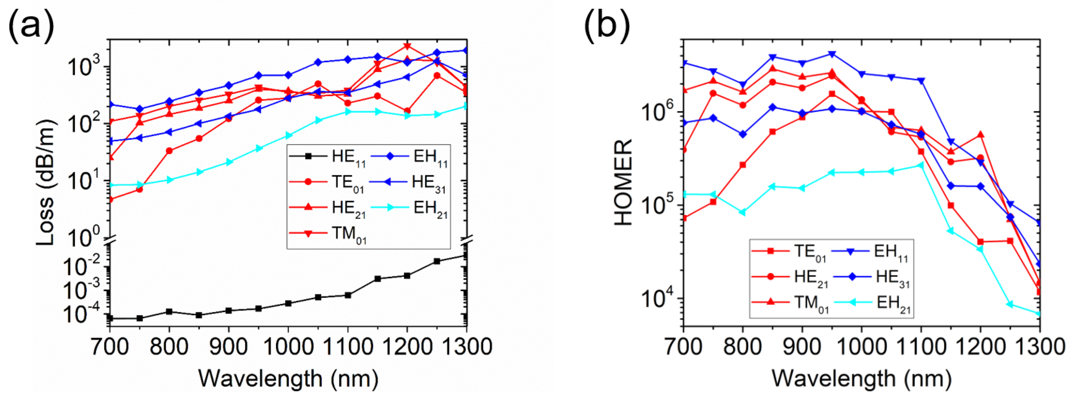
In the end, we verified the broadband guidance of the NANF with hybrid extended cladding tubes. The loss and the HOMER as a function of wavelength in the range 700–1300 nm are displayed in
Figure 10. The losses increase at long wavelengths because the ratio between the core diameter and wavelength becomes lower. A relatively large core could reduce the loss. Similar to the nested elliptical cladding tube NANF in [
23], the loss of the fundamental mode of the NANF with hybrid extended cladding tubes rises quickly at long wavelengths. As a result, the HOMERs are reduced at long wavelengths. Phase matching for the LP
11 and LP
21 modes are achieved in the wavelength range, so the HOMERs are higher than 10
4 at most wavelengths. At shorter wavelengths, the HOMERs are typically above 10
5.


