Article

An Innovative Synthetic Aperture Radar Design Method for Lunar Water Ice Exploration

1
Aerospace Information Research Institute, Chinese Academy of Sciences, Beijing 100190, China
2
School of Electronic, Electrical and Communication Engineering, University of Chinese Academy of Sciences, Beijing 100039, China
3
National Key Laboratory of Microwave Imaging Technology, Beijing 100190, China
*
Author to whom correspondence should be addressed.
Remote Sens. 2022, 14(9), 2148; https://doi.org/10.3390/rs14092148
Submission received: 6 March 2022 / Revised: 27 April 2022 / Accepted: 27 April 2022 / Published: 30 April 2022
(This article belongs to the Special Issue Radar for Planetary Exploration)

Abstract

:
Owing to the Moon’s rough surface, there is a growing controversy over the conclusion that water ice exists in the lunar permanently shadowed regions (PSRs) with a high circular polarization ratio (CPR). To further detect water ice on the Moon, an innovative design method for spaceborne synthetic aperture radar (SAR) system is proposed, to obtain radar data that can be used to distinguish water ice from lunar regolith with a small difference in the dielectric constants. According to Campbell’s dielectric constant model and the requirement that SAR radiometric resolution is smaller than the contrast of targets in images, a newly defined SAR system function involved in the method is presented to evaluate the influence of some system parameters on the water ice detection capability of SAR. In addition, several simulation experiments are performed, and the results demonstrate that the presented SAR design method may be helpful for lunar water ice exploration.

1. Introduction

Permanently shadowed regions (PSRs) on the Moon refer to the regions that do not see the Sun for geologically long periods [1]. PSRs have an extremely low temperature (<120 K), and can function as a trap for volatile substances [1]. Therefore, PSRs are considered the primary containers for storing water ice on the Moon [1,2].
Water is very important for building bases on the Moon to explore deep space, and some studies regarding lunar water ice exploration have been conducted. In 1998, Feldman et al. [3,4] analyzed the neutron data collected by the Lunar Prospector Neutron Spectrometer (LP-NS) for the first five months and found the count-rate of epithermal neutrons decreases at lunar poles, which provided strong evidence for the hydrogen abundance in and around the lunar PSRs. Then, the LCROSS mission [5,6,7] in 2009 first detected the potential abundance of water and other volatiles (∼5 wt. % water) from the ejecta plume of the impact. Another powerful and widely used sensor is radar, which can detect water ice beneath the lunar regolith and maps the distribution of water ice in a large region. In 1994, the bistatic radar experiment of the Clementine spacecraft detected that the increasing circular polarization ratio (CPR) was in the PSRs of the lunar south pole [8], but not in sunlit areas, which was interpreted as that the high CPR values were caused by the presence of water ice [9]. However, Stacy et al. in 1997 analyzed the experimental data from the high-resolution Earth-based Arecibo radar and revealed several radar enhancements associated with impact features, many of which were in sunlit areas [10,11]. These results implied that there was less evidence for large expanses of water ice at the Moon’s south pole [11]. In 2006, Campbell et al. [12] used the Arecibo radio telescope to observe the Shackleton crater at the lunar south pole, and the results indicated that there were no large expanses of water ice near the Shackleton or elsewhere in the Earth-visible vicinity of the pole. Furthermore, Spudis et al. analyzed the radar data from Chandrayaan-1 and so on and concluded that water ice may be responsible for the high CPR in lunar anomalous craters [13,14]. In 2013, based on a two-component mixed radar scattering model and additional statistical study, Fa and Cai proposed that the high CPR in anomalous polar craters might be caused by the roughness of the lunar surface [15]. After that, Patterson et al. [16] processed the bistatic radar data of Arecibo observing the Moon in 2016 and concluded that there may be water ice beneath the lunar surface. Thus, identifying the water ice and mapping its distribution using radar techniques is still controversial.
At present, the lunar PSRs [13,14,17,18] are primarily irradiated by the circularly polarized waves transmitted by synthetic aperture radar (SAR), and their co- and de-polarized echoes are analyzed to detect the large expanses of water ice that may be carried by the falling comets and asteroids [19]. However, the contamination of the rough lunar surface leads to an increase in the energy of co-polarized echo signals, which makes the discovery of water ice in the Moon’s PSRs by high CPR controversial [20,21,22,23,24]. As such, this paper proposes an innovative SAR design method to evaluate the influence of the radar incidence angle, the number of multi-looks, quantization precision of the receiver, average transmitting power, and so on, on the lunar water ice detection capability of SAR. Based on this method, the designed SAR system can obtain radar data to distinguish the dielectric constants of lunar regolith and water ice, and the method may be applied in lunar water ice exploration.
The content of the paper is arranged as follows. Section 2 describes the challenges of lunar water ice exploration, Campbell’s dielectric constant model, and radar radiometric resolution. Section 3 presents a SAR system function and proposes an innovative SAR design method for lunar water ice exploration. Section 4 carries out several simulation experiments to evaluate the influence of radar parameters on the water ice detection capability of SAR. Section 5 discusses the lunar water ice exploration in the future, and a conclusion is given in Section 6.

2. Preliminaries

2.1. Pitfalls

The geometry and dielectric constant are two major factors in the detection of lunar water ice by SAR. Because the existing form and content of lunar water have not been determined, and the satellite orbit measurement accuracy is not high enough [25], it is extremely difficult for the radar system to accurately measure the geometry of lunar water ice using interferometry [26]. Thus, for radar systems, whether there is water ice on the Moon can only be determined by analyzing the dielectric constants derived from the radar backscattering coefficients.
For the sake of analysis, it can be assumed that the top layer of the Moon is primarily composed of a mixture of lunar regolith and water ice, and its dielectric constant can be expressed as
ε f · ε i c e + ( 1 f ) · ε r e g ,
where ε i c e and ε r e g represent the dielectric constants of water ice and lunar regolith, respectively, of which the specific parameters are shown in Table 1, f represents the scale factor of water ice, and f [ 0 , 1 ] [15].
According to (1) and Table 1, the variation in the dielectric constants of mixtures with f is obtained. It can be derived that the maximum and minimum dielectric constants of the mixtures of lunar regolith and water ice are ε m a x = 3.15 and ε m i n = 2.7 , respectively, and the small difference between the two components in the dielectric constants makes it difficult to distinguish them. Therefore, it is extremely difficult to determine the existence of water ice and to estimate the content of that on the Moon based on dielectric constants. To realize the accurate detection of lunar water ice, the radar systems that can obtain the echo data to distinguish the water ice from lunar regolith must be specifically designed. As such, this paper based on Campbell’s dielectric constant model and the SAR radiometric resolution described below proposes an innovative SAR design method for the detection of lunar water ice (see Figure 1). The details are described in Section 3.

2.2. Campbell Model

B.A. Campbell et al. studied the radar penetration in the Mars analog environments and proposed a normalized ratio of the horizontal and vertical polarization backscattering coefficients to describe the dielectric inversion model for rock-poor mantling dust in 2002 [27]. This model has been widely used in lunar water ice exploration, and it is described as
ε = ( sin ϕ / sin [ cos 1 ( σ LH 0 σ LV 0 ) 0.25 ϕ ] ) 2 ,
where ϕ is the incidence angle, ε is the estimated dielectric constant value, L denotes the transmitted left-handed circular polarization signal, and σ LH 0 and σ LV 0 are the backscattering coefficients of the circular polarization echoes that are received by the horizontal (H) and vertical (V) polarization antennas, respectively [27,28,29].

2.3. Radiometric Resolution

Radiometric resolution is the minimum change in the input that can be detected by the output, and it is determined by the standard deviation of the system input noise temperature [30]. In the aperture synthesis systems [31], the imaging mode and hardware structure will affect the radiometric resolution, i.e., the minimum difference (minimum contrast) between targets in radar images [32,33]. To date, there are some definitions of SAR radiometric resolution, and the most commonly used one is expressed as
r = 10 · log 10 1 + 1 L l o o k ( 1 + 1 SNR ) ,
where L l o o k denotes the number of multi-looks, and SNR is the signal-to-noise ratio of the radar system [32,33].
SNR is inversely proportional to the noise equivalent backscattering coefficient ( N E σ 0 ) of the system, which can be described as Equation (4) [34].
N E σ 0 ( ϕ ) = σ 0 ( ϕ ) SNR ( ϕ ) = 4 · ( 4 π ) 3 · R 3 · V s · sin ϕ · K · T o · B r · F n · L s P a v · G t · G r · λ 3 · C ,
where σ 0 denotes the backscattering coefficient of targets, ϕ is the incidence angle, R is the slant distance, V s is the satellite speed, K = 1.38054 E 23 J/K is the Boltzmann constant, T o is the network temperature, B r is the signal bandwidth, F n is the noise coefficient of receivers, L s is the system loss, P a v is the average transmitting power, G t and G r represent the transmitting and receiving antenna patterns, respectively, λ is the wavelength, and C is the speed of light [34].
To address the challenges of the lunar water ice exploration, this paper based on the Campbell model and SAR radiometric resolution proposes an innovative design method for spaceborne SAR.

3. System Design Method

The goal of the water ice exploration on the Moon mainly involves (1) determining whether there is water ice; (2) estimating the content of water ice. These require SAR to distinguish the pure water ice and lunar regolith and to estimate the content of water ice in their mixtures. They are detailed in the following.

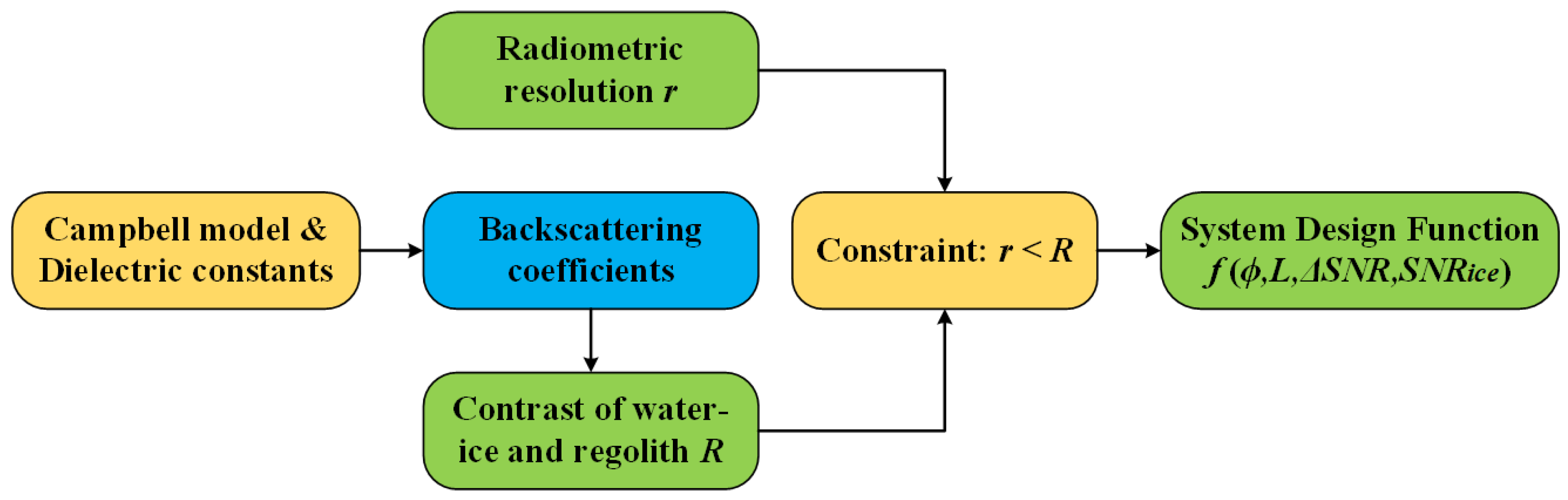
3.1. System Function for Pure Water Ice

It is a well-known method to use the CPR [15] to detect the possible water ice in the PSRs of lunar polar regions. However, the secondary scattering from the rough lunar surface will lead to the increase in CPR, hindering the detection of water ice. To achieve accurate detection, this paper based on (3) and the requirement that SAR radiometric resolution should be less than the contrast of targets in images [33] presents a newly defined system function, of which the main contents are shown in Figure 1.
First, the ratios of the H and V polarization backscattering coefficients of the lunar regolith and water ice are obtained based on (2) and their dielectric constants, and they are respectively expressed as
σ L H r e g 0 σ L V r e g 0 = [ cos ( sin 1 sin ϕ ε r e g + ϕ ) ] 4 ,
σ L H i c e 0 σ L V i c e 0 = [ cos ( sin 1 sin ϕ ε i c e + ϕ ) ] 4 ,
where σ L H r e g 0 , σ L V r e g 0 , σ L H i c e 0 and σ L V i c e 0 separately represent the backscattering coefficients of the echo signals that are received by the H and V antennas after the left-handed circular polarization signals are scattered from the lunar regolith and water ice, and ϕ is the incidence angle [27].
For the spaceborne SAR with the thermal noise power and sensitivity of P n and N E σ 0 respectively, the total energy of the radar echoes scattered from the water ice and lunar regolith, which are received by the H (V) antenna, can be separately described as ([32]):
P i c e = σ L H i c e 0 · P n N E σ 0 + P n ,
P r e g = σ L H r e g 0 · P n N E σ 0 + P n .
Furthermore, the ratios of the echo signals from the lunar regolith and water ice received by the H and V polarization antennas can be expressed as Equations (9) and (10), respectively. They are the contrasts (If the contrast approaches one, two targets cannot be distinguished based on the difference in the echo signal energy, while, conversely, if the contrast tends to zero or infinity, they can be distinguished) of the lunar regolith and water ice [32,33].
R H = P H r e g P H i c e = σ L H r e g 0 · P n N E σ 0 + P n σ L H i c e 0 · P n N E σ 0 + P n = σ L H r e g 0 + N E σ 0 σ L H i c e 0 + N E σ 0
R V = P V r e g P V i c e = σ L V r e g 0 · P n N E σ 0 + P n σ L V i c e 0 · P n N E σ 0 + P n = σ L V r e g 0 + N E σ 0 σ L V i c e 0 + N E σ 0
According to the rule of thumb, the radiometric resolution (r) required by the system design of spaceborne SAR is less than the contrast of targets in radar images, that is, Equation (11) must be satisfied [32], where R i represents the contrast of two targets, i { H , V } .
r R i
Based on Equations (3), (9)–(11), this paper derives the basic constraints required for the system design of spaceborne SAR, and they are described as
1 + 1 L l o o k ( 1 + 1 SNR ) σ L H r e g 0 + N E σ 0 σ L H i c e 0 + N E σ 0 ,
1 + 1 L l o o k ( 1 + 1 SNR ) σ L V r e g 0 + N E σ 0 σ L V i c e 0 + N E σ 0 .
Moreover, the modified constraint of spaceborne SAR can be obtained by transforming (5) and (6) separately and substituting them into (12), and it can be expressed as
1 + 1 L l o o k ( 1 + 1 SNR ) cos ( sin 1 sin ϕ ε r e g + ϕ ) 4 · σ L V r e g 0 + N E σ 0 cos ( sin 1 sin ϕ ε i c e + ϕ ) 4 · σ L V i c e 0 + N E σ 0 .
Comparing the constraints described by (13) and (14), it is obvious that the right part of (13) is greater than that of (14), that is, the constraint of the spaceborne SAR system designed for lunar water ice exploration can be unified into
1 + 1 L l o o k ( 1 + 1 SNR ) cos ( sin 1 sin ϕ ε r e g + ϕ ) 4 · SNR r e g + 1 cos ( sin 1 sin ϕ ε i c e + ϕ ) 4 · SNR i c e + 1 .
For the spaceborne SAR system adopting side-view imaging, the SNR of the echo signals scattered from the lunar regolith is greater than that of the water ice [15,17]. As such, the constraint of system design can be further recast as
1 + 1 L l o o k ( 1 + 1 SNR i c e ) cos ( sin 1 sin ϕ ε r e g + ϕ ) 4 · SNR r e g + 1 cos ( sin 1 sin ϕ ε i c e + ϕ ) 4 · SNR i c e + 1 .
f ( ϕ , L l o o k , SNR r e g , SNR i c e ) = cos ( sin 1 sin ϕ ε r e g + ϕ ) 4 · SNR r e g cos ( sin 1 sin ϕ ε i c e + ϕ ) 4 · SNR i c e 1 L l o o k ( 1 + 1 SNR i c e ) cos ( sin 1 sin ϕ ε i c e + ϕ ) 4 · SNR i c e · 1 L l o o k ( 1 + 1 SNR i c e ) s t . f ( ϕ , L l o o k , SNR r e g , SNR i c e ) 0
f ( ϕ , L l o o k , Δ SNR , SNR i c e ) = cos ( sin 1 sin ϕ ε r e g + ϕ ) 4 · ( SNR i c e + Δ SNR ) cos ( sin 1 sin ϕ ε i c e + ϕ ) 4 · SNR i c e 1 L l o o k ( 1 + 1 SNR i c e ) cos ( sin 1 sin ϕ ε i c e + ϕ ) 4 · SNR i c e · 1 L l o o k ( 1 + 1 SNR i c e ) s t . f ( ϕ , L l o o k , Δ SNR , SNR i c e ) 0
f ( ϕ , L l o o k , Δ SNR , SNR m i x , f ) = cos ( sin 1 sin ϕ ε r e g + ϕ ) 4 · ( SNR m i x + Δ SNR ) cos ( sin 1 sin ϕ ε m i x + ϕ ) 4 · SNR m i x 1 L l o o k ( 1 + 1 SNR m i x ) cos ( sin 1 sin ϕ ε m i x + ϕ ) 4 · SNR m i x · 1 L l o o k ( 1 + 1 SNR m i x ) s t . f ( ϕ , L l o o k , Δ SNR , SNR m i x , f ) 0
By transforming Equation (16), the newly defined system function of the spaceborne SAR that can distinguish the water ice and lunar regolith is described by Equation (17), as shown at the top of this page.
It can be assumed that the SNR of the echo signals scattered from the lunar regolith and water ice satisfies SNR r e g SNR i c e = Δ SNR . Therefore, they can be distinguished only when the minimum interval of the SNR of echo signals measured by the receiver is less than Δ SNR . Furthermore, the final system function related to the incidence angle, the number of multi-looks, the quantization accuracy of receivers, and the SNR of water ice can be expressed by Equation (18), as shown at the top of this page.
The system function described by (18) is an important index for designing the SAR system of lunar water ice exploration. Moreover, the resolution of the dielectric constant obtained from the echoes obtained by the SAR satisfying (18) is less than the minimum difference between the dielectric constants of the lunar regolith and water ice, which guarantees the detection of pure water ice on the Moon.

3.2. System Function for Mixtures

For the purpose of estimating the content of water ice on the Moon, SNR i c e and ε i c e in (18) need to be modified to be SNR m i x and ε m i x . SNR m i x and ε m i x respectively represent the SNR and dielectric constant of the mixture (lunar regolith and water ice). Then, the modified system function is described as Equation (19), where f represents the scale factor of water ice in the mixture, and ε m i x is equal to (1).
According to (19), the influence of the content of water ice in the mixture on the system design of spaceborne SAR can be evaluated, which places higher requirements for the lunar water ice exploration.

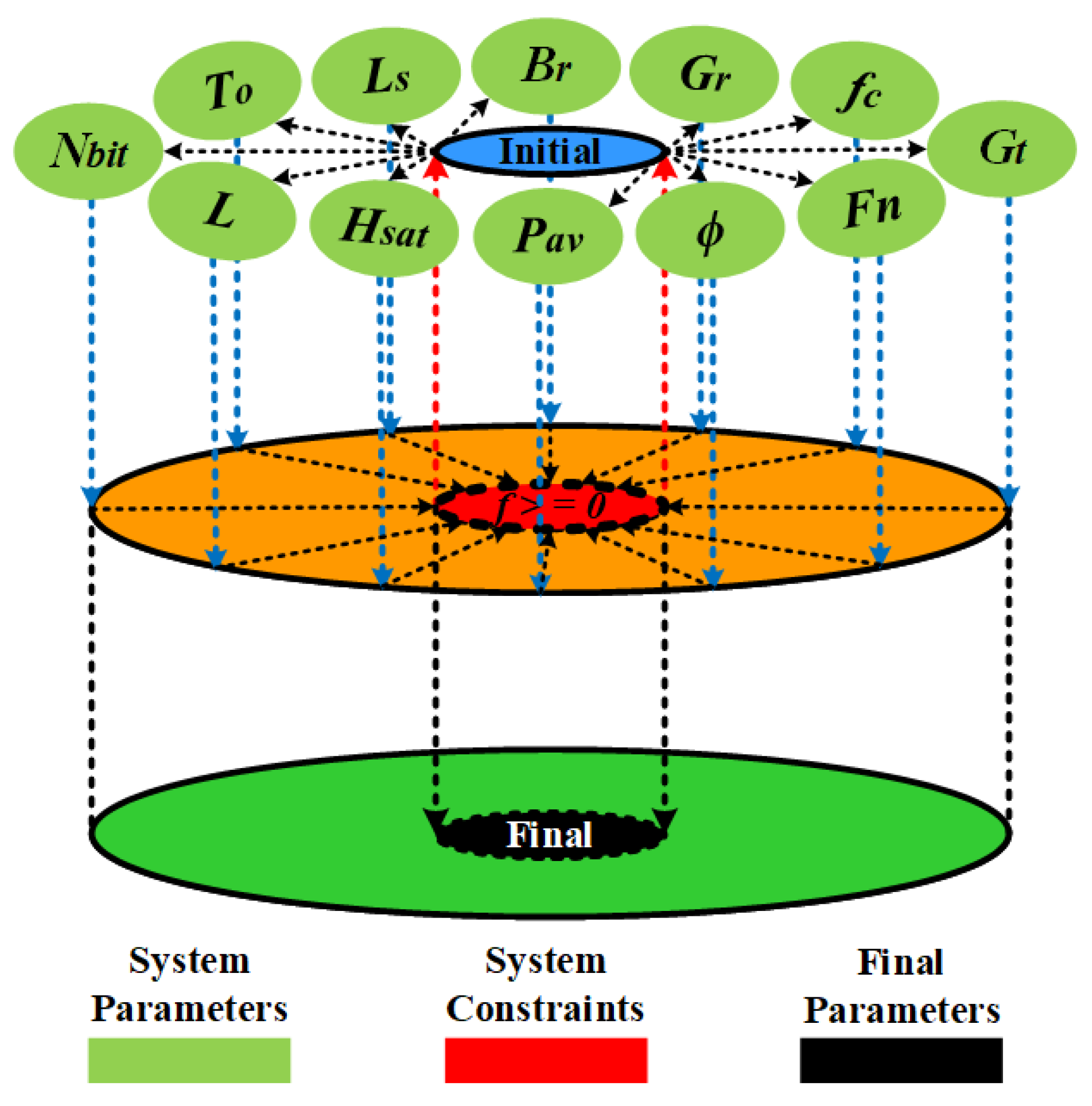
3.3. System Design Method

In this section, the schematic diagram of SAR system design for the lunar water ice exploration is described, as shown in Figure 2.
It can be seen from Figure 2 that the proposed innovative system design method for spaceborne SAR is primarily composed of six steps, as follows:
  • the initial input values described by the blue ellipse are assigned to the SAR system parameters represented by the light green ellipses;
  • based on (18) and (19), the values of the proposed SAR system function can be calculated, which is denoted as the orange circle;
  • it needs to be determined whether these system function values satisfy the constraint expressed in (18) and (19), which is described as the red ellipse;
  • if the constraint is satisfied, the final system parameters of spaceborne SAR are obtained, which are denoted by the black ellipse, and the SAR system design process is terminated;
  • otherwise, the initial parameters are modified and optimized, which are described as the red dashed lines with direction;
  • the first five steps are looped until the constraint in (18) and (19) is satisfied, and the final system parameters of spaceborne SAR are derived.
After performing the six steps, the spaceborne SAR system can be designed and used to distinguish the pure water ice and lunar regolith or to estimate the content of water ice on the Moon.
In short, the newly defined system function is the most basic requirement and provides the theoretical basis for the SAR system to detect the lunar water ice. In addition, several simulation experiments are carried out in the following to further evaluate the significance of the proposed SAR design method for lunar water ice exploration.

4. Experimental Results

In the following, many simulation experiments based on the proposed design method are executed to evaluate the influence of various factors on the water ice detection capability of spaceborne SAR. First, SNR i c e and Δ SNR in (18) can be clarified based on (4), and they are respectively described as
SNR ( ϕ ) = σ 0 ( ϕ ) · P a v · G t · G r · λ 3 · C 4 · ( 4 π ) 3 · R 3 · V s · sin ϕ · K · T o · B r · F n · L s ,
Δ SNR ( ϕ ) = K s c a l e · Δ σ 0 ( ϕ ) = K s c a l e · | σ r e g 0 ( ϕ ) σ i c e 0 ( ϕ ) | ,
where K s c a l e = P a v · G t · G r · λ 3 · C 4 · ( 4 π ) 3 · R 3 · V s · sin ϕ · K · T o · B r · F n · L s [34].
Assuming that the dynamic range of the receiver is denoted as D R r , its sampling accuracy can be expressed as
B D = | σ r e g 0 ( ϕ ) σ i c e 0 ( ϕ ) | D R r .
Furthermore, the quantization bit rate of the corresponding receiver can be described as
N b i t = C e i l ( l o g 2 B D ) ,
where C e i l ( ) denotes the smallest integer greater than [34].
Based on (18)–(22), the constraint of the improved spaceborne SAR system function for the lunar water ice exploration can be obtained, and it is expressed as
f ( ϕ , L l o o k , σ 0 ( ϕ ) , P a v , G t , G r , λ , H s a t , V s , T o , B r , F n , L s ) 0 ,
where H s a t represents the satellite height [34].
According to (24), it can be seen that the factors related to the system hardware primarily include the average transmitting power, antenna gain and pattern of transceivers, carrier frequency and bandwidth of radar signals, network temperature, noise factor, and system loss and that those related to the SAR platform consist of the orbit height and speed of satellites. In addition, the radar incidence angle, the number of multi-looks in data processing, and the backscattering coefficients of the observed targets also affect the system function.
When designing the spaceborne SAR system to distinguish the water ice from lunar regolith, the incidence angle ϕ , the number of multi-looks L l o o k , average power P a v , quantization bit rate of receivers N b i t and satellite height H s a t need to be analyzed in detail. Other factors are mainly affected by the industrial level, characteristics of the targets to be observed, user requirements, and satellite height.

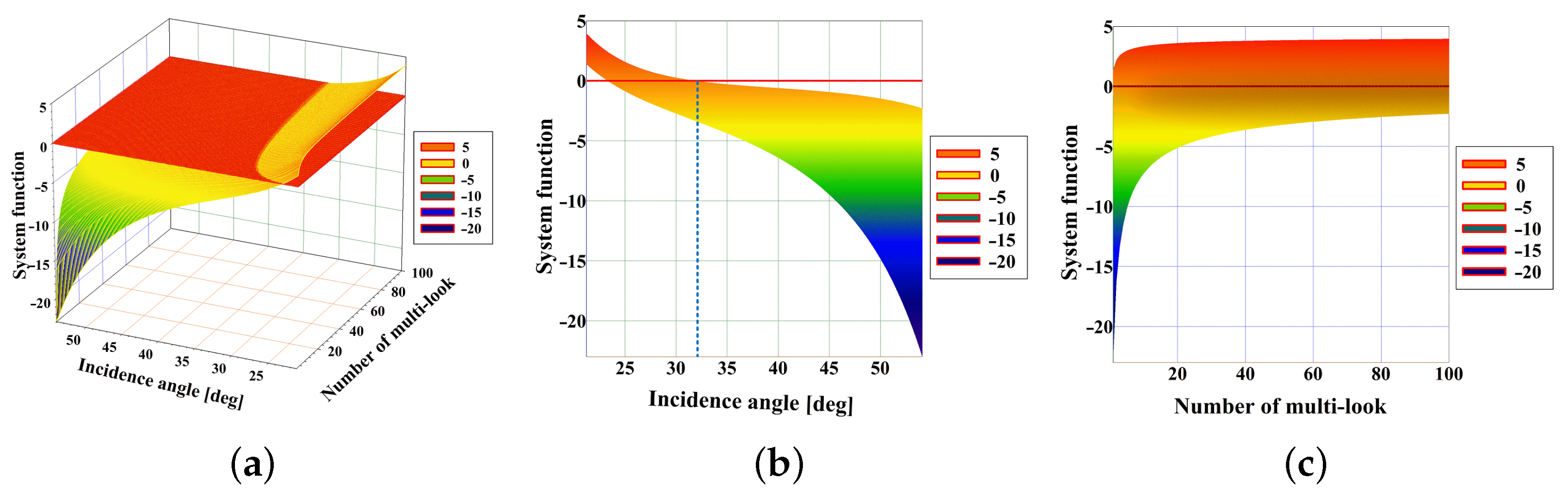
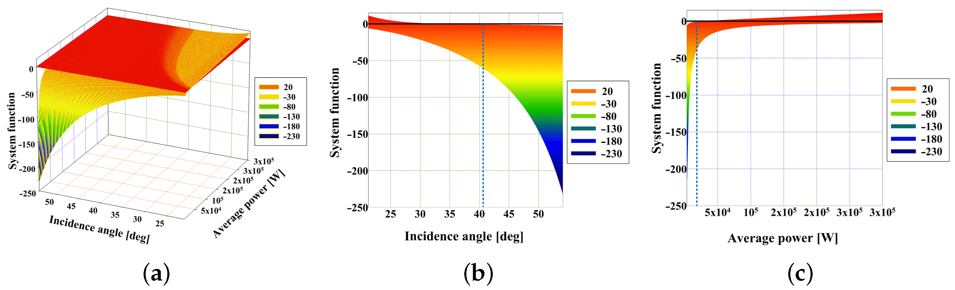
4.1. Experiments for Pure Water Ice

According to (23) and (24), system parameters in Table 2 and the system design process in Section 3, several simulation experiments are conducted to evaluate the influence of ϕ , L l o o k , P a v , H s a t and N b i t on the design of a spaceborne SAR system for distinguishing pure water ice from lunar regolith.
First, the simulation results of the system function varying with ϕ and L l o o k are shown in Figure 3, at the top of the next page. It can be derived that the system function is greater than zero when the incidence angle is less than 32 , and the different numbers of multi-looks are needed to distinguish the water ice from lunar regolith at different incidence angles.
Furthermore, the results that the system function changes with ϕ and P a v are obtained, as shown in Figure 4, in the middle of the next page. It can be seen that the minimum average transmitting power for the SAR system to distinguish lunar regolith and water ice is 22,000 W. The higher transmitting power places a higher requirement for the SAR system, which can be weakened by reducing the satellite height and signal bandwidth.
Moreover, an experiment is executed to evaluate the influence of satellite height H s a t on the SAR system function, as shown in Figure 5, at the bottom of the next page. It is obvious that the upper limit of the satellite height required by the system function greater than zero is about 58 km when the average transmitting power is 6000 W. At this point, the SAR system may be able to distinguish the water ice from lunar regolith at the incidence angle of less than 38 ° . These also indicate that the high energy requirement for the system function can be reduced by decreasing the satellite height.
The N b i t required by the receiver is also derived as shown in Figure 6. It can be seen that the digital collector with high N b i t can be used to distinguish the water ice from lunar regolith in terms of backscattering coefficients. This operation increases the volume of radar echo data. Fortunately, some advanced data compression methods and transmission systems [35,36] can solve this problem and provide assistance for lunar water ice exploration.

4.2. Experiments for Mixtures

More simulation experiments are executed based on (19), (24) and system parameters in Table 2 to evaluate the effects of ϕ , L l o o k , P a v and H s a t on the system design of spaceborne SAR under the conditions that the scale factors of water ice are 5% and 10%, respectively.
The results of the simulation experiments with the 5% scale factor of water ice are shown in Figure 7, Figure 8 and Figure 9 separately at the 12th page, and those with the 10% scale factor are shown in Figure 10, Figure 11 and Figure 12, respectively, at the 13th page. It can be obtained that based on the proposed method, the system parameters can be optimized to design the spaceborne SAR to collect radar data that can be used to detect the different amounts of lunar water ice. Since optimizing the SAR system parameters is not the focus of this paper, it is not detailed here.
The simulation experiments mainly evaluate the influence of ϕ , L l o o k , P a v , H s a t and N b i t on the capability of spaceborne SAR to detect water ice on the Moon. To obtain radar data to distinguish the dielectric constants of water ice and lunar regolith, and to estimate the water ice content, the parameters that meet the system performance requirements can be derived according to the system design process in Section 3.
In addition, the exploration of lunar water ice is further discussed in the following, which also indicates that the proposed SAR design method is of great significance.

5. Discussion

The PSRs are considered the primary containers of water ice on the Moon [1,2]. Before humans or robots locate and extract the water ice on the Moon, fundamental questions about the abundance and distribution of lunar water ice must be addressed.

5.1. Exploration of Water Ice by Non-Radar Techniques

For the first time in 2010, the LCROSS mission [5,37,38] detected the potential abundance of water and other volatiles (∼5 wt. % water). However, this impact method can only detect water ice beneath the Moon’s surface from a single location, rather than all PSRs that may have water ice. In 2017, Li and Milliken proposed to use a new thermal correction model and experimentally validated the relationship between absorption strength and water content to construct the first global quantitative maps of the lunar surface water derived from the Moon Mineralogy Mapper ( M 3 ) near-infrared reflectance data [39]. However, the second method can only be used to obtain the distribution of water on the Moon’s surface instead of under it. Moreover, the 3-micron band used by Li et al. [39] is related to both OH and H 2 O. Thus, it is still difficult to determine the relative content of OH and H 2 O on the surface of the Moon. Li’s result has also been challenged by other thermal correction methods [40,41], since the usage of other methods leads to different results than that of Li et al. Therefore, these water ice detection methods have drawbacks as mentioned before, and J. Lawrence proposed that some missions need to be accomplished in the next 50 years for the exploration of PSRs on the Moon [1]. He expressed that some new orbital measurements need to be completed, which would provide crucial new information to further explore the water ice on the Moon [1].
Figure 13 describes the characteristic of using the impact method to detect the lunar water ice. As can be seen, it is difficult for the impact method to detect water ice in multiple areas. Fortunately, the near-infrared [39,42] and neutron (the method of using the neutron spectrometer to detect the lunar water ice is dependent on the influx of galactic cosmic rays (GCR) that spall neutrons in the top meter of lunar regolith.) [7] spectrometers can make it. However, they can barely be used to observe the water ice under the Moon’s surface or in the areas without sunlight.

5.2. Advantage of Using SAR to Exploration Water Ice

With the advantages of day/night, all-weather, active detection, and penetration, SAR can be used to detect the water ice on and under the lunar surface at all locations [34]. According to the foregoing, it is difficult for the radar system to distinguish the dielectric constants of lunar regolith and water ice, and the spaceborne SAR system for the lunar water ice exploration in orbit does not take this into account. Thus to detect the water ice more accurately, the first step is to design a spaceborne SAR system that can collect the radar data used to distinguish the dielectric constants of lunar regolith and water ice. Based on this, the paper proposes an innovative design method for spaceborne SAR, which may be used in lunar water ice exploration. Compared with other techniques, SAR can achieve a high spatial resolution for water ice detection. Taking the simulation parameters in Table 2 as an example, the signal bandwidth is 300 MHz, corresponding to a range resolution of 0.5 m, so a spatial resolution of 2 m for water ice identification will be achieved if a 4-looks multiple-looking procedure is applied. It should also be noted that taking ground range projection into account will lead to a little worse spatial resolution.

5.3. Effect of Roughness on Detection

As mentioned before, CPR obtained from SAR images is an ambiguous indicator for the presence of water ice on the Moon, because the roughness of the surface will also lead to high CPR values [15]. The method of water ice identification developed in this paper is based on the difference in the dielectric constants of water ice and lunar regolith. Hence, the roughness of the surface will not make this method ambiguous. However, the Campbell model is accurate only when the surface has a slight roughness. In other words, the water ice detection in very rough regions using our method could be a challenging task.

5.4. Effect of Other Volatiles on Detection

Since this water ice detection method is based on the dielectric constant difference, it can also be used to identify other volatile species such as S, SO 2 , H 2 S, CO, and CO 2 mixed with water ice, if they have different dielectric constants in comparison with the lunar regolith. However, it will be more rigorous to design the radar system if the dielectric constant of the volatile has low contrast with that of lunar regolith. At the same time, the detection of water ice may fail if there exist other volatiles, of which the dielectric constants are close to that of water ice. Therefore, the dielectric constants of S, SO 2 , H 2 S, CO, and CO 2 ices (indicated by the LCROSS impact experiment [43]) should be considered carefully. The dielectric constants of solid S ( ε = 2.7 ) [44], solid H 2 S ( ε = 3.52 ) [45] and CO 2 ( ε = 2.25 + j 0.0045 ) [46] are very different from water ice, so these species of volatile would not make the detection of water ice ambiguous. The dielectric constants of mixtures of different volatiles are not easy to be estimated. If the dielectric constant of the mixture is very close to that of pure water ice, then this mixture can not be distinguished from water ice by our synthetic aperture radar (SAR) method. Moreover, Table 2 in [43] reports the mass fractions of compounds in polar regolith, e.g., H 2 O (5.6 wt. %), S (<0.3 wt. %), SO 2 (0.2 wt. %), H 2 S (0.2 wt. %), CO (0.08 wt. %) and CO 2 (0.04 wt. %). Compared with water ice, the content of other volatiles is low. Therefore, it can be expected that other volatiles will not affect the detection of pure water ice.

5.5. Effect of Variable Dielectric Constant of Lunar Regolith on Detection

In fact, the dielectric constant of lunar regolith can also be a variable. According to Carrier et al. [47], laboratory measurements of lunar regolith samples show that the real part of the dielectric constant, ε r e g o l i t h , is strongly dependent upon bulk density and is largely independent of chemical composition, and the imaginary part is strongly dependent on the bulk density and composition (in particular, the abundance of ilmenite). For more details, the reader is referred to [47]. In the craters in PSRs, 2.7 + j 0.003 used in this study is a reasonable value for the dielectric constant of lunar regolith. The dielectric constant of lunar regolith is smaller than that of water ice most of the time, but it ( ε r e g o l i t h ) can approach and even exceed the dielectric constant of water ice when the lunar regolith gets denser. Therefore, more detailed constraints about the dielectric constant or bulk density of the lunar regolith in PSRs should be proposed via further studies. Other water ice exploration techniques, such as near-infrared and neutron spectroscopy, are indispensable, as complements and validations of the SAR method proposed in this paper.

5.6. Limitation of the Campbell Model

It should be noticed that when the resolution of the radar data is changed, the scattering characteristic of the lunar surface in the radar image may be different. Therefore, the Campbell model may not be accurate enough for high spatial resolution SAR, because this model is established based on the radar data with a spatial resolution lower than 10 m. Moreover, the Campbell model is accurate only when the subsurface of the lunar regolith has a very slight roughness. As Fa [20] reports that the subsurface of the lunar regolith may have a 1 ° RMS (root mean square) slope, which corresponds to a slight roughness, the Campbell model can still be useful at some times. An improved model in [29] based on the Campbell model can be applied in a rougher subsurface and larger incidence angle, because it uses the SPM (small perturbation approximation) to characterize the rough subsurface scattering and accounts for the topography. Fortunately, both the Campbell model and the improved one have similar formulas, so a substitution between these two models will not change the main conclusion in this paper. It should also be noted that both the Campbell model and the improved model do not take the scattering contributions from the surface and volume into account. Though a polarimetric scattering model in [20] can describe the lunar regolith scattering more accurately, its form is too complex to give a further derivation. In the future, if a simpler analytic model about the lunar surface scattering is applicable, similar steps can be taken to obtain the system function for the design of SAR.

6. Conclusions

The premise of the accurate detection of possible water ice and mapping of its distribution in the lunar PSRs, is to obtain radar data that can be used to distinguish the water ice and lunar regolith. As such, the paper based on the Campbell model and SAR radiometric resolution proposes an innovative system design method for spaceborne SAR to realize the distinction between the water ice and lunar regolith with a small difference in the dielectric constants. This method is mainly used to evaluate the influence of the radar incidence angle, the number of multi-looks, quantization accuracy of receivers, average transmitting power, and so on, on the capability of the spaceborne SAR system to distinguish pure water ice and lunar regolith, and to estimate the content of water ice on the Moon. Based on the method, some simulation experiments were executed. The results indicate that to detect pure water ice from the lunar regolith, there are upper limits for the incidence angle and satellite height, and lower limits for the average power and the number of multi-looks. For example, if the average transmitting power and the number of multi-looks are P a v = 6 kW and L l o o k = 10 , the incidence angle should be no more than 38 ° and the satellite height should be lower than 58 km. Conversely, the average transmitting power should be higher than 22 kW when the satellite height is fixed at 100 km. Moreover, based on the system parameters in Table 2, to detect 5 and 10 wt. % water ice fraction from the lunar regolith, the incidence angle should be no more than 33 ° and 34 ° , respectively, and the number of multi-looks should be larger than four when the average transmitting power and satellite height are 10 kW and 100 km. In short, the results indicate that the proposed SAR design method may be helpful for lunar water ice exploration. Besides general radar equation constraints, this paper points out that one more constraint of water ice detection, i.e., the system function proposed in the paper, should be added to guide the design of SAR for lunar water ice exploration.

Author Contributions

Conceptualization, Y.Z. and R.W.; methodology, Y.Z. and M.L.; software, Y.Z.; validation, Y.Z.; writing—original draft preparation, Y.Z. and S.C.; writing—review and editing, Y.Z., F.Z. and S.C.; visualization, Y.Z. and S.C.; project administration, R.W.; funding acquisition, R.W. All authors have read and agreed to the published version of the manuscript.

Funding

This work was supported in part by the National Science Fund for Distinguished Young Scholars under Grant 61825106 and by the National Science Fund under Grant 61701479.

Data Availability Statement

Not applicable.

Conflicts of Interest

The authors declare no conflict of interest.

References

  1. Lawrence, D. A tale of two poles: Toward understanding the presence, distribution, and origin of volatiles at the polar regions of the Moon and Mercury. J. Geophys. Res. Planets 2017, 122, 21–52. [Google Scholar] [CrossRef]
  2. Watson, K.; Murray, B.; Brown, H. On the possible presence of ice on the Moon. J. Geophys. Res. 1961, 66, 1598–1600. [Google Scholar] [CrossRef] [Green Version]
  3. Feldman, W.; Maurice, S.; Binder, A.; Barraclough, B.; Elphic, R.; Lawrence, D. Fluxes of fast and epithermal neutrons from Lunar Prospector: Evidence for water ice at the lunar poles. Science 1998, 281, 1496–1500. [Google Scholar] [CrossRef] [PubMed] [Green Version]
  4. Feldman, W.; Maurice, S.; Lawrence, D.; Little, R.; Lawson, S.; Gasnault, O.; Wiens, R.; Barraclough, B.; Elphic, R.C.; Prettyman, T. Evidence for Water Ice Near the Lunar Poles. J. Geophys. Res. 2001, 106, 23231–23252. [Google Scholar] [CrossRef]
  5. Neish, C.; Bussey, D.; Spudis, P.; Marshall, W.; Thomson, B.; Patterson, G.; Carter, L. The nature of lunar volatiles as revealed by mini-RF observations of the LCROSS impact site. J. Geophys. Res. 2011, 116, E01005. [Google Scholar] [CrossRef]
  6. Malphrus, B.; Polina, Z.; Kevin, B.; David, F.; Cliff, B.; Terry, H.; Matthew, G.; Michael, T.; Pamela, C. The lunar IceCube EM-1 mission: Prospecting for lunar water ice. In Proceedings of the 42nd COSPAR Scientific Assembly, Pasadena, CA, USA, 14–22 July 2018. [Google Scholar]
  7. Mitrofanov, I.; Sanin, A.; Boynton, W.; Chin, G.; Garvin, J.; Golovin, D.; Evans, L.; Harshman, K.; Kozyrev, A.; Litvak, M.; et al. Hydrogen mapping of the lunar South Pole using the LRO neutron detector experiment LEND. Science 2010, 330, 483–486. [Google Scholar] [CrossRef]
  8. Nozette, S.; Rustan, P.; Pleasance, L.; Kordas, J.; Lewis, I.; Park, H.; Priest, R.; Horan, D.; Regeon, P.; Lichtenberg, C.; et al. The Clementine Mission to the Moon-Scientific overview. Science 1994, 266, 1835–1839. [Google Scholar] [CrossRef] [Green Version]
  9. Nozette, S.; Lichtenberg, C.; Spudis, P.; Bonner, R.; Ort, W.; Malaret, E.; Robinson, M.; Shoemaker, E. The Clementine bi-static radar experiment. Science 1996, 274, 1495–1498. [Google Scholar] [CrossRef] [Green Version]
  10. Stacy, N.; Campbell, D.; Ford, P. Arecibo radar mapping of the lunar poles: A search for ice deposits. Science 1997, 276, 1527–1530. [Google Scholar] [CrossRef] [Green Version]
  11. Stacy, N.; Campbell, D.; Ford, P. The possibility of ice on the Moon—Response. Science 1997, 278, 145. [Google Scholar]
  12. Campbell, D.; Campbell, B.; Carter, L.; Margot, J.; Stacy, N. No evidence for thick deposits of ice at the lunar south pole. Nature 2006, 443, 835–837. [Google Scholar] [CrossRef] [PubMed]
  13. Spudis, P.; Bussey, D.; Baloga, S.; Butler, B.; Carl, D.; Carter, L.; Chakraborty, M.; Elphic, R.; Gillis-Davis, J.; Goswami, J. Initial results for the north pole of the Moon from Mini-SAR, Chandrayaan-1 mission. Geophys. Res. Lett. 2010, 37, L06204. [Google Scholar] [CrossRef]
  14. Spudis, P.; Bussey, D.; Baloga, S.; Cahill, J.; Glaze, L.; Patterson, G.; Raney, R.; Thompson, T.; Thomson, B.; Ustinov, E. Evidence for water ice on the Moon: Results for anomalous polar craters from the LRO Mini-RF imaging radar. J. Geophys. Res. Planets 2013, 118, 2016–2029. [Google Scholar] [CrossRef]
  15. Fa, W.; Cai, Y. Circular polarization ratio characteristics of impact craters from Mini-RF observations and implications for ice detection at the polar regions of the Moon. J. Geophys. Res. Planets 2013, 118, 1582–1608. [Google Scholar] [CrossRef]
  16. Patterson, G.; Stickle, A.; Turner, F.; Jensen, J.; Bussey, D.; Spudis, P.; Espiritu, R.; Schulze, R.; Yocky, D.; Wahl, D.; et al. Bistatic radar observations of the Moon using Mini-RF on LRO and the Arecibo Observatory. Icarus 2016, 283, 2–19. [Google Scholar] [CrossRef]
  17. Putrevu, D.; Das, A.; Vachhani, J.G.; Trivedi, S.; Misra, T. Chandrayaan-2 dual-frequency SAR: Further investigation into lunar water and regolith. Adv. Space Res. 2016, 57, 627–646. [Google Scholar] [CrossRef]
  18. Shanmugam, M.; Patel, A.; Vadawale, S.V.; Acharya, Y.B.; Goyal, S.K. Characterization of high count rate capability of Solar X-ray Monitor on-board Chandrayaan-2—The second Indian mission to the Moon. In Proceedings of the 2013 IEEE Nuclear Science Symposium and Medical Imaging Conference (2013 NSS/MIC), Seoul, Korea, 27 October–2 November 2013; pp. 1–7. [Google Scholar]
  19. Yue, Z.; Johnson, B.; Minton, D.; Melosh, H.; Di, K.; Hu, W.; Liu, Y. Projectile remnants in central peaks of lunar impact craters. Nat. Geosci. 2013, 6, 435–437. [Google Scholar] [CrossRef]
  20. Fa, W.; Wieczorek, M.; Heggy, E. Modeling polarimetric radar scattering from the lunar surface: Study on the effect of physical properties of the regolith layer. J. Geophys. Res. Planets 2011, 116, 58–66. [Google Scholar] [CrossRef]
  21. Mishra, P.; Kumar, S.; Singh, D. An approach to determine possible existence of water ice deposits on lunar craters using minisar data. In Proceedings of the 2013 IEEE International Geoscience and Remote Sensing Symposium—IGARSS, Melbourne, VIC, Australia, 21–26 July 2013; pp. 21–24. [Google Scholar]
  22. Mishra, P.; Kumar, S.; Singh, D. An Approach for Finding Possible Presence of Water Ice Deposits on Lunar Craters Using MiniSAR Data. IEEE J. Sel. Top. Appl. Earth Obs. Remote Sens. 2015, 8, 30–38. [Google Scholar] [CrossRef]
  23. Thompson, T.; Ustinov, E.; Heggy, E. Modeling radar scattering from icy lunar regoliths. In Proceedings of the 2011 XXXth URSI General Assembly and Scientific Symposium, Istanbul, Turkey, 13–20 August 2011; pp. 1–2. [Google Scholar]
  24. Campbell, B.A. High circular polarization ratios in radar scattering from geologic targets. J. Geophys. Res. 2012, 117, 1–9. [Google Scholar] [CrossRef] [Green Version]
  25. Liu, J.; Ren, X.; Yan, W.; Li, C.; Zhang, H.; Jia, Y.; Zeng, X.; Chen, W.; Gao, X.; Liu, D.; et al. Descent trajectory reconstruction and landing site positioning of Chang’E-4 on the lunar farside. Nat. Commun. 2019, 10, 4229. [Google Scholar] [CrossRef] [PubMed] [Green Version]
  26. Krieger, G.; Moreira, A.; Fiedler, H.; Hajnsek, I.; Werner, M.; Younis, M.; Zink, M. TanDEM-X: A Satellite Formation for High-Resolution SAR Interferometry. IEEE Trans. Geosci. Remote Sens. 2017, 45, 3317–3341. [Google Scholar] [CrossRef] [Green Version]
  27. Campbell, B.A.; Grant, J.A.; Maxwell, T. Radar penetration in Mars Analog Environments. In Proceedings of the 33rd Annual Lunar Planetary Science Conference, Houston, TX, USA, 11–15 March 2002. [Google Scholar]
  28. Calla, O.P.N.; Mathur, S.; Gadri, K.L. Quantification of Water Ice in the Hermite-A Crater of the Lunar North Pole. IEEE Geosci. Remote Sens. Lett. 2016, 13, 926–930. [Google Scholar] [CrossRef]
  29. Liu, N.; Ye, H.; Jin, Y. Dielectric Inversion of Lunar PSR Media with Topographic Mapping and Comment on “Quantification of Water Ice in the Hermite-A Crater of the Lunar North Pole”. IEEE Geosci. Remote Sens. Lett. 2017, 14, 1444–1448. [Google Scholar] [CrossRef]
  30. Park, H.; Camps, A.; Choi, M.G.; Kim, Y. Radiometric Resolution of Motion-Induced Synthetic Aperture Radiometer. IEEE Geosci. Remote Sens. Lett. 2011, 8, 715–719. [Google Scholar] [CrossRef]
  31. Bonafoni, S.; Alimenti, F.; Roselli, L. An Efficient Gain Estimation in the Calibration of Noise-Adding Total Power Radiometers for Radiometric Resolution Improvement. IEEE Trans. Geosci. Remote Sens. 2018, 56, 5289–5298. [Google Scholar] [CrossRef]
  32. Marquez-Martinez, J.; Mittermayer, J.; Rodriguez-Cassola, M. Radiometric resolution optimization for future SAR systems. In Proceedings of the 2004 IEEE International Geoscience and Remote Sensing Symposium, Anchorage, AK, USA, 20–24 September 2007; pp. 1738–1741. [Google Scholar]
  33. Frost, V. Probability of Error And Radiometric Resolution for Target Discrimination in Radar Images. IEEE Trans. Geosci. Remote Sens. 1984, GE-22, 121–125. [Google Scholar] [CrossRef]
  34. Massonnet, D.; Souyris, J. Imaging with Synthetic Aperture Radar; Taylor and Francis: New York, NY, USA, 2008; ISBN 9780429147807. [Google Scholar]
  35. Liang, Y.; Li, Y. An Efficient and Robust Data Compression Algorithm in Wireless Sensor Networks. IEEE Commun. Lett. 2014, 18, 439–442. [Google Scholar] [CrossRef]
  36. Noh, Y.; Yom, I. A Linear GaN High Power Amplifier MMIC for Ka-Band Satellite Communications. IEEE Microw. Compon. Lett. 2016, 26, 619–621. [Google Scholar] [CrossRef]
  37. Colaprete, A.; Schultz, P.; Heldmann, J.; Wooden, D.; Shirley, M.; Ennico, K.; Hermalyn, B.; Marshall, W.; Ricco, A.; Elphic, R.C.; et al. Detection of water in the LCROSS Ejecta Plume. Science 2010, 330, 463–468. [Google Scholar] [CrossRef] [Green Version]
  38. Colaprete, A.; Elphic, R.; Heldmann, J.; Ennico, K. An overview of the Lunar Crater Observation and Sensing Satellite (LCROSS). Space Sci. Rev. 2012, 167, 3–22. [Google Scholar] [CrossRef]
  39. Li, S.; Milliken, R. Water on the surface of the Moon as seen by the Moon Mineralogy Mapper: Distribution, abundance, and origins. Sci. Adv. 2017, 3, e1701471. [Google Scholar] [CrossRef] [PubMed] [Green Version]
  40. Bandfield, J.L.; Poston, M.J.; Klima, R.L.; Edwards, C.S. Widespread distribution of OH/H2O on the lunar surface inferred from spectral data. Nat. Geosci. 2018, 11, 173–177. [Google Scholar] [CrossRef] [PubMed]
  41. Wöhler, C.; Grumpe, A.; Berezhnoy, A.A.; Shevchenko, V.V. Time-of-day-dependent global distribution of lunar surficial water/hydroxyl. Sci. Adv. 2017, 3, e1701286. [Google Scholar] [CrossRef] [Green Version]
  42. Pieters, C.; Goswami, J.; Clark, R.; Annadurai, M.; Boardman, J.; Buratti, B.; Combe, J.; Dyar, M.; Green, R.; Head, J.; et al. Character and spatial distribution of OH/H2O on the surface of the Moon seen by M3 on Chandrayaan. Science 2010, 326, 568–572. [Google Scholar] [CrossRef]
  43. Berezhnoy, A.A.; Kozlova, E.A.; Sinitsyn, M.P.; Sinitsyn, A.; Shevchenko, V. Origin and stability of lunar polar volatiles. Adv. Space Res. 2012, 50, 1638–1646. [Google Scholar] [CrossRef]
  44. Physical Properties of Sulphur. Available online: http://sulphur.atomistry.com/physical_properties_sulphur.html (accessed on 31 March 2022).
  45. Havriliak, S.; Swenson, R.W.; Cole, R.H. Dielectric Constants of Liquid and Solid Hydrogen Sulfide. J. Chem. Phys. 1955, 23, 134–135. [Google Scholar] [CrossRef] [Green Version]
  46. Pettinelli, E.; Cosciotti, B.; Di Paolo, F.; Lauro, S.E.; Mattei, E.; Orosei, R.; Vannaroni, G. Dielectric properties of Jovian satellite ice analogs for subsurface radar exploration: A review. Rev. Geophys. 2015, 53, 593–641. [Google Scholar] [CrossRef] [Green Version]
  47. Carrier, W.D.; Olhoeft, G.R.; Mendell, W. Physical Properties of the Lunar Surface. In Lunar Source Book; Heiken, G.H., Vaniman, D.T., French, B.M., Eds.; Cambridge University Press: New York, NY, USA, 1991; pp. 475–594. [Google Scholar]
Figure 1. The main flow of the newly defined SAR system function for lunar water ice exploration is presented based on the Campbell model and the requirement of SAR radiometric resolution.
Remotesensing 14 02148 g001
Figure 2. Schematic diagram of SAR system design for lunar water ice exploration. The blue, red, black, and light green ellipses represent the initial parameter values, constraint, final parameter values, and system parameters, respectively, and the orange circle denotes the calculation of the SAR system function.
Remotesensing 14 02148 g002
Figure 3. (a) The SAR system function varies with the incidence angle ϕ and the number of multi-looks L l o o k when the average transmitting power and satellite height are P a v = 100,000 W and H s a t = 100 km. (b,c) are the simulation results of the system function changing with ϕ and L l o o k , separately.
Remotesensing 14 02148 g003
Figure 4. (a) When the number of multi-looks and the satellite height are L l o o k = 10 and H s a t = 100 km, the system function changes with the incidence angle ϕ and average power P a v . (b,c) are the simulation results of the system function changing with ϕ and P a v , separately.
Remotesensing 14 02148 g004
Figure 5. (a) When the average transmitting power and the number of multi-looks are P a v = 6000 W and L l o o k = 10, the system function changes with the incidence angle ϕ and satellite height H s a t . (b,c) are the simulation results of the system function varying with ϕ and H s a t , separately.
Remotesensing 14 02148 g005
Figure 6. The variation in the quantization bit rate N b i t with the incidence angle ϕ .
Remotesensing 14 02148 g006
Figure 7. (a) The SAR system function varies with the incidence angle ϕ and the number of multi-looks L l o o k when the average transmitting power, satellite height, and scale factor of water ice are P a v = 100,000 W, H s a t = 100 km and 5%. (b,c) are the simulation results of the system function changing with ϕ and L l o o k , separately.
Remotesensing 14 02148 g007
Figure 8. (a) When the number of multi-looks, satellite height, and scale factor of water ice are L l o o k = 10, H s a t = 100 km and 5%, the system function changes with the incidence angle ϕ and average power P a v . (b,c) are the simulation results of the system function changing with ϕ and P a v , respectively.
Remotesensing 14 02148 g008
Figure 9. (a) When the average transmitting power, the number of multi-looks, and scale factor of water ice are P a v = 6000 W, L l o o k = 10 and 5%, the system function changes with the incidence angle ϕ and satellite height H s a t . (b,c) are the simulation results of the system function varying with ϕ and H s a t , separately.
Remotesensing 14 02148 g009
Figure 10. (a) The SAR system function varies with the incidence angle ϕ and the number of multi-looks L l o o k when the average transmitting power, satellite height, and scale factor of water ice are P a v = 100,000 W, H s a t = 100 km and 10%. (b,c) are the simulation results of the system function changing with ϕ and L l o o k , separately.
Remotesensing 14 02148 g010
Figure 11. (a) When the number of multi-looks, satellite height, and scale factor of water ice are L l o o k = 10, H s a t = 100 km and 10%, the system function changes with the incidence angle ϕ and average power P a v . (b,c) are the simulation results of the system function changing with ϕ and P a v , respectively.
Remotesensing 14 02148 g011
Figure 12. (a) When the average transmitting power, the number of multi-looks, and scale factor of water ice are P a v = 6000 W, L l o o k = 10 and 10%, the system function changes with the incidence angle ϕ and satellite height H s a t . (b,c) are the simulation results of the system function varying with ϕ and H s a t , separately.
Remotesensing 14 02148 g012
Figure 13. South polar regions of the Moon. The LCROSS [5] impact region is shown by a red circle.
Remotesensing 14 02148 g013
Table 1. The dielectric constants of the water ice and lunar regolith on the Moon [15].
ComponentsDielectric Constants
Water ice ε i c e = 3.15 + j 0.001
Lunar regolith ε r e g = 2.70 + j 0.003
Table 2. The system parameters used for the simulation experiments to evaluate the influence of the incidence angle, the number of multi-looks, transmitting power, quantization accuracy of receivers, and so on on the design of spaceborne SAR system for lunar water ice exploration.
ParametersValues
Satellite height ( H s a t )15∼100 km
Satellite velocity ( V s )1671.8∼1633.5 m/s
Carrier frequency ( f c )1.25 GHz
Signal bandwidth ( B r )300 MHz
Field-of-View ( ϕ )[ 20 ° , 50 ° ]
NE σ 0 −25 dB
Noise factor ( F n )1.7 dB
System loss ( L s )1.5 dB
Average power ( P a v )3000∼300,000 W
The Number of multi-looks ( L l o o k )1∼150
Network temperature ( T o )293 K
Dynamic range of receivers ( D R r )60 dB
Publisher’s Note: MDPI stays neutral with regard to jurisdictional claims in published maps and institutional affiliations.

