Article

An Improved Pedestrian Navigation Method Based on the Combination of Indoor Map Assistance and Adaptive Particle Filter

1
College of Automation Engineering, Nanjing University of Aeronautics and Astronautics, Nanjing 210016, China
2
Navigation Research Center, School of Automation Engineering, Nanjing University of Aeronautics and Astronautics, Nanjing 211106, China
3
School of Railway Transportation, Shanghai Institute of Technology, Shanghai 201418, China
*
Author to whom correspondence should be addressed.
Remote Sens. 2022, 14(24), 6282; https://doi.org/10.3390/rs14246282
Submission received: 26 September 2022 / Revised: 1 December 2022 / Accepted: 8 December 2022 / Published: 11 December 2022

Abstract

:
At present, the traditional indoor pedestrian navigation methods mainly include pedestrian dead reckoning (PDR) and zero velocity update (ZUPT), but these methods have the problem of error divergence during long time navigation. To solve this problem, under the condition of not relying on the active sensing information, combined with the characteristics of particles “not going through the wall” in the indoor map building structure, an improved adaptive particle filter (PF) based on the particle “not going through the wall” method is proposed for pedestrian navigation in this paper. This method can restrain the error divergence of the navigation system for a long time. Compared to the traditional pedestrian navigation method, based on the combination of indoor map assistance (MA) and particle filter, a global search method based on indoor MA is used to solve the indoor positioning problem under the condition of the unknown initial position and heading. In order to solve the problem of low operation efficiency caused by the large number of particles in PF, a calculation method of adaptively adjusting the number of particles in the process of particle resampling is proposed. The results of the simulation data and actual test data show that the proposed indoor integrated positioning method can effectively suppress the error divergence problem of the navigation system. Under the condition that the total distance is more than 415.44 m in the indoor environment of about 2600 m2, the average error and the maximum error of the position are less than two meters relative to the reference point.

1. Introduction

With the progress of urbanization, the indoor environment has become an important place for human production and life. Indoor pedestrian navigation technology has been widely considered and studied by scholars in disaster relief and rescue, medical search and rescue, public security, anti-terrorism and other fields. Providing accurate navigation and positioning capabilities for pedestrians in indoor working environments is the basis for achieving indoor rescue work. In indoor working environments, the signals of global positioning system (GPS) [1], Beidou and other global navigation satellite systems (GNSS) [2] are seriously blocked, which makes it difficult to play the role of normal navigation and positioning and the incapacity to provide accurate navigation and positioning function for pedestrians. Therefore, it is necessary to carry out research on the pedestrian navigation method in the indoor satellite failure environment.
The current indoor pedestrian navigation technology mainly includes active navigation and passive navigation. Active navigation means that navigation and positioning must be carried out with the help of sensors other than itself, including ultra wide band (UWB) [3], wireless fidelity (Wi-Fi) [4], bluetooth (BT) [5], ZigBee [6], radio frequency identification (RFID) [7], near field communication (NFC) [8] and other methods. While the positioning error of the active navigation algorithm does not accumulate over time, it is greatly affected by the indoor environment, obstacles, multipath propagation [9,10] and other environmental factors. It is necessary to arrange the source base station in advance and build a fingerprint database. The cost of construction and maintenance is high. In addition, the indoor rescue site is often accompanied by problems such as the unavailability of beacons caused by power system interruption. The relevant navigation and positioning technology is difficult to meet the availability requirements of indoor rescue positioning. Passive navigation refers to a navigation and positioning method that only relies on its own sensors, without relying on external sensor information sources. It mainly includes the methods of simultaneous localization and mapping (SLAM) based on the laser radar sensor [11] and visual sensor [12] (monocular camera, binocular camera, depth camera), and the methods based on inertial measurement unit (IMU). For the indoor rescue navigation and positioning system with high real-time requirements, there are shortcomings, such as the laser radar remaining unchanged, and the visual sensor may be affected by the indoor environment. As it is inconvenient for pedestrians to carry lidars, and visual sensors may be affected by indoor environment, these sensors cannot meet the needs of pedestrian navigation and positioning system for indoor rescue in actual use. With the development of technology, the micro electro–mechanical system (MEMS) [13] has been continuously improved and developed. As a kind of autonomous navigation and positioning equipment, a wearable inertial sensor based on MEMS technology has been widely studied in indoor pedestrian navigation. It only needs to fix the IMU on the human body and calculate pedestrian navigation parameters by collecting IMU data to realize autonomous navigation and positioning.
The pedestrian navigation algorithms based on IMU are mainly divided into two categories: The PDR algorithm and ZUPT algorithm. The pedestrian navigation method based on PDR estimates the step length, step number, heading and other parameters of the pedestrian in the walking process by collecting the acceleration, angular velocity and other data of the pedestrian, and calculates the pedestrian motion trace. In 2017, Dina [14] proposed a method to estimate the step length through the information of leg and foot inertial sensors of two navigation systems. In 2018, Xu [15] studied the PDR navigation algorithm based on handheld mobile phones. In order to improve the step length estimation accuracy of the algorithm for different users, she proposed a step length detection method based on state transition and a step length estimation method based on neural networks. In 2020, Ding [16] proposed a PDR navigation algorithm based on the relationship between waist inertial data and step length. Based on the ZUPT algorithm, the inertial sensor is installed on the foot. According to the algorithm, the velocity of the foot is zero in theory during the period of time when the foot contacts the ground during periodic movement, and the velocity during this period is used as the observation quantity to periodically correct the position and velocity of the human. In 2016, Ruppelt [17] proposed a navigation and positioning technology about ZUPT detection based on the finite state machine. It was used to analyze the gait cycle of human foot mounted IMU, which could detect the zero velocity interval more accurately. In 2017, Hsu [18] proposed a sensor fusion technology based on a two-stage quaternion extended Kalman filter for the inertial sensor cumulative error, and the error between the starting point and the end point was 2.01%. In 2018, Suresh [19] proposed the method of combining the ZUPT and the high pass filter. He applied the high pass filter to the complementary filtering, reducing the error drift of the angular velocity. In 2021, Abdallah [20] proposed a foot-mounted and synthetic aperture indoor navigation method based on inertial/ZUPT/depth neural network, which reduced the accumulated error of inertial navigation system through the integrated navigation algorithm based on ZUPT. From the working principle, the pedestrian navigation system (PNS), based only on inertial sensors, will diverge after a long time of operation.
The error of PNS relying only on inertial sensors will diverge over time. To solve this problem, scholars have studied a variety of methods to correct the navigation error. In 2016, Ilyas [21] studied the indoor geomagnetic assisted pedestrian navigation. A large amount of information interferes with the magnetometer, resulting in magnetic information distortion. In this regard, a magnetic anomaly detection method is proposed to compensate the abnormal data. In 2018, Song [22] proposed a two-stage Kalman filter, in which a magnetic sensor is installed at the waist and an inertial sensor is installed at the foot. Compared to the traditional pedestrian navigation method based on ZUPT, the error is reduced by 30%. In 2016, Diez [23] proposed an improved heuristic drift elimination algorithm (iHDE) to install the inertial sensor on the wrist. Compared to the algorithm, iHDE reduces the error by 95%. In 2018, Muhammad [24] used the indoor corridor for heading correction and proposed an HDE algorithm based on waist heading. The author divided the 360-degree heading into 16 equal sectors. When pedestrians moved along the orthogonal corridor direction or the main heading, the algorithm corrected the heading. If the motion trace is a curve or not moving along the main heading, no course correction will be made. In 2021, Kim [25] proposed a topological map construction method based on tge architectural plan and sensors to solve the problem that it took a lot of time to create indoor maps in real time. This method can provide a safe path, and the indoor plan can be updated more easily in the future, even if the internal structure of the building changes. Since 2009, the German Aerospace Center has studied the navigation method based on Foot SLAM [26,27], which is only based on inertial sensors and can maintain the navigation accuracy for a long time. References [28,29] combined indoor map and PF to modify the pedestrian navigation results obtained by the inertial sensor solution. This method greatly improves the navigation accuracy, but the computational efficiency is low. As the indoor geomagnetic interference is large, and the auxiliary navigation effect is not good, the HDE method needs to obtain indoor environmental constraint features in advance. The Foot SLAM method needs to form a closed loop of motion trajectory, which has great limitations in practical applications. For the MA method, the indoor architectural plan is relatively easy to obtain, and navigation and positioning are realized by combining the indoor map with PF.
For the PNS relying only on inertial sensors, in order to effectively solve the needs of pedestrian autonomous navigation under special tasks such as indoor rescue, this paper proposes an improved pedestrian navigation positioning method based on the combination of indoor MA and adaptive PF (IMAPF). In order to solve the problem of high precision localization when pedestrians enter an unfamiliar environment with unknown initial position and heading, a global search method based on MA is proposed. Aiming at the problem that a large number of particle operations are required under the unknown initial position and heading, which leads to low computational efficiency, an adaptive particle number calculation method is proposed. It solves the problem of high-precision navigation and positioning of indoor pedestrians for a long time and the positioning problem under the unknown initial position and heading, and improves the computational efficiency, accuracy and reliability of the indoor pedestrian navigation system.
The structure of this paper is as follows: Section 2 describes the algorithm in detail. In Section 3, the proposed algorithm is verified by the simulation and experiment. Section 4 discusses the results of the experimental activities proposed. Finally, Section 5 concludes the paper.

2. Materials and Methods

2.1. Proposed System Scheme

In order to solve the error divergence problem of pedestrian navigation and positioning system for a long time, on the premise of no other external sensors, a pedestrian navigation and positioning method based on the combination of indoor IMAPF is proposed to constrain and correct the position and heading change information calculated by the navigation system through the constraint relationship between the indoor map information and the position and heading calculated by the inertial navigation. The frame of the designed integrated navigation and positioning method is shown in Figure 1.
The algorithm proposed in this paper is as follows: Firstly, through the dead reckoning module [30], a PNS based on foot-mounted ZUPT is established, and the navigation system is corrected by taking the difference between the heading change of foot and heading change of waist in one step as the observation, taking the physical distance between two adjacent zero velocity intervals as the step length, and then the heading change is obtained by integrating the waist angular velocity with time. Then, through the indoor map processing module, the indoor architectural plan is binarized, and then the image is simplified to obtain the available map. Establish a PF model, input the step length, heading change and indoor map obtained from the above two modules into the PF. First, initialize the position and heading of the particle set respectively according to the known or unknown initial position and heading of pedestrian navigation, detect whether particles “going through the wall”, delete “illegal particles” or retain “legal particles”, and calculate the particle normalization weight according to the sequential importance sampling. Secondly, the effective value of the particles is calculated to determine whether resampling is required. When resampling is required, the adaptive particle number is calculated to update the current state estimation value. Then the pedestrian position at the current time is solved, and the motion trace obtained from the solution is projected into the indoor map.

2.2. Pedestrian Navigation Method Based on Indoor MA and PF

2.2.1. Theoretical Model of Algorithm

(1)
Pedestrian navigation model based on dead reckoning
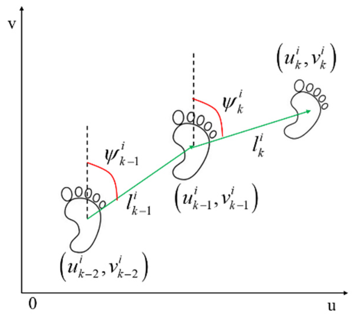
Figure 2 is the schematic diagram of the pedestrian motion trace update.
The state transition equation of particle filter of PDR can be obtained as
ψ k i = ψ k 1 i + Δ ψ k i u k i = u k 1 i + l k i sin ψ k i v k i = v k 1 i + l k i cos ψ k i
In Equation (1), the system state quantity is the pedestrian position coordinate u k i , v k i in the two-dimensional plane. The control quantity of the system is Δ ψ k i and l k i , where Δ ψ k i is the heading change, and l k i is the step length. Subscript k is step k -th step, and superscript i is the i -th particle. The particle contains the possible two-dimensional position and heading at the current time. The position of the particle is corrected by constantly adjusting the particle weight and the two-dimensional position.
The control quantity equation of the particle filter based on PDR is:
l ^ k = l k + γ l k Δ ψ ^ k = Δ ψ k + γ ψ k
In Equation (2), γ l k and γ ψ k represent step noise and heading change noise, respectively, which all obey the Gaussian distribution.
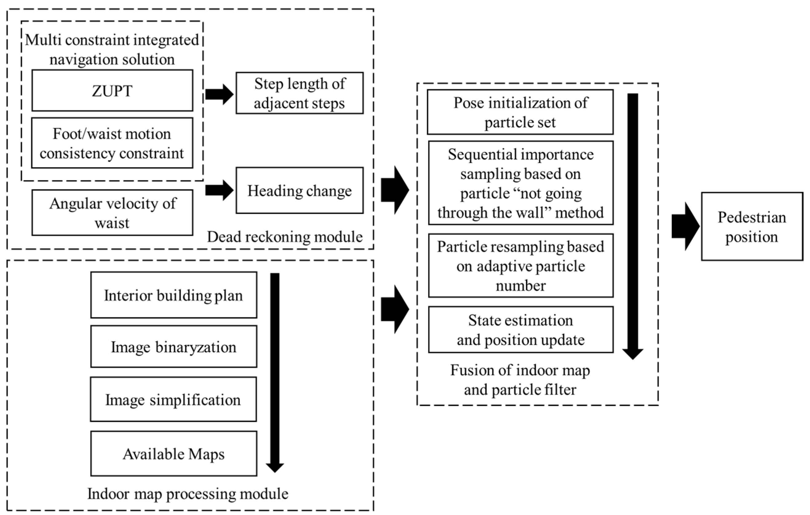
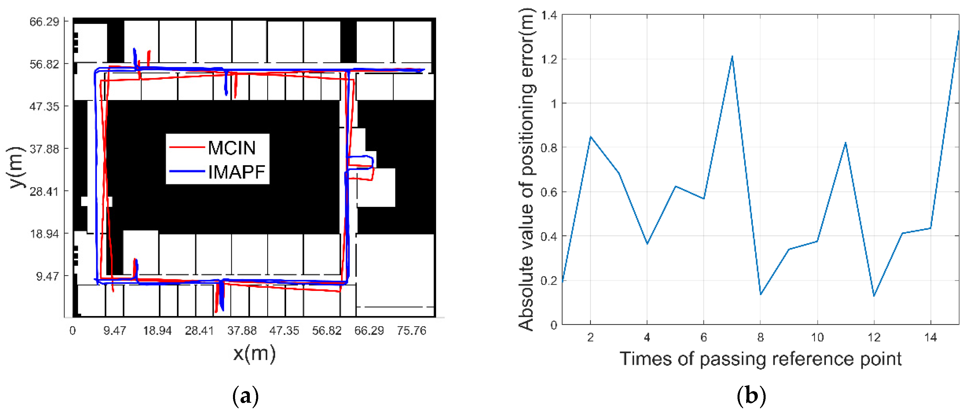
In this paper, the step length and heading change are calculated with the method of multiple constraints for indoor navigation (MCIN) [30] based on multiple constraints, as the input of the IMAPF method proposed in this paper. This method consists of the following two parts: (a) A pedestrian navigation model based on ZUPT is constructed; (b) based on the feature that the difference between heading change of foot and heading change of waist is small in one step motion, a navigation correction model based on the consistency constraint of heading change of waist during human motion is constructed as a virtual observation. This method corrects the pedestrian navigation error in a period of time, but the error will increase when moving for a long time. As the motion state of adjacent steps does not change much in the motion process, the distance between the adjacent zero velocity intervals can be used as the step length control value through the MCIN method. In addition, since the waist IMU motion is relatively stable, the heading change obtained from the waist angular velocity integral is taken as the control value.
The step length is calculated as follows:
l = g k g k 1 2 + h k h k 1 2
In Equation (3), g k , h k and g k 1 , h k 1 are the position coordinates of the current step and the previous step calculated by the MCIN method, respectively.
(2)
Observation model based on particle “not going through the wall” method
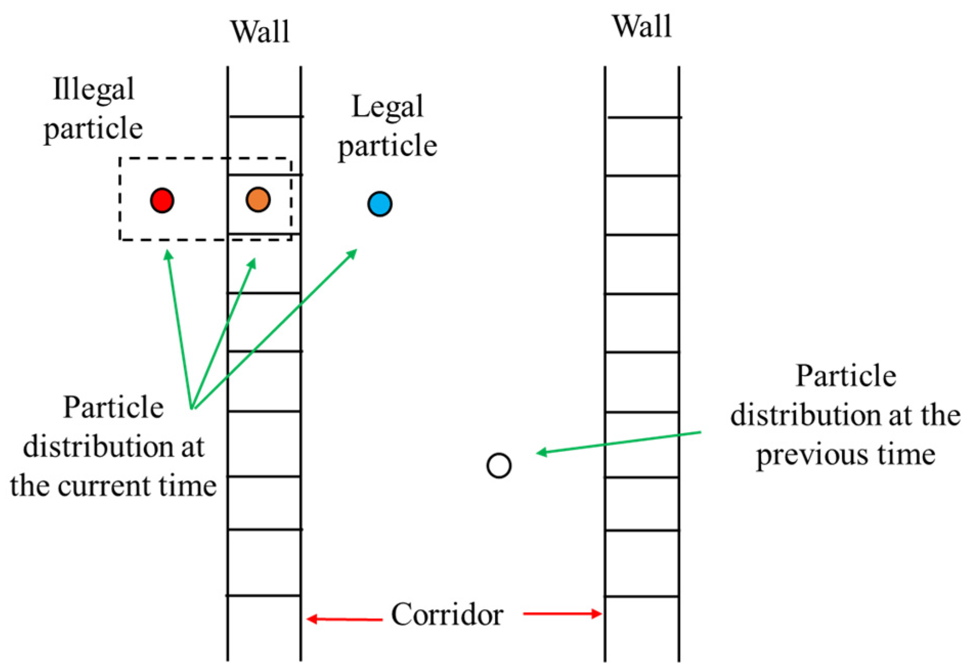
In the navigation and positioning method based on the IMAPF, the “not going through the wall” method is to judge whether the current particle position is valid according to the position of the particle at the previous time after one step of movement.
To determine whether a particle is a “valid particle”, it is based on inaccessible areas in the map (such as patios, elevators, walls, etc.) or impossible paths in reality (such as going from one room to another without going through a door). Figure 3 is a schematic diagram of particle motion. The particles representing the human at the last moment is marked as a white circle, and he is currently walking in the corridor.
According to the state equation, the particle coordinates at the current time can be obtained, including the following possible positions: Corridor, inside the wall, going through the wall into another room, etc. It is compared with the indoor accessible area (the accessible area is obtained through the architectural plan). If a particle position coordinate P k i belongs to the accessible region P e of the blue circle, it is regarded as “legal particle”, and the particle weight w k i will not be changed. When a particle turns into an orange circle through state transition and enters the inaccessible area P m 1 such as the wall, it can be judged that this type of particle is an “illegal particle”, and then the weight value of this type of particle is set to 0. If a particle turns into a red circle and directly enters another room after the state transfer, there is no connectivity between the new particle and the particle at the previous moment, which belongs to an inaccessible area P m 2 . The particle weight value is set to 0, and the “illegal particle” is deleted. The equation is as follows:
w k i = 1 P k i P e 0 P k i P m 1 0 P k i P m 2
The thickness of the wall is determined by the pixel length of the wall after the architectural plan is converted to the binary map. Generally, the physical length represented by one pixel is less than the thickness of the wall, that is, the wall is represented by at least several consecutive pixels. Even when the wall has only one pixel, it is possible to calculate that the particle is inside or through the wall, and then proceed to the next steps. Therefore, the accuracy of the method is independent of the thickness of the wall.

2.2.2. Algorithm Process Design

(1)
Optimization of initial position and heading of particle set
The core idea of PF is that it is composed of a finite number of random samples (particles) with weight. Each particle represents the estimation of the current state. The integral operation of the posterior probability density distribution p x k | y 1 : k 1 is approximately expressed as the sum operation of the finite samples. The posterior probability distribution of the system is expressed by the density of the particle distribution. The value of the particle weight w represents the possibility of the state, which is used to represent the probability distribution of the state variable to approximate the true probability distribution of the system. Select n particles x k i , w k i i = 1 , 2 , , n , with
p x 0 : k | y 1 : k i = 0 N w ˜ k i δ x 0 : k x 0 : k i
i = 0 N w ˜ k i = 1
In Equations (5) and (6), N represents the number of particles, i represents the number of each particle, δ represents the Dirac function, x 0 : k represents the historical system state in time interval 0 ~ k , the observation quantity of the system is marked as y , representing the probability distribution, y 1 : k represents the historical observation in time interval 1 ~ k , and w ˜ k i represents the normalized importance weight of the i th particle at moment k .
At the initial moment, set k = 0 , and randomly generate N sample particle groups { x 0 i , i = 1 , 2 , , N } according to a priori probability p x 0 . The weights of all particles are w 0 i = 1 / N , and each particle sampled is recorded as { x k i , 1 / N } .
The current research mainly focuses on the of navigation and positioning methods for indoor pedestrians when the initial positions and heading are known in a special working environment. The initial particles are added with Gaussian white noise, as shown in Equation (2), and the initial particles obey
p x 0 N μ , σ
In Equation (7), p x 0 is the prior distribution of the initial position, N μ , σ is the Gaussian distribution, μ is the expectation, and σ is the mean square error.
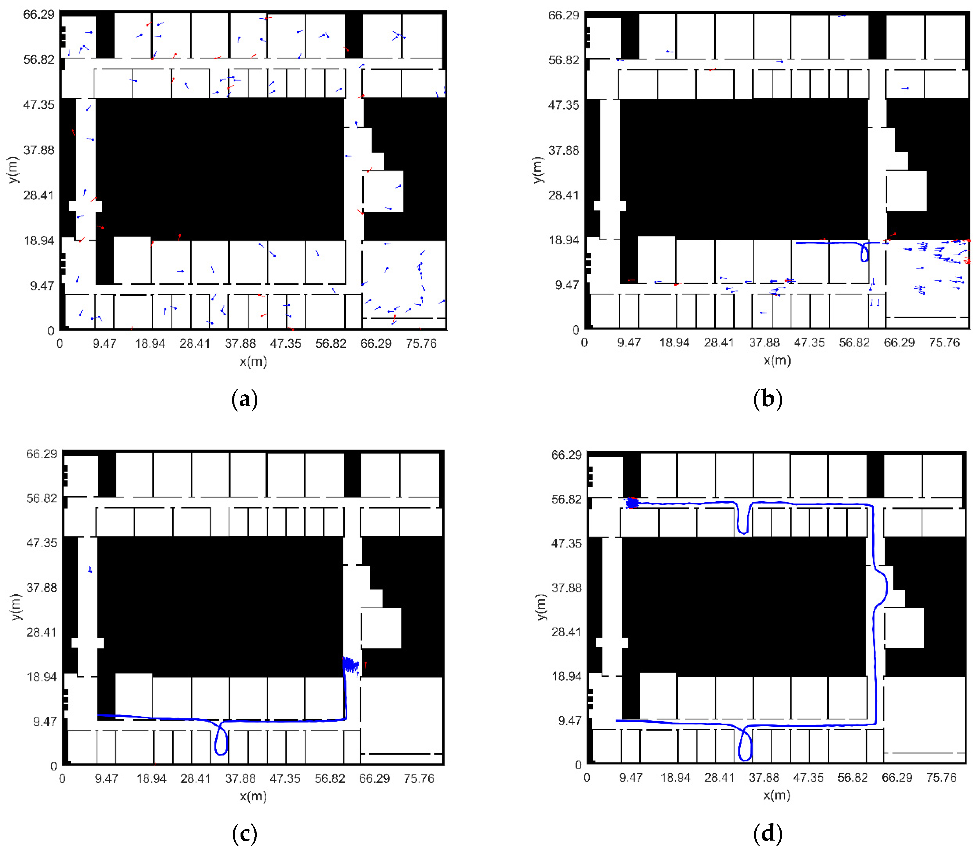
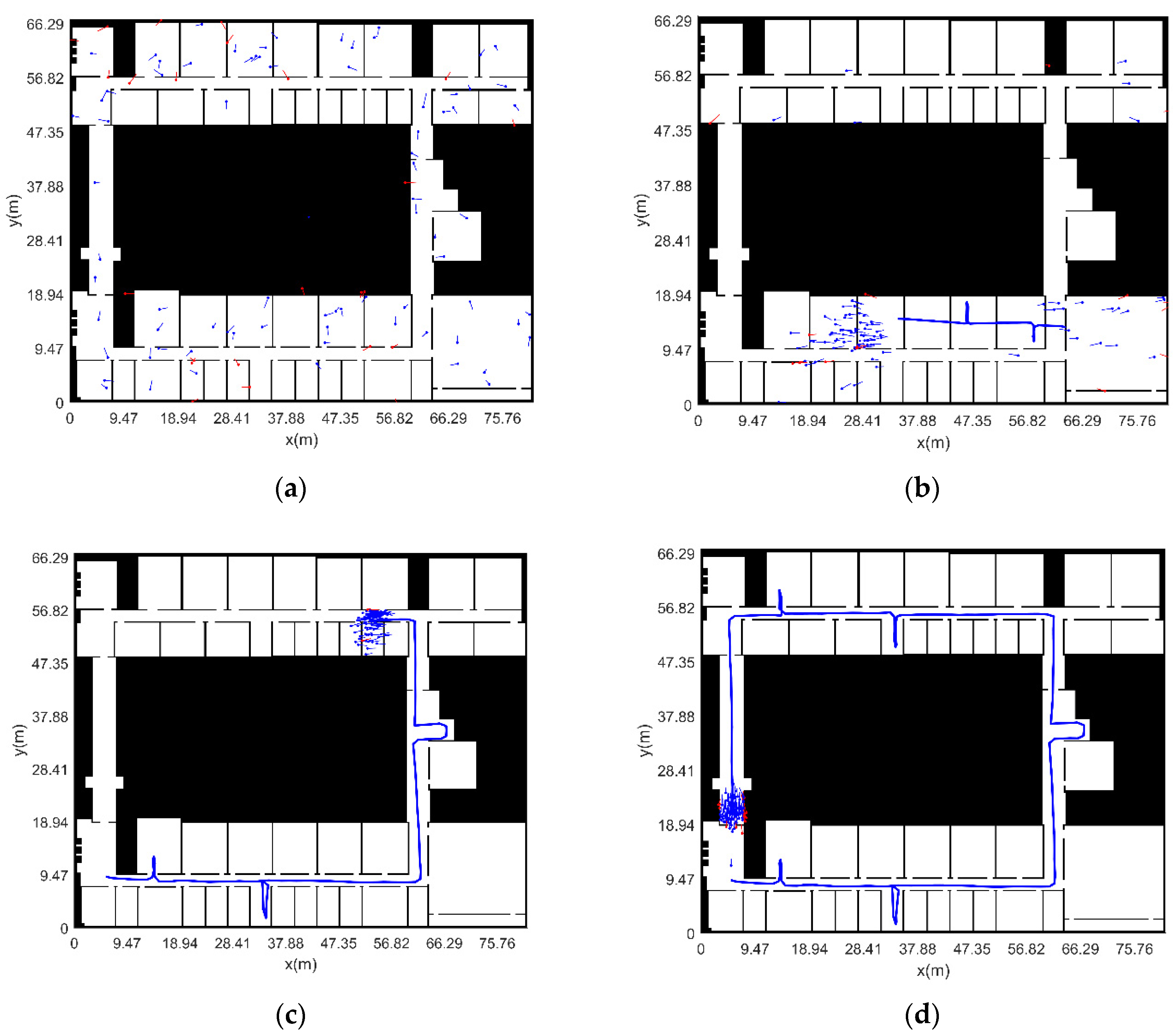
However, in the actual environment, due to the special emergency of the work site and the inability to provide the absolute position information in a short time, when pedestrians must enter the work environment, this paper proposes a method based on global search to solve the pedestrian’s position and heading information. The initial particles are distributed in the entire indoor map in a uniform way, and the following equation holds:
p x 0 U a , b
In Equation (8), p x 0 is the prior distribution of the initial position, U a , b is the uniform distribution, and a and b are the minimum and maximum values of the pixel coordinates in the picture, respectively.
(2)
One-step prediction of particle states
According to the state equation, state x k at the current moment is estimated by the prior probability density of state x k 1 at the previous moment. The prior distribution p x 0 of the initial state is known.
p x k | y 1 : k 1 = p x k , x k 1 | y 1 : k 1 d x k 1 = p x k | x k 1 , y 1 : k 1 p x k 1 | y 1 : k 1 d x k 1 = p x k | x k 1 p x k 1 | y 1 : k 1 d x k 1
(3)
Particle weight updating based on prior map information
Using the observation y k at the current moment, modify p x k | y 1 : k 1 to obtain a posterior probability density p x k | y 1 : k .
p x k | y 1 : k = p y k | x k , y 1 : k 1 p x k | y 1 : k 1 p y k | y 1 : k 1        = p y k | x k p x k | y 1 : k 1 p y k | y 1 : k 1        = p y k | x k p x k | y 1 : k 1 p y k | x k p x k | y 1 : k 1 d x k
At moment k + 1 , y k + 1 is updated, and the importance weight value of the whole state sequence needs to be recalculated, so the amount of calculation increases greatly over time. This problem is solved through Sequential Importance Sampling (SIS). A group of known random samples with weights is used to represent the posterior probability density, and the state estimation value is calculated based on the known random samples and weights.
The prior probability is selected as the importance density function, as follows
q ( x k i | x k 1 i , y k ) = p ( x k i | x k 1 i )
The particles sampled according to this function are as follows:
x k i = q x k | x k 1 , y 1 : k
The normalized importance weight is
w k i = w k 1 i p y k | x k i p x k i | x k 1 i q x k i | x k 1 i , y k
Substituting Equation (11) into Equation (13) has
w k i = w k 1 i p y k | x k i
In Equation (14), p y k | x k i represents the detection result of the particle “not going through the wall” method.
The normalized weight calculation equation is
w ˜ k i = w k 1 i j = 1 N w k i
(4)
Particle resampling based on adaptive particle number
In order to reduce the amount of calculation and avoid unnecessary resampling, judge whether resampling is required according to the effective particle number N e f f . The equation for calculating the effective value of particles is
N e f f = 1 / i = 1 N w k i 2
The smaller the number of effective particles is, the more serious the particle weight degradation is, and the there is more need to resample. Set the resampling threshold N t h , when N e f f N t h , particle set { x k i , w k i } needs resampling.
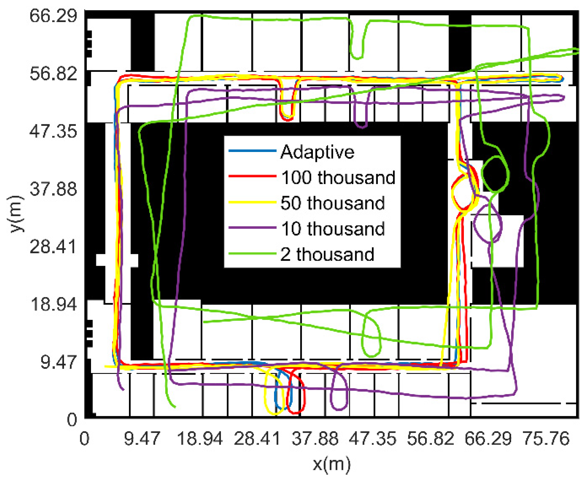
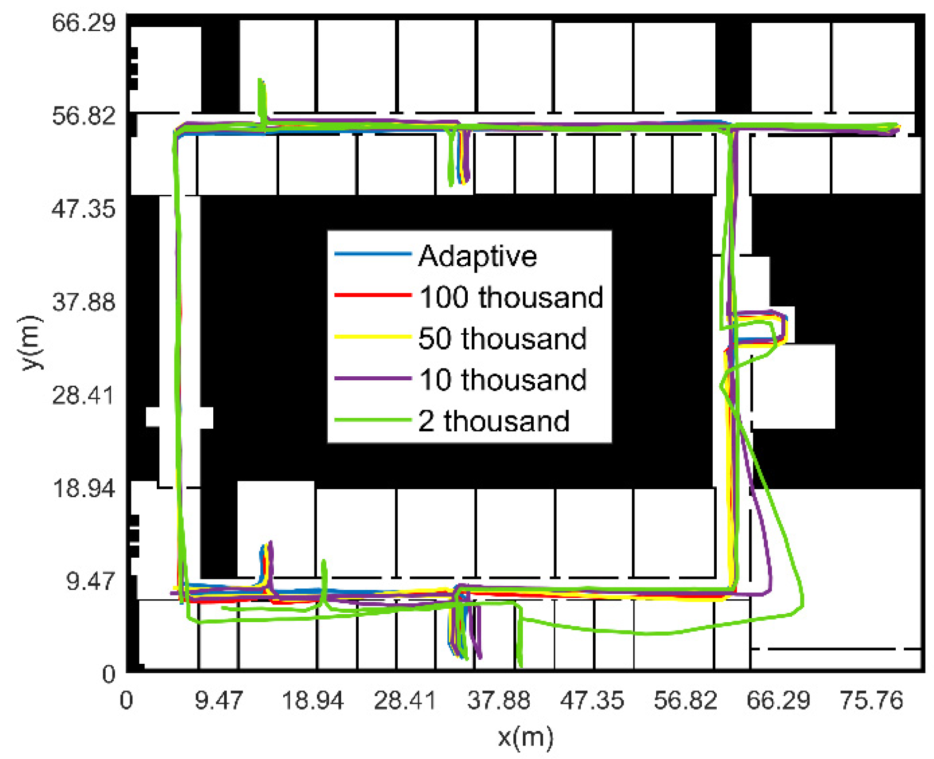
Theoretically, the larger the number of particles, the more accurate the results of PF. However, as the number of particles increases, the calculation time increases exponentially, and the improvement of navigation and positioning accuracy is not obvious, especially for the navigation and positioning results under the condition of the known initial position and heading. For position under the condition of unknown initial position and heading, a large number of particles are required at the beginning. Using a large number of particles after finding the location of a pedestrian in the map will lead to computational inefficiency. Therefore, this paper proposes a method to adaptively adjust the particle number during resampling, which can greatly improve the computational efficiency of PF and ensure the high-precision navigation and positioning results of pedestrian navigation system. The calculation equation of the adaptive particle number is
p N u m = f l o o r ( e c 1 ) + c 2
In Equation (17), f l o o r is the integral function, and e is the sum of the main diagonal elements of the covariance matrix of the position coordinates of all particles at the current moment. c 1 and c 2 are empirical constants. c 1 is the proportional coefficient, and the value of c 2 ensures that the particle filter function can be achieved when p N u m is at the minimum value. In this paper, c 1 and c 2 are 1000 and 2000, respectively.
The updated particle set is recorded as { x k i , 1 / p N u m } .

2.2.3. Algorithm Flow

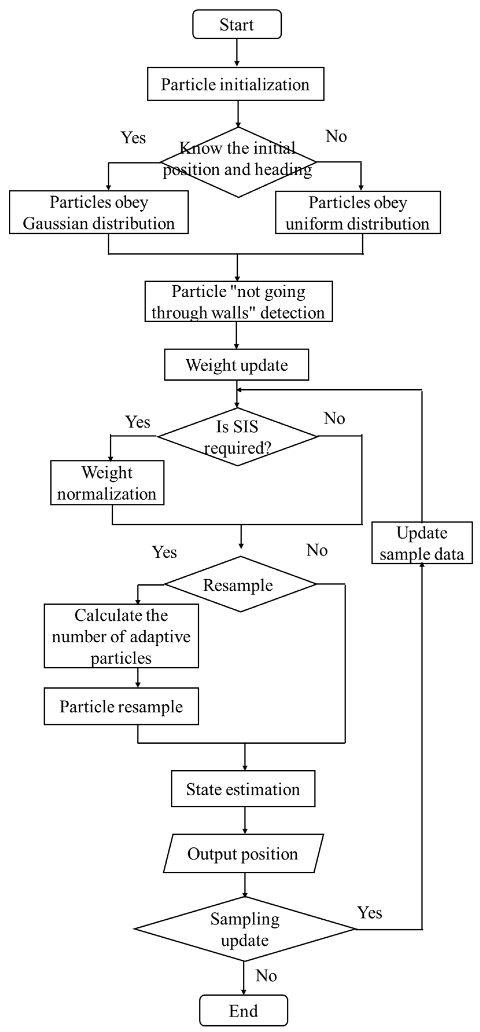
To sum up, the flow chart of pedestrian navigation and positioning method of IMAPF is shown in Figure 4.
The algorithm flow is as follows:
Step 1: Initialization of position and heading of particle set: For the known initial position and heading, the initialization adopts Equation (7) to satisfy the Gaussian distribution. In the case of the unknown initial position and heading, the initialization adopts Equation (8) to meet the uniform distribution.
Step 2: Sequential importance sampling based on particle “not going through the wall” method: Update the particle weight according to the particle “not going through the wall” method, and then calculate the normalized weight value through the Equations (11)–(15).
Step 3: Particle resampling based on adaptive particle number: The particle number is adaptively calculated by Equations (16) and (17) and resample.
Step 4: State estimation and location update: The state x ^ k at the current moment is estimated by the updated adaptive number of particle sets and weights as
x ^ k = i = 1 N w ˜ k i x k i
The position P k at the current moment is
P k = i = 1 N w ˜ k i x k i x ^ k x k i x ^ k T
At moment k, when a particle is in an inaccessible area, the particle is resampled. Copy the navigation parameters (step length and heading at all times of 0~k) of the valid particle to the particle. The weighted average method is used to calculate the position of the pedestrian at the moment k , k 1 , ……, 0 in turn.
Project the updated position onto the indoor map.
Step 5: k = k + 1 , go to Step 2.

3. Results

3.1. Verification of Simulation

3.1.1. Conditions of Simulation

In order to verify the effectiveness of the improved pedestrian navigation and location method based on the indoor map assistance and particle filter, a series of simulation experiments were carried out. The simulation data is processed on the desktop computer, and the computer platform parameters are shown in Table 1.
The simulation environment is based on the architectural plan of the fifth floor of no. 1 Building and no. 2 Building of the College of Automation Engineering, as shown in Figure 5. In Figure 5a, the red line indicates the corridor path. The four black dots (①②③④) represent the reference point of the relative position.
The simulation movement trace is shown in Figure 6a. The blue point at the lower left corner is the starting point/end point. A complete closed loop path ①① has a distance of 207.72 m. The simulation moves two circles in a counterclockwise direction. The parameters are set as follows: The mean square error of the step noise is 0.1 m, and the mean square error of heading change noise is 1°. The simulation data of pedestrian position and course change obtained are also saved. The four reference coordinates in the trace are shown in Figure 6b. Due to the process of entering the room, the total distance cannot be measured accurately, and the total distance exceeds 415.44 m.
Define the positioning error as
E r r = Δ x 2 + Δ y 2
In Equation (20), E r r is the Euclidean Distance between the reference point and the measuring point. Δ x is the difference between the abscissa calculated by the proposed method and the abscissa calculated by the standard path; Δ y is the difference between the ordinate calculated by the proposed method and the ordinate calculated by the standard path.

3.1.2. Analysis of Simulation Results

This section first analyzes the error comparison results between the IMAPF method and the PDR algorithm when the initial position and heading are known, then analyzes the positioning effect of the proposed method and PDR algorithm when the initial position and heading are unknown, and finally analyzes the navigation error and calculation efficiency when the initial position and heading are unknown and the adaptive particle number and fixed particle number.
(1)
The initial position and heading of pedestrian are known
The distribution of the sampled particles is shown in Figure 7. The noise of step length and heading change of particles conform to Gaussian distribution. At the beginning, the particles are distributed within a certain range, with red representing “illegal particles” and blue representing passable “legal particles”.
Figure 8 shows the navigation trace comparison and its positioning error CDF curve with an known initial position and heading. In Figure 8a, the red line represents the ideal trace without noise, the green line represents the trace with noise calculated by PDR, and the blue line represents the trace diagram of the IMAPF method proposed in this paper. It can be seen that the method proposed in this paper can well correct the position of the navigation system. Figure 8b shows the CDF curve, which shows that the algorithm proposed in this paper is better than the PDR method in error correction. Figure 8c shows the error of each step.
Table 2 shows the error comparison under the condition that the initial position and heading are known. It can be seen from the data in the table that the error of PDR algorithm increases with the increase in motion time. The method proposed in this paper can effectively restrain error divergence.
(2)
The initial position and heading of pedestrian are unknown (adaptive particle number)
The distribution of sampling particles is shown in Figure 9. Using the global search method, the particles are evenly distributed in the whole map at the beginning, with red indicating “illegal particles” and blue indicating passable “legal particles”. With continuous movement, the approximate position of pedestrians can be found at the 74th step, and then the positioning coordinates will be modified for pedestrians, finally providing navigation and positioning functions for pedestrians. Due to the structural features, such as rooms and corridors, the path complexity can be increased by increasing the number of room entry and exit to achieve global search as soon as possible.
Figure 10 shows the navigation trace comparison and its positioning error CDF curve under the condition of unknown initial position and heading, while the PDR algorithm is not applicable to this condition. In Figure 10a, the red line represents the real motion trace without noise, and the blue line represents the trace diagram of the IMAPF method proposed in this paper. It can be seen that the method proposed in this paper can provide accurate positioning function for pedestrians when the initial position and heading are unknown. Figure 10b shows the CDF curve, which clearly shows that the algorithm proposed in this paper can provide accurate positioning function for pedestrians under the condition of unknown initial positon and heading. Figure 10c shows the error of each step. The average error of IMAPF algorithm is 0.36 m, and the maximum error is 0.84 m.
It can be seen that the IMAPF algorithm studied in this paper performs better than the PDR algorithm for pedestrian navigation, whether the initial position and heading are known or not.
(3)
The initial position and heading of pedestrian are unknown (fixed particle number)
In order to compare the calculation efficiency and error value between the fixed particle number and the adaptive particle number, under the condition of unknown initial position and heading of pedestrians, the fixed particle number of 2000, 10,000, 50,000 and 100,000 are compared, respectively. Table 3 shows statistics of positioning errors with different particle numbers.
Figure 11 shows the pedestrian motion trajectory obtained by solving with different particle numbers and compares the navigation results of four different particle numbers. The navigation and positioning error value of the adaptive particle number method proposed in this paper is smaller than that of the fixed particle number of 100,000. However, the calculation time of the adaptive particle number method is reduced by about 20 times lower compared to the calculation time of 100,000 fixed particles.

3.2. Experiment and Verification

3.2.1. Experimental Conditions

In order to further verify the practicability and effectiveness of the proposed method, this paper verifies its effect through experiments. In the experiment, five IMUs are used to collect pedestrian movement data, of which four IMUs use FSS-IMU6132 independently designed by Forsense Technology Company to collect accelerometer and gyroscope data with a sampling frequency of 100 Hz; One MTI-G-710 inertial device of XSENS Company is used to collect air pressure data with a sampling frequency of 50 hz. The above five sensors are all connected to Raspberry Pie 4B through data lines, and the mobile phone app controls Raspberry Pie to collect data through Bluetooth communication. The sensor installation method is shown in Figure 12.
The performance parameters of FSS-IMU6132 are shown in Table 4.
The performance parameters of MTI-G-710 are shown in Table 5 below.
The computer performance parameters are shown in Table 1.

3.2.2. Experimental Verification Analysis

(1)
MCIN method
The experimental site is the fifth floor of No.1 Building and No.2 Building of the College of Automation Engineering. The experimental trace and indoor experimental scene are shown in Figure 13. The experimenter started from position ① (0, 0) and walked counterclockwise to collect two rounds of data. The experimenter experiences the reference point in the order of ①②③④⑤⑥⑦⑧①③④⑤⑨⑦⑧①. Additionally, the trace included multiple “entering the house” behaviors. The actual movement time in the experiment is 451.74 s.
The trace solved by the MCIN method and the positioning error of the reference point experienced 15 times are shown in Figure 14. The mean error of the reference point position is 1.98 m, and the maximum error is 4.16 m. For Figure 14b, if the MCIN method based on inertial navigation only is adopted, the navigation error will gradually diverge. Due to the uncertainty of course error divergence, the navigation solution results of some paths in a closed path will show smaller errors.
(2)
The initial position and heading of pedestrian are known
The distribution of sampled particle is shown in Figure 15. The step length and heading change of the particles obey the Gaussian distribution. Initially, the particles are distributed in the range near the starting point, where red represents “illegal particles” and blue represents passable “legal particles”.
Figure 16 shows the motion trace and positioning error under the condition that the initial position and heading are known. In Figure 16a, the red line represents the motion trace solved by the MCIN method, and the blue line represents the trace with IMAPF method. It can be seen that the IMAPF can well correct the position of the navigation system over time. Figure 16b is the absolute value curve of the positioning error under the condition of known initial position and heading, which clearly shows the effectiveness of the algorithm in correcting the error. The MCIN method can effectively restrain error divergence.
Table 6 shows the error comparison under the condition that the initial position and heading are known. It can be seen from the data in the table that the method proposed in this paper can effectively restrain error divergence compared to the MCIN method.
(3)
The initial position and heading of pedestrian are unknown (adaptive particle number)
The distribution of sampled particles is shown in Figure 17. Initially, particles are uniformly distributed throughout the map, with red representing “illegal particles” and blue representing passable “legal particles”. Starting from the 114th step, the general location of the pedestrian is searched. With the continuous movement of the pedestrian, the navigation and positioning function is finally provided for the pedestrian. There is a possibility of symmetry in the indoor structure, and pedestrians may not know in advance. According to the structural characteristics of indoor rooms, corridors, etc., the global search can be realized as soon as possible by increasing the path complexity.
Figure 18 is the comparison diagram of positioning trace under the condition of unknown initial position and heading. In Figure 18a, the red line represents the trace of the MCIN method, and the blue line represents the trace of IMAPF method. It can be seen that with the increase of time, IMAPF method can well correct the position of the navigation system. Figure 18b shows the absolute value curve of the positioning error under the condition that the initial position and heading are unknown. As the pedestrian keeps moving, navigation and positioning functions are gradually provided with map constraints. After 114 steps, functions of navigation and positioning can be provided for pedestrians in the map. Figure 18b shows the absolute value of the positioning error calculated according to the final navigation and positioning results, so the errors of the first two reference points are not considered. It can be seen that the algorithm is effective in correcting errors, which can be limited in a certain range and do not diverge over time. The mean error of IMAPF method is 1.06 m, and the maximum error is 1.33 m.
Figure 16b and Figure 18b show the absolute value of navigation error using the IMAPF method in this paper. In general, the navigation error of IMAPF method is constrained in a small range, which is better than MCIN.
It can be seen that the IMAPF method studied in this paper performs better than the MCIN method for pedestrian navigation, whether the initial position and heading are known or not.
(4)
The initial position and heading of pedestrian are unknown (fixed particle number)
In order to compare the computational efficiency and error value between the fixed particle number and the adaptive particle number, under the condition of unknown pedestrian initial position and heading, the fixed number of particles is 2000, 10,000, 50,000 and 100,000, respectively. Table 7 is the error statistics table of different particle numbers.
Figure 19 shows the pedestrian motion trace obtained by different particle numbers. Comparing the navigation results of five different particle numbers, the adaptive particle number method proposed in this paper is close to the navigation positioning error value when the fixed number of particles is 50,000. The error is small when the number of fixed particles is smaller, but the calculation time of the adaptive particle number method is reduced about 4.7 times lower compared to the calculation time of 50,000 fixed particles.

4. Discussion

The purpose of this paper is to study an improved pedestrian navigation and location method based on the combination of indoor map assistance and adaptive particle filter. For the multi constraint integrated navigation method that only relies on the wearable inertial sensor node network for indoor pedestrians, there is an unavoidable problem of the accumulation and divergence of navigation errors. It is urgent to further improve the accuracy of the navigation system based on the available indoor auxiliary information. Considering that the indoor architectural plan is the most basic and accessible information source in the indoor rescue process, a navigation and positioning method based on the combination of indoor map assistance and particle filter is proposed. This method makes full use of the existing indoor map constraint information to assist in improving the performance of the pedestrian navigation and positioning system based on inertial sensor network. In this paper, the algorithm framework of indoor pedestrian navigation based on map assistance is designed. Combined with the characteristics that pedestrians cannot actually go through the walls and other obstacles when moving in buildings. By establishing the filtering algorithm under the property of particle “not going through the wall”, the effective constraints on navigation error are realized; In view of the pedestrian’s initial entry into an unfamiliar indoor environment, a map aided localization algorithm based on global search is proposed under the condition of unknown initial position and heading; In order to solve the problem that a large number of particles are required to complete the global search, which leads to low computational efficiency, a particle resampling method based on adaptive particle number is proposed. While maintaining the accuracy of navigation and positioning, it also improves the computing efficiency and achieves accurate indoor positioning in unfamiliar environments. On this basis, based on indoor map constraints, the problem of inertial accumulation error divergence is well suppressed, which provides a strong support for pedestrian indoor navigation and positioning with high precision and reliability.
Through the verification and analysis of simulation data and measured data, the pedestrian navigation and positioning method based on the combination of improved indoor map assistance and adaptive particle filter proposed in this paper is suitable for the conditions of known and unknown initial position and heading. In the indoor environment of about 2600 m2, when the total distance exceeds 415.44 m, the mean error and the maximum error of the position relative to the reference point are both less than 2 m. It effectively suppresses the pedestrian navigation error based on inertial devices, and greatly improves the calculation efficiency, which can meet the needs of indoor pedestrians for a long time.
In fact, in the process of motion, both lateral and longitudinal errors are derived from step length error and heading errors. In a one-step correction process, if it is calculated that the coordinates of a particle in the lateral or longitudinal direction are in the inaccessible area, the particle is in the inaccessible area and needs to be resampled and given new navigation parameters. The pedestrian position is then calculated by the weighted average method.
The method proposed in this paper also has some limitations. It is based on the indoor building plan, and combines the characteristics of particles “not going through the wall” to constrain and modify the pedestrian trace. When the indoor structure is simple and the environment is open, then the distance between the walls on both sides of the walkway is very far, it is difficult to correct the pedestrian trace through this method.

5. Conclusions

In this paper, an improved pedestrian navigation method based on indoor map assistance and particle filter is proposed. Based on the fact that particles cannot “going through the wall”, this method limits the pedestrian navigation positioning error to a low range for a long time. In addition, a global search algorithm is proposed to solve the problem of high-precision localization of pedestrians in unfamiliar environments with unknown initial position and heading; An adaptive particle number calculation method in the process of particle resampling is also proposed, which can improve the calculation efficiency and achieve long-term high-precision navigation and positioning for indoor pedestrians.
The method proposed in this paper can be used in indoor environments such as disaster relief and rescue, medical search and rescue. With the building plan and inertial sensors, navigation and positioning accuracy can be maintained for a long time. This method is of great significance to the practical application of pedestrian inertial navigation.
In the future, we will further study the method of multi person cooperative navigation in a complex environment according to the method in this paper to obtain higher navigation and positioning accuracy in a longer period.

Author Contributions

Conceptualization, Z.W., L.X. and Z.X.; methodology, Z.W.; validation, Z.W., Y.D., Y.S. and C.S.; formal analysis, Z.W.; software, Z.W.; data curation, Y.D. and Y.S.; supervision, L.X. and Z.X., writing—original draft, Z.W., L.X. and Z.X.; writing—review and editing, Z.W., L.X., Z.X., Y.D., Y.S. and C.S. All authors have read and agreed to the published version of the manuscript.

Funding

This research was funded by the National Natural Science Foundation of China, grant number 61873125; The National Natural Science Foundation of China, grant number 62073163; The National Natural Science Foundation of China, grant number 62103285; Support for projects in special zones for national defense science and technology innovation; The advanced research project of the equipment development grant number 30102080101; National Basic Research Program, grant number JCKY2020605C009; The Natural Science Fund of Jiangsu Province, grant number BK20181291; The Aeronautic Science Foundation of China, grant number ASFC-2020Z071052001; The Aeronautic Science Foundation of China, grant number 202055052003; The Fundamental Research Funds for the Central Universities, grant number NZ2020004; Shanghai Aerospace Science and Technology Innovation Fund, grant number SAST2019-085; Introduction plan of high end experts, grant number G20200010142. Foundation of Key Laboratory of Navigation, Guidance and Health-Management Technologies of Advanced Aerocraft (Nanjing Univ. of Aeronautics and Astronautics), Ministry of Industry and Information Technology, Jiangsu Key Laboratory “Internet of Things and Control Technologies” & the Priority Academic Program Development of Jiangsu Higher Education Institutions, Science and Technology on Avionics Integration Laboratory. Supported by the 111 Project, grant number B20007.

Data Availability Statement

The study did not report any data. I choose to exclude this statement.

Conflicts of Interest

The authors declare no conflict of interest.

References

  1. Jwo, D.J.; Lee, J.T. Kernel Entropy Based Extended Kalman Filter for GPS Navigation Processing. Comput. Mater. Contin. 2021, 68, 857–876. [Google Scholar]
  2. Cao, X.; Shen, F.; Zhang, S.; Li, J. Time delay bias between the second and third generation of BeiDou Navigation Satellite System and its effect on precise point positioning. Measurement 2021, 168, 108346. [Google Scholar] [CrossRef]
  3. Kröll, H.; Steiner, C. Indoor ultra-wideband location fingerprinting. In Proceedings of the 2010 International Conference on Indoor Positioning and Indoor Navigation, Zurich, Switzerland, 15–17 September 2010. [Google Scholar]
  4. Li, Y.; Zhuang, Y.; Zhang, P.; Lan, H.; Niu, X.; Naser, E.-S. An improved inertial/wifi/magnetic fusion structure for indoor navigation. Inf. Fusion 2017, 34, 101–119. [Google Scholar]
  5. Kriz, P.; Maly, F.; Kozel, T. Improving Indoor Localization Using Bluetooth Low Energy Beacons. Mob. Inf. Syst. 2016, 2016 Pt 2, 1–11. [Google Scholar] [CrossRef] [Green Version]
  6. Bianchi, V.; Ciampolini, P.; De Munari, I. RSSI-Based Indoor Localization and Identification for ZigBee Wireless Sensor Networks in Smart Homes. IEEE Trans. Instrum. Meas. 2019, 68, 566–575. [Google Scholar] [CrossRef]
  7. Chawla, K.; Thomason, W.; Mcfarland, C.; Robins, G. An accurate real-time RFID-based location system. Int. J. Radio Freq. Identif. Technol. Appl. 2018, 5, 48–76. [Google Scholar] [CrossRef]
  8. Nadarajah, V.R.; Singh, M.M. Privacy-by-Design(PbD) IoT Framework: A Case of Location Privacy Mitigation Strategies for Near Field Communication (NFC) Tag Sensor. Adv. Sci. Technol. Eng. Syst. J. 2017, 2, 134–138. [Google Scholar] [CrossRef] [Green Version]
  9. Tian, D.; Ming, D.; Mao, G.; Lin, Z.; David, L.P. Uplink Performance Analysis of Dense Cellular Networks with LoS and NLoS Transmissions. IEEE Trans. Wirel. Commun. 2017, 16, 2601–2613. [Google Scholar]
  10. Mao, K.J.; Wu, J.B.; Jin, H.B.; Miao, C.Y.; Chen, Q.Z. Indoor localization algorithm for NLOS environment. Acta Electron. Sin. 2016, 44, 1174–1179. [Google Scholar]
  11. Marek, P.; Philippe, G.; Rasmus, A. Mapping forests using an unmanned ground vehicle with 3D LiDAR and graph-SLAM. Comput. Electron. Agric. 2018, 145, 217–225. [Google Scholar]
  12. Liu, J.; Gao, W.; Hu, Z. Bidirectional Trajectory Computation for Odometer-Aided Visual-Inertial SLAM. IEEE Robot. Autom. Lett. 2021, 99, 1670–1677. [Google Scholar] [CrossRef]
  13. Qureshi, U.; Golnaraghi, F. An algorithm for the in-field calibration of a MEMS IMU. IEEE Sens. J. 2017, 17, 7479–7486. [Google Scholar]
  14. Ahmed, D.B.; Diaz, E.M. Loose Coupling of Wearable-Based INSs with Automatic Heading Evaluation. Sensors 2017, 17, 2534. [Google Scholar] [CrossRef] [PubMed] [Green Version]
  15. Xu, L.; Xiong, Z.; Liu, J.; Wang, Z.; Ding, Y. A Novel Pedestrian Dead Reckoning Algorithm for Multi-Mode Recognition Based on Smartphones. Remote Sens. 2019, 11, 294. [Google Scholar] [CrossRef] [Green Version]
  16. Ding, Y.; Xiong, Z.; Li, W.; Cao, Z.; Wang, Z. Pedestrian Navigation System with Trinal-IMUs for Drastic Motions. Sensors 2020, 20, 5570. [Google Scholar]
  17. Ruppelt, J.; Kronenwett, N.; Scholz, G.; Trommer, G.F. High-precision and robust indoor localization based on foot-mounted inertial sensors. In Proceedings of the 2016 IEEE/ION Position, Location and Navigation Symposium (PLANS), Savannah, GA, USA, 11–14 April 2016; pp. 67–75. [Google Scholar]
  18. Hsu, Y.L.; Wang, J.S.; Chang, C.W. A Wearable Inertial Pedestrian Navigation System with Quaternion-Based Extended Kalman Filter for Pedestrian Localization. IEEE Sens. J. 2017, 17, 3193–3206. [Google Scholar] [CrossRef]
  19. Suresh, R.P.; Sridhar, V.; Pramod, J.; Talasila, V. Zero velocity potential update (ZUPT) as a correction technique. In Proceedings of the 2018 3rd International Conference on Internet of Things: Smart Innovation and Usages (IoT-SIU), Bhimtal, India, 23–24 February 2018; pp. 1–8. [Google Scholar]
  20. Abdallah, A.A.; Jao, C.S.; Kassas, Z.M.; Shkel, A.M. A pedestrian indoor navigation system using deep-learning-aided cellular signals and ZUPT-aided foot-mounted IMUs. IEEE Sens. J. 2021, 22, 5188–5198. [Google Scholar] [CrossRef]
  21. Ilyas, M.; Cho, K.; Baeg, S.-H.; Park, S. Drift reduction in pedestrian navigation system by exploiting motion constraints and magnetic field. Sensors 2016, 16, 1455. [Google Scholar] [CrossRef] [Green Version]
  22. Song, J.W.; Park, C.G. Enhanced pedestrian navigation based on course angle error estimation using cascaded Kalman filters. Sensors 2018, 18, 1281. [Google Scholar] [CrossRef] [Green Version]
  23. Diez, L.E.; Bahillo, A.; Bataineh, S.; Masegosa, A.D.; Perallos, A. Enhancing improved heuristic drift elimination for wrist-worn PDR systems in buildings. In Proceedings of the 2016 IEEE 84th Vehicular Technology Conference (VTC-Fall), Montreal, QC, Canada, 18–21 September 2016; pp. 1–5. [Google Scholar]
  24. Muhammad, M.N.; Salcic, Z.; Wang, K.I.-K. Detecting turns and correcting headings using low-cost INS. J. Navig. 2018, 71, 189–207. [Google Scholar] [CrossRef]
  25. Kim, S.-Y.; Park, Y.-Y.; Lee, K.-O.; Jung, J.-B.; Kye, J.-E. A Study on the Making Indoor Topology Map for the Autonomous Driving of Wearable Robots. Ilkogr. Online 2021, 20, 1153–1159. [Google Scholar]
  26. Angermann, M.; Robertson, P. FootSLAM: Pedestrian Simultaneous Localization and Mapping Without Exteroceptive Sensors—Hitchhiking on human perception and cognition. Proc. IEEE 2012, 100, 1840–1848. [Google Scholar] [CrossRef]
  27. Kaiser, S.; Puyol, M.G.; Robertson, P. Measuring the Uncertainty of Probabilistic Maps Representing Human Motion for Indoor Navigation. Mob. Inf. Syst. 2016, 2016, 9595306. [Google Scholar] [CrossRef]
  28. Wang, Q.; Luo, H.; Men, A.; Zhao, F.; Huang, Y. An Infrastructure-Free Indoor Localization Algorithm for Smartphones. Sensors 2018, 18, 3317. [Google Scholar] [CrossRef] [Green Version]
  29. Yu, C.; El-Sheimy, N.; Lan, H.; Liu, Z. Map-based indoor pedestrian navigation using an auxiliary particle filter. Micromachines 2017, 8, 225. [Google Scholar] [CrossRef] [Green Version]
  30. Wang, Z.; Xiong, Z.; Xing, L.; Ding, Y.; Sun, Y. A method for autonomous multi-motion modes recognition and navigation optimization for indoor pedestrian. Sensors 2022, 22, 5022. [Google Scholar] [CrossRef]
Figure 1. General scheme of the indoor pedestrian navigation and location method based on the IMAPF method.
Remotesensing 14 06282 g001
Figure 2. Schematic diagram of the pedestrian motion trace update.
Remotesensing 14 06282 g002
Figure 3. Schematic diagram of the update of the particle position.
Remotesensing 14 06282 g003
Figure 4. Flow chart of the improved pedestrian navigation and positioning method based on IMAPF.
Remotesensing 14 06282 g004
Figure 5. Digital map on the fifth floor. (a) Architectural plan. (b) Available binary maps.
Remotesensing 14 06282 g005
Figure 6. Simulation trace and coordinates of reference point. (a) Simulation trace. (b) Schematic diagram of the coordinates of the reference point.
Remotesensing 14 06282 g006
Figure 7. Sampling particle distribution and motion trace with known position and heading. (a) Particle distribution at initial moment. (b) Particle distribution in motion.
Remotesensing 14 06282 g007
Figure 8. Navigation trace comparison and positioning error CDF curve with known initial position and heading. (a) Comparison diagram of positioning trace. (b) CDF curve of positioning error. (c) Absolute position error of each step.
Remotesensing 14 06282 g008
Figure 9. Sampling particle distribution and motion trace with unknown initial position and heading. (a) Particle distribution at initial moment; (b) particle distribution and motion trace of the 44th step in the motion process; (c) particle distribution and motion trace of the 74th step in the motion process; and (d) particle distribution and motion trace of the 162th step in the motion process.
Remotesensing 14 06282 g009
Figure 10. Navigation trace comparison and positioning error CDF curve with unknown initial position and heading. (a) Comparison diagram of positioning trace; (b) CDF curve of positioning error; and (c) absolute position error of each step.
Remotesensing 14 06282 g010
Figure 11. Pedestrian motion trace calculated with different particle numbers under simulation conditions.
Remotesensing 14 06282 g011
Figure 12. Schematic diagram of sensor installation. (a) Installation diagram of sensors on waist. (b) Installation diagram of sensors on leg and foot.
Remotesensing 14 06282 g012
Figure 13. Indoor experiment scene and experiment trace. (a) Indoor experiment scene. (b) Reference points.
Remotesensing 14 06282 g013
Figure 14. Two dimensional trace and absolute value of positioning error based on MCIN method. (a) Two dimensional trace. (b) Absolute value of positioning error.
Remotesensing 14 06282 g014
Figure 15. Sampling particle distribution and motion trace under the condition of known initial position and heading. (a) Particle distribution at the initial moment. (b) Particle distribution and trace during motion.
Remotesensing 14 06282 g015
Figure 16. Navigation trace comparison and curve of absolute value of positioning error with known initial position and heading. (a) Positioning trace comparison diagram. (b) Absolute value of positioning error.
Remotesensing 14 06282 g016
Figure 17. Distribution of sampled particles and motion trace with unknown initial position and heading. (a) Particle distribution at initial moment. (b) Particle distribution and motion track of the 58th step in the motion process. (c) Particle distribution and motion track of the 114th step in the motion process. (d) Particle distribution and motion track of the 190th step in the motion process.
Remotesensing 14 06282 g017
Figure 18. Navigation trace comparison and curve of absolute value of positioning error with unknown initial position and heading. (a) Positioning trace comparison diagram. (b) Absolute value of the positioning error.
Remotesensing 14 06282 g018
Figure 19. Pedestrian motion trace calculated with different particle numbers under experimental conditions.
Remotesensing 14 06282 g019
Table 1. Computer platform parameters.
CharacteristicParameter
Computer operating systemWindows10
CPUIntel(R) Core(TM) i7-8700,
Dominant frequency 3.20 GHz
Memory32 GB
SoftwareMatlab2020
Table 2. Error comparison under the condition that the initial position and heading are known.
Navigation MethodMean Error (m)Maximum Error (m)
PDR4.7811.81
IMAPF0.441.18
Table 3. Statistics of positioning errors with different particle numbers under simulation conditions.
Particle NumberMean Error (m)Maximum Error (m)Calculation Time (s)
2 thousand fixed particles10.3415.9916.64
10 thousand fixed particles7.7412.07103.05
50 thousand fixed particles0.753.01909.04
100 thousand fixed particles0.501.912624.36
adaptive particle numbers0.360.84116.14
Table 4. Performance parameters of FSS-IMU6132.
/Sensor RangeBias Stability
Accelerometer ± 6   g 1 0   μ g
Gyroscope ± 500   deg / s 1 . 0   deg / h
Table 5. Performance parameter of XSENS MTI-G-710.
/Sensor RangeTotal Root Mean Square Noise
Barometer 300 1100   mBar 3 . 6   Pa
Table 6. Error comparison under the condition that the initial position and heading are unknown.
Navigation MethodMean Error (m)Maximum Error (m)
MCIN1.984.16
IMAPF0.540.98
Table 7. Statistics of positioning errors with different particle numbers under experimental conditions.
Particle numberMean Error (m)Maximum Error (m)Calculation Time (s)
2 thousand fixed particles3.897.0316.37
10 thousand fixed particles2.749.2193.02
50 thousand fixed particles1.131.40755.33
100 thousand fixed particles1.041.112229.13
adaptive particle number1.061.33131.59
Publisher’s Note: MDPI stays neutral with regard to jurisdictional claims in published maps and institutional affiliations.

