Article

Distributed Satellite Relay Cooperative Communication with Optimized Signal Space Dimension

1
The School of Cyber Engineering, Xidian University, Xi’an 710071, China
2
Information Science Research Center, Xidian University, Xi’an 710071, China
*
Author to whom correspondence should be addressed.
Remote Sens. 2022, 14(18), 4474; https://doi.org/10.3390/rs14184474
Submission received: 10 August 2022 / Revised: 2 September 2022 / Accepted: 4 September 2022 / Published: 8 September 2022

Abstract

:
With the increasingly obvious trend of satellite communication and network integration, especially the emergence of inter satellite links, the interconnection between space nodes has become the development trend and inevitable requirement of future space communication. However, problems, such as long communication distance, large transmission delay and loss, limited network resources and frequent switching of transmission links, limit the ability of spatial information transmission. Firstly, based on the idea of ring planning and design, this paper uses the joint design of beamforming between nodes to design the physical layer network coding in the relay to realize the reliable transmission of information. Secondly, according to the diversity of relay signal space resources and network node information exchange, a joint design method of relay compression matrix and node precoding vector is studied, which breaks through the existing configuration constraints. In this scheme, the computational complexity is reduced by compressing and precoding the matrix to ensure reliable decoding while obtaining spatial alignment gain and degrees of freedom. Simulated and real data results demonstrate the superiority and effectiveness of the proposed method.

Graphical Abstract

1. Introduction

With the development of new high-resolution remote sensors that need to deal with massive amounts of information, requirements for the data transmission rate of new earth observation satellites, data relay satellites and space communication network nodes are becoming higher and higher [1,2,3,4,5]. When remote sensing satellites conduct observations and communications, due to the long transmission distance of electromagnetic waves, it is inevitable that large deep space free space losses will occur due to factors such as space radiation, solar wind and corona. Insufficient observational resources and limited capacity are one of the main factors affecting the acquisition of remote sensing satellite images. In order to improve the image acquisition capability and timeliness of remote sensing satellites, high-orbit satellites are used for data relay to increase spectral efficiency and transmission reliability. At present, there are more and more networked satellite projects either in orbit or planned for launch in the field of remote sensing, and the scale is getting bigger and bigger. In order to meet the fundamental requirements of satellite nodes, it is necessary to build a more intelligent constellation system.
Space-based networks are an important part of intelligent constellations. They have a unique location advantage and can provide continuous service with seamless coverage around the world. Space information transmission based on satellite cooperation has the advantages of long communication distance, large capacity, and flexibility. However, large delay and high bit error rate (BER) make the space information transmission based on satellite cooperation less reliable. This has become the key problem that needs to be solved in space communication. In view of these problems, most of the existing research has used the traditional relay cooperation methods of Amplify and Forward (AF) and Decode and Forward (DF). For near-earth satellite communication networks, [6] selected the relay node whose received signal-to-noise ratio is higher than the set threshold as cooperative relay, and gave the interrupt probability expression and system performance simulation results under AF and DF cooperation modes respectively. Based on DF cooperative satellite communication, [7] adopted the maximum ratio combining (MRC) and selective diversity combining (SDC) methods with the objective of minimizing outage probability. Reference [8], based on AF cooperative satellite communication, transmitted the received source satellite signal to the ground destination node with multiple antennas through beamforming vector amplification. The destination node adopted MRC method to receive signals. The average symbol error rate under different modulation modes and different antenna numbers was simulated and analyzed. Network coding technology was used in the scenario of multi-beam satellite cooperative communication and the minimum transmission time was obtained by comprehensively considering the load per beam and channel conditions [9,10,11]. The results show that the system throughput has been greatly improved after the introduction of network coding.
In the future, the space earth cooperative communication network will include not only satellite nodes in the traditional space segment, but also high-altitude platforms (HAPs), unmanned aerial vehicles (UAVs) and other space nodes in the adjacent space. This is a complex communication network with wide coverage, large capacity, strong time-variances and is multi-level. At present, the existing satellite network topology control strategies can be divided into three categories, the first of which is virtual node policy [12]. The basic idea of this is to use the concept of satellite logical location to form a virtual network covering the whole world. Each node in the network is a virtual node, which is served by the nearest satellite. This strategy regards the satellite network as a fixed topology to shield the movement of satellites. Secondly, there is the coverage division method [13]. The basic idea is to divide the earth’s surface into several cells at equal intervals. Due to the rotation of the earth and the movement of satellites, each satellite adopting this strategy needs to update the topology information of the network. Before transmitting data, the source satellite needs to calculate the corresponding destination satellite according to the geographical coordinates of the destination node. Finally, there is virtual topology policy [14,15,16,17,18]. The basic idea is to divide a system cycle into several time slices with the change of inter satellite link occurring only at the end time point of each time slice. The future space communication network has the inherent characteristics of complex structure, dynamic topology and unstable transmission quality. The first classification of satellite network topology control strategy faces the problems of long delay, high bit error rate and low connectivity of spatial information transmission. A reliable and effective spatial information cooperative transmission and routing scheme should be designed and proposed.
Space interference is one of the main modes of cooperative communication interference among satellite nodes. Space interference mainly includes near-satellite interference and adjacent channel interference. With the rapid development of satellite communication, there are more and more synchronous orbit satellites. Satellite spacing has been reduced from about five degrees to about two and a half degrees now, which will inevitably lead to near satellite interference. The disturbed signal exceeds the coverage of the original signal and is easy to be doped with the signals of its near satellites. This leads to a sharp decline in the performance of the transmission signal [19,20,21,22]. Adjacent channel interference is mainly caused by the overlap between the node carrier frequency allocation and the frequency bands of adjacent signal when there is not enough protection bandwidth. Alternatively, it may happen when the carrier spectrum characteristics of satellite nodes do not meet requirements, resulting in high noise bottom or sidelobe [23,24,25].
With the propagation characteristics of electromagnetic waves, satellite cooperative nodes share limited spectrum resources. Since wireless electromagnetic waves are omnidirectional broadcast transmissions, signals transmitted at the same time in the same frequency band will inevitably produce common channel interference (CCI). Although CCI is not a new concept, the characteristics of CCI in a multiple input multiple output (MIMO) environment are different from those of traditional single input single output (SISO). MIMO not only provides spatial degrees of freedom (DoF), but also greatly increases the difficulty and complexity of anti-jamming algorithms. The reception and demodulation of the satellite cooperative node is essentially to decompose the superimposed signal and design a signal structure that can be encoded at the physical layer. Designing the key method is important to realize cooperative transmission. The interference in the satellite cooperative network has a unified transmission system and a unified performance evaluation system, so it can share resources and cooperate with each other in the physical layer. Using the unique broadcast characteristics of wireless communication and the superposition of signal electromagnetic waves, physical layer network coding can multiply the throughput of wireless relay networks without requiring additional resources. This paper studies the theory and method of interference utilization based on physical layer network coding. The signals of different nodes are superimposed over the air. Self-interference cancellation is performed at the receiving node to improve spectrum utilization. The main contributions of this paper are as follows:
(i)
Joint design of signal spatial structure optimization and superposition signal separation method. Based on the signal space reconstruction model, the cooperative node space compression method is designed to get rid of interference management constraints. The joint design of beam forming of multiple access nodes is realized.
(ii)
Adaptive scheduling of multi-interactive cooperative transmission. The general processing strategy for complex transmission mode and its application in multi-directional relay transmission are studied.

2. Materials and Methods

The intelligent constellation is composed of satellites and inter satellite links, forming a space transmission backbone network. Due to the large scale of satellites, constellation networks often adopt sub constellations with different orbital heights and inclination angles to form multi-layer hybrid constellations. As the access node of space network, satellite plays the role of space-based mobile base station. Microwave inter satellite links can be established between satellites to realize data relay and forwarding. The contact graph routing (CGR) algorithm based on the connection graph model can not only calculate multiple paths at the same time, but also consider the consumption of link bandwidth. It can be used not only in deep space networks, but also in earth orbiting satellite networks. Satellite networks usually adopt dynamic graph model and optimization theory to design and optimize information transmission. With the periodic and predictable orbital motion characteristics, some topology control strategy is generally used in traditional satellite networks to shield the dynamics of topology. Then the static topology sequence is optimized for transmission and routing.
The satellite communication system mainly adopts point-to-point unicast transmission when providing services to another node. However, for the current fast-growing multicast services, this physical layer transmission method is not efficient. Multicast service mainly refers to the service type that needs to send the same information to specific multiple nodes. If the point-to-point physical layer transmission mode is adopted directly, the more wireless resources will be consumed. Satellite has the broadcasting characteristics of wireless communication. For these multicast services, point-to-multipoint multicast transmission can be used in the physical layer to achieve more effective transmission. Facing the huge application demand and more diversified business types in the future, the satellite communication system will face new transmission models, namely multi-channel unicast transmission and multi-channel multicast transmission. Many inter satellite link propagation models can be represented by directed graph which is given in Figure 1. With K satellite communication nodes, a weighted digraph consists of K nodes and at most K(K−1) directed edges. If there is a directed edge from node i to node j and its weight is d i , j , it means that node i sends a message flow with degree of freedom d i , j to node j. If two nodes are not adjacent, it means that no message is transmitted between the two nodes.

2.1. Signal Model

Consider a satellite relay cooperative transmission network with K nodes. Each transmission node is configured with M i , i = 1 , , K antennas, and the relay forwarding node is configured with N antennas. For simplicity of description, it is assumed that each transmission node has the same antennas of M. Because the transmission distance is too long and the energy of the transmitted signal is limited, the nodes use the relay forwarding mode to exchange information [26,27,28]. Node i expects to send message W [ i ] through the cooperative transport network, and at the same time receives and decodes messages that may be transmitted by any other node except its own. { W ^ [ 1 ] , W ^ [ 2 ] , , W ^ [ K ] } / { W ^ [ i ] } .
The entire transmission process is divided into two stages. In the first stage, all nodes that need to transmit messages send signals to the relay simultaneously. This is called multiple access channel (MAC). It is described by
y [ R ] = i = 1 K H [ R , i ] x [ i ] + n [ R ]
where, H [ R , i ] is the channel transmission matrix from node i to relay R, and the size is N × M i . x [ i ] C M i is the signal vector finally transmitted by node i after signal processing. n [ R ] C N represents the white Gaussian noise. The signals transmitted by all nodes satisfy the power constraints E [ T r ( x [ i ] x [ i ] H ) ] S N R . Due to the strong direct component in satellite communication and few scatterers in the channel, the MIMO channel changes slowly. The elements of the channel transmission matrix satisfy the independent and identical distribution under the complex Gaussian random variable, N C ( 0 , 1 ) .
The relay receives and separates the superimposed signal and encodes it into the signal to be sent. The second stage is the broadcast channel (BC) stage, where the relay transmits the encoded signal to all destination nodes in the form of broadcast. The broadcast signal received by node i is as follows:
y [ i ] = H [ i , R ] x [ R ] + n [ i ]
where, H [ i , R ] is the channel transmission matrix from relay R to node i, and the size is M i × N . x [ R ] C N is the signal vector finally transmitted by the relay after signal processing. n [ i ] C M represents the white Gaussian noise. The signals transmitted by the relay satisfy the power constraints E [ T r ( x [ R ] x [ R ] H ) ] S N R .
During the MAC phase, K 1 independent messages W [ j , i ] are sent from node i to the relay for node j where i , j { 1 , 2 , K } and j i . It uses the precoding vector to construct the spatial direction to send the encoded flow. Specifically, it can be expressed as:
x [ i ] = j = 1 , j i K v [ j , i ] s [ j , i ] , i { 1 , 2 , , K }
The network coding technology of signal space alignment is to design the beam space alignment direction, so that the signals sent by the two nodes that exchange information are aligned to the same signal subspace. At the same time, the different alignment directions are kept independent to avoid mutual interference. The relay performs joint detection of decoding and forwarding on the received superimposed signal. The design of the beamforming vector should satisfy:
H [ R , 1 ] v [ 2 , 1 ] = H [ R , 2 ] v [ 1 , 2 ] = u [ R , 1 ] H [ R , 1 ] v [ 3 , 1 ] = H [ R , 3 ] v [ 1 , 3 ] = u [ R , 2 ] H [ R , K 1 ] v [ K , K 1 ] = H [ R , K ] v [ K 1 , K ] = u [ R , K ( K 1 ) 2 ]
The received signal at the relay can be expressed as
y [ R ] = i = 1 K H [ R , i ] x [ i ] + n [ R ] = i = 1 K H [ R , i ] j = 1 , j i K v [ j , i ] s [ j , i ] + n [ R ]
Therefore, the relay received signal can be further expressed as:
y [ R ] = i = 1 K H [ R , i ] j = 1 , j i K v [ j , i ] s [ j , i ] + n [ R ] = [ u [ R , 1 ] , , u [ R , K ( K 1 ) 2 ] ] × [ s [ 2 , 1 ] + s [ 1 , 2 ] s [ 3 , 1 ] + s [ 1 , 3 ] s [ 4 , 1 ] + s [ 1 , 4 ] s [ K , K 1 ] + s [ K 1 , K ] ] + n [ R ] = U [ R ] s [ R ] + n [ R ]
In the BC phase, the relay broadcasts the coded message of the physical layer network at the same time W π ( 1 , 2 ) [ R ] , W π ( 1 , 3 ) [ R ] ,…, W π ( K 1 , K ) [ R ] to other destination nodes by encoded flow s [ 1 , R ] , s [ 2 , R ] ,…, s [ K ( K 1 ) / 2 , R ] with beamforming vectors v [ 1 , R ] , v [ 2 , R ] , …, v [ K ( K 1 ) 2 , R ] , which is denoted as
x [ R ] = i = 1 K ( K 1 ) / 2 v [ i , R ] s [ i , R ]
The receiver uses interference null-space beamforming combined with receive antenna selection (RAS) to suppress undesired interfering signals. Each node utilizes a selection gain to select a portion of the receive antennas for receiving signals. Therefore, the received precoding vector must lie in the intersecting null space of other non-target nodes:
v [ 1 , R ] { n u l l ( H ^ [ 2 , R ] ) n u l l ( H ^ [ 3 , R ] ) n u l l ( H ^ [ 4 , R ] ) n u l l ( H ^ [ K , R ] ) }
where H ^ [ j , R ] is the equivalent transmission channel formed by the antenna selection of the receiving node j, and the matrix size is: ( K 1 ) × M . Beamforming vectors for other nodes can be constructed in the same way.
The received signal of node j is
y ^ [ j ] = H ^ [ j , R ] [ v 1 [ j , R ] , v 2 [ j , R ] , v K ( K 1 ) / 2 [ j , R ] ] [ s [ 1 , R ] s [ 2 , R ] s [ K ( K 1 ) 2 , R ] ] + n ^ [ j ] = Q ^ [ j , R ] s [ R ] + n ^ [ j ]
where Q ^ [ j , R ] represents the equivalent channel of node j after interference suppression. Each node can use zero-forcing decoding to detect the physical layer network coded signal it expects to receive. The self-information is used to realize information reception that eliminates interference.

2.2. Cooperative Transmission of Spatial Information Network

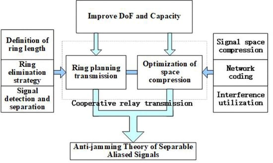
2.2.1. Universal Multicast Transmission Strategy Based on Ring Planning

The existing research results basically focus only on a specific model. However, in reality there are more hybrid transmission models. Due to the change of channel transmission model, the signal receiving model of the whole system changes. Optimization criteria are also different. In practical application scenarios, the channel quality is different due to the different geographical location and path loss of different nodes. In order to maximize the use of channel capacity, communication nodes adaptively choose different code rates and modulation methods according to the channel quality. Thus, an asymmetric transmission channel is formed. Therefore, aiming at the complex communication scenario of asymmetric/symmetric coexistence, a generalized method to systematically solve the heterogeneous information transmission under the condition of multicast is proposed.
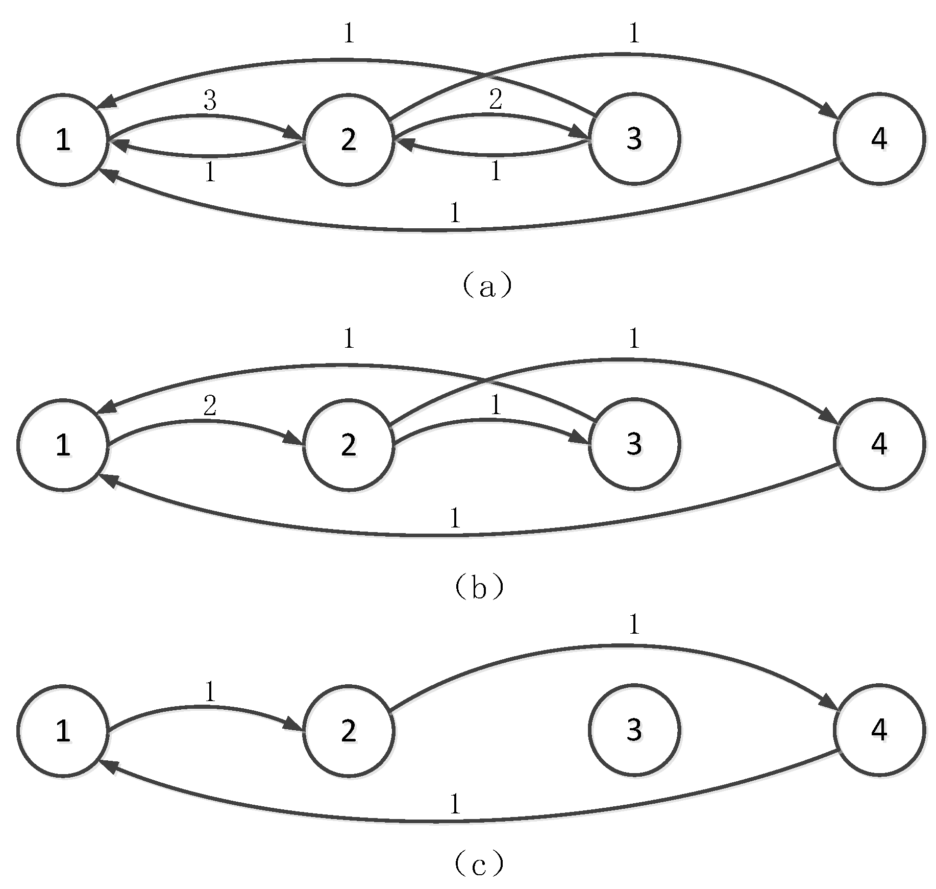
Message transmission is expressed by adjacency of nodes in a weighted directed graph. Each directed edge represents a message flow. The degrees of freedom of the message are represented by the weights of the edges in the directed graph, and the directed edge is omitted when the weight is 0. Take a 4-node multicast channel as an example. Assuming that the number of relay antennas N is 6, DoF is a tuple d = ( 3 , 0 , 0 , 1 , 2 , 1 , 1 , 1 , 0 , 1 , 0 , 0 ) . The information interaction among nodes is shown in Figure 2. If the information exchange occurs at nodes 1 to 2, 2 to 3, and 3 to 1, it is said to constitute a closed loop 1 2 3 1 . For K-node multicast relay channels, there may be a closed loop with length of 2 ( 1 2 1 ) to a closed loop with length of K ( 1 2 K 1 ). As an example, it can be seen in Figure 2a, there is a ring with a length of 2 ( 1 2 1 ) and ( 2 3 2 ). There is a ring of length 3 ( 1 2 3 1 ) and ( 1 2 4 1 ).
One-way transmission: When the one-way strategy is adopted, the relay uses decoding and forwarding to realize the one-way data communication of the point-to-point channel. The transmitted signal occupies a one-dimensional resource of the relay signal space. If this transmission method is used to realize the message transmission with tuple d in DoF, d = d 12 + d 13 + d 14 + d 21 + d 23 + d 24 + d 31 + d 32 + d 34 + d 41 + d 42 + d 43 N must be satisfied. However, since d = 10 > N , the condition d cannot be obtained for one-way transmission at this time.
Two-way transmission: There is a problem with using a bidirectional strategy to solve 2-ring. The one-dimensional signals W [ 1 , 2 ] and W [ 2 , 1 ] interacted by nodes 1 and 2 are aligned to the same signal space of the relay with the signal space alignment (SSA) algorithm. Then, relay can decode to obtain a linear combination of the two signals L ( W [ 1 , 2 ] , W [ 2 , 1 ] ) . After the physical layer network coding, this information is sent to nodes 1 and 2 at the same time in the BC phase. Each node uses the message sent by itself as side information to decode the desired signal.
After 1 2 1 and 2 3 2 transmissions are implemented using the above method, the remainder of the DOF tuples become d = ( d 12 d 21 , 0 , 0 , 0 , d 23 d 32 , d 24 , d 31 , 0 , 0 , d 41 , 0 , 0 ) . If one-way transmission is used to complete the rest of the information interaction, d 12 d 21 + d 23 d 32 + d 24 + d 31 + d 41 dimensional space is required. Synthesize the above two steps to obtain DOF tuple d , which needs to meet d = d 21 + d 12 d 21 + d 32 + d 23 d 32 + d 24 + d 31 + d 41 N . However, due to d = 8 > N , although the use of bidirectional transmission cuts down the two-dimensional signal space requirements, d is still not available.
Multi-ring transmission: DOF tuples d cannot be obtained by using the combination of one-way transmission and two-way transmission. As shown in Figure 2b, when the relay uses two-dimensional space to transmit the bidirectional signals of nodes 1 and 2, 2 and 3, the remaining DOF tuples become d = ( 2 , 0 , 0 , 0 , 1 , 1 , 1 , 0 , 0 , 1 , 0 , 0 ) . Align the signals W [ 1 , 2 ] and W [ 2 , 3 ] sent by node 1 and node 2 respectively to the one-dimensional signal space of the relay. Align the signals W [ 2 , 3 ] and W [ 3 , 1 ] sent by nodes 2 and 3 to another dimension space of the relay. The relay can obtain a linear combination of these signals L ( W [ 1 , 2 ] , W [ 2 , 3 ] ) and L ( W [ 2 , 3 ] , W [ 3 , 1 ] ) . The signal W [ 2 , 3 ] is sent twice and aligned to different directions. Each node decodes the received signal using its own transmitted signal in the MAC phase. The relay realizes the transmission of 3-rings ( 1 2 3 1 ) in two-dimensional space. As shown in Figure 2c.
Using the multi-ring strategy, the relay only needs a d 23 + d 31 = 2 dimensional relay space to transmit one 3-ring signal. It saves one-dimensional resource than using one-way mode to transmit signals. Through the combination of bidirectional transmission and multi-ring transmission, the minimum space resource required by the transmission system is: (10).
d = d 21 + d 23 + d 24 + d 31 + d 41 N
It can be seen from formula (10) that after the initial tuple d is processed by ring elimination, it is similar to a directed graph with no rings. It can be concluded that the key to studying the optimal communication scheme of a K-node multidirectional relay channel is the ring elimination technique in directed graph. For a certain DoF tuple d , one-way transmission, two-way transmission and multi-ring transmission should be used in combination. By optimizing the ring elimination strategy, the DoF upper bound of message transmission can be realized. For a 4-node multicast channel the DoF domain is represented by the following inequality:
i = 1 3 j = i + 1 4 d p i p j N , p
where p is the ordered permutation for ( 1 , 2 , 3 , 4 ) and p i is i-th element.

2.2.2. Resource Allocation Optimization of Space Compression

Each source node i and the set S [ i ] composed of other nodes exchange independent messages, S [ i ] = { 1 , 2 , , K } \ { i } . The message sent by node i to node j is s [ i , j ] = [ s 1 [ i , j ] , s 2 [ i , j ] , , s d i , j [ i , j ] ] T , which contains d i , j independent information flows. The sum of the number of independent information flows sent in the system is d t o t a l = i = 1 K j S [ i ] d i , j . When N < d t o t a l , the relay cannot decode all data streams independently. When the physical layer network coding is used, the relay simply decodes the network coding symbols s . The element of vector s is composed of { s [ i , j ] + s [ j , i ] , j S [ i ] , i } . When N ≥ 2M, s cannot be directly obtained by signal space alignment using precoding matrices V [ i , j ] and V [ j , i ] , s must be obtained by designing the relay compression matrix and aligning the desired interactive signal to the relay compression subspace. suppose that J × N ( J N ) -dimensional matrix P is a compressed matrix and full rank, the compressed relay received signal is:
y ^ [ R ] = P y [ R ] = i = 1 K P H [ i , r ] V [ i ] s [ i ] + P n [ R ]
Thus, the subspace alignment condition of a compressed signal is obtained as follows:
P H [ i , r ] V [ i , j ] = P H [ j , r ] V [ j , i ] = B [ i , j ]
It is required that the compression matrix P should not affect the expected decoded signal and that the designed precoding matrix V [ i , j ] has full rank. The equivalent condition is: [ V [ i , j ] V [ j , i ] ] N u l l [ P H [ i , r ] P H [ j , r ] ] .
Align each pair of signals to the same signal subspace. The relay will receive d t o t a l 2 alignment signals. In order to ensure the complete decoding of signal s by the relay, J d t o t a l 2 must be guaranteed. The compressed signal processed by the compression matrix is:
y ^ [ R ] = B s + P n [ R ]
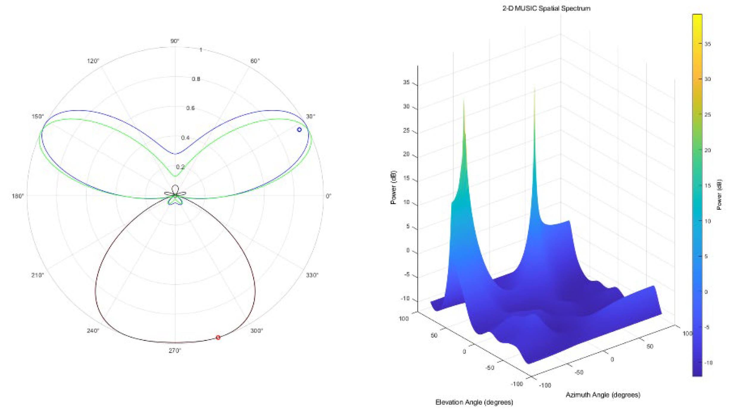
Considering the space spanned by signal dimension, s p a n ( B ) s p a n ( P H [ i , r ] ) s p a n ( P H [ j , r ] ) can be obtained. If N 2 M , the intersection subspace is empty between s p a n ( H [ i , r ] ) and s p a n ( H [ j , r ] ) when the compression method is not exploited. After the compression matrix processing, SSA can be realized only when the intersection subspace exists. This is shown in Figure 3b.
If the transmission channel between communicating nodes satisfies the independent Gaussian distribution, the basis vector of the intersection subspace of a pair of source node equivalent channel matrices P H [ i , r ] and P H [ j , r ] cannot be located in the intersection subspace of the other pair of source node equivalent channel matrices. Therefore, the matrix B is a full rank matrix with full probability, which ensures the decidability of the signal s by the relay.
The subspace alignment condition of the compressed signal (Equation (13)) holds if and only if there are at least d t o t a l 2 2 M + d i , j basis vectors in the signal space formed by P T , which are located in the [ H [ i , r ] H [ j , r ] ] T null space of the communication pair ( i , j ) . Row d t o t a l 2 2 M + d i , j of matrix P is located in [ H [ i , r ] H [ j , r ] ] T null space. Therefore, the null space dimension of [ P H [ i , r ] P H [ j , r ] ] is not less than d i , j . The precoding matrices V [ i , j ] and V [ j , i ] can always be found such that Equation (13) holds. This condition also makes r a n k ( P ) d t o t a l 2 true. That is, P is full rank.

3. Results

In this section, some simulations are given to verify the effectiveness of our proposed method. In the following simulations, we assume that all the nodes are equipped with Uniform Linear Array (ULA), as well as with M transmit elements and N receive elements that are separated by half a wavelength. Other specific simulation parameters are shown in Table 1.

3.1. Analysis of MIMO Channel Characteristics

Assuming that the communication node is in the slowly changing condition of the far-field plane wave in the relay propagation environment, the semi-static channel transmission response H [ R , i ] can be obtained. The ideal propagation conditions make it possible to separate multiple antenna channels at the relay side. At this point, channels H [ R , i ] and H [ R , j ] need to satisfy:
( H [ R , i ] ) H H [ R , j ] E { H [ R , i ] 2 } { H [ R , j ] 2 } 0
The convergence characteristics of different fading channels can be considered by Formula (15). The interpretation of (15) is that the channel directions become asymptotically orthogonal. This is because the propagation paths of the antenna experience independent fading, and the probability of each independent propagation path entering shadow fading at the same time is very low. Spatial diversity gain can be obtained with multiple antennas. The channel matrix H [ R , i ] varies with time and is a random variable. If the variables satisfy Equation (16), the random channel matrix H [ R , i ] exhibits channel hardening properties. That is, the channel fading gradually becomes deterministic and approaches hardening.
H [ R , i ] 2 E { H [ R , i ] 2 } 1
With the increasing number of antennas, all singular values of the random matrix H [ R , i ] obey a certain distribution function. All eigenvalues have the same distribution and are gradually replaced by the mean.
Consider the fading channel hardening phenomenon in N-dimensional space as shown in Figure 4. The average value of the normalized instantaneous channel gain is H 2 / E { H 2 } . It can be seen from the comparison of the channel hardening of different antenna number probability and random realization that all schemes gradually converge with the increase of the number of antennas. In particular, when the number of antennas is greater than 50, the convergence tends to be stable. Channel parameters will gradually change from randomness to determinism. This feature can ensure that communication nodes use simple linear precoding to replace complex nonlinear precoding and real-time precoding.
In wireless communication, electromagnetic waves may arrive at the receiver via many different paths. In the process of transmission through the wireless channel, it may pass through the direct line of sight (LoS) path or through the plane reflection. Since the multiple copies of the original transmission signal propagate at different distances, they arrive at the receiver at different times and have different average power levels. A traditional fading channel simulation technology, tapped delay line, is used by people to model impulse response. Each tap represents the sum of multipath signals arriving at the same time. Since signals arriving later have greater path loss, the tap amplitude usually decreases over time. The average power and delay of each tap are displayed as channel impulse responses, also known as power delay profile (PDP). Three taps (signal paths) are designed using Jakes’ fading simulator. In order to study the propagation characteristics of a Rayleigh fading channel, a 2 × 2 MIMO channel is constructed. The power delay profile and response of each channel are measured. The measurement results are shown in Table 2 and Table 3.
To combat channel fading, data packet retransmission or practical channel error correction codes are generally used. As can be seen from the figure, the fading characteristics of different channels are very different, which has a great impact on data transmission. In the past, fading was regarded as an unfavorable factor, which was often solved by equalization or diversity techniques. MIMO technology not only does not try to eliminate multi-path signals but makes full use of multi-path vectors in spatial propagation and optimizes transmission and reception as a whole. The signals of the same sub-channel, synthesized under different propagation paths, are extracted from multiple antennas, and the optimal signal is selected as the received signal of this sub-channel through analysis and comparison. This can effectively utilize random channel fading and multipath propagation to increase the transmission rate.
When the transmit power of a single antenna remains unchanged, increasing the number of antennas can increase the average signal-to-noise ratio (SNR) at the receiving end by coherently combining multiple signals. The array gain is strongly related to the logarithm of the number of antennas. Array gain can improve system radiated energy efficiency. When the coverage remains unchanged, increasing the number of antennas can reduce the transmit power of the antennas, which in turn can reduce the requirements for the linear range of the power amplifier of the device. If the transmit power of a single antenna remains the same, the total power of massive MIMO will even decrease.
The method proposed in this paper utilizes a precoding vector so that pairs of users exchanging information are aligned in the same direction in signal space. The different directions are kept in opposition to each other to avoid interference. The relay performs physical layer network coding on the received superimposed signal. In the design, it is necessary to comprehensively consider whether the constraints of each user on the alignment are satisfied. Take three nodes as an example:
s p a n ( H [ r , 1 ] v [ 1 , 1 ] ) = s p a n ( H [ r , 2 ] v [ 1 , 2 ] ) s p a n ( H [ r , 2 ] v [ 2 , 2 ] ) = s p a n ( H [ r , 3 ] v [ 1 , 3 ] ) s p a n ( H [ r , 3 ] v [ 2 , 3 ] ) = s p a n ( H [ r , 1 ] v [ 2 , 1 ] )
Three network coded signals are obtained from independent codewords at the relay. Consider M × 1 vector q that lies in R ( A 1 ) R ( A 2 ) , where R ( ) represents the column space of a matrix. A 1 and A 2 are M × M random matrices whose entries are drawn from i.i.d. complex Gaussian distribution N C ( 0 , 1 ) . There exists q i C M × 1 , i = 1 , 2 , such that q = A 1 q 1 = A 2 q 2 . This can be rewritten in matrix form as
[ I M A 1 0 I M 0 A 2 ] [ q q 1 q 2 ] = P Q = 0
The cross subspace dimension of R ( A 1 ) R ( A 2 ) can be found by computing the null space of P . Since the elements of the matrix A 1 and A 2 satisfy the complex Gaussian i.i.d., the high probability satisfies that the rank of the matrix P is 2M. Therefore, we can draw the conclusions that (18) has solutions and exist q by exploiting the rank-nullity theorem. The node selects the optimal precoding vector within the signal space dimension, so that the aligned pairs of different users remain independent of each other during transmission. Further, the general formula of formula (4) can be obtained. The signal is aligned to three directions in the signal space dimension, as shown in Figure 5.
The relay receives the superimposed signals transmitted in different alignment directions and performs decoding and detection. There is no mutual interference between superimposed signals, and simple linear independent decoding can be performed ( u [ R , i ] ) H u [ R , j ] = 0 , i j . By applying the physical network coding modulation–demodulation mapping principle, the relay encodes the decoded symbols. It must be emphasized that the intersection subspaces of information exchange pairs do not need to be orthogonal to each other.

3.2. Spectral Efficiency

The key idea of the method proposed in this paper is to reasonably choose the beamforming vector within the signal space such that the transmitted signals from two nodes are aligned to the 1-dimension of the intersecting subspace. The relay performs decoding and retransmission of separable superimposed signals. The relay designs a precoding vector with zero interference to eliminate inter-node interference during broadcast transmission. In a 3-user channel, TDMA scheme requires six time slots to implement data exchange between users through the relay, and its multiplexing gain is η = 1 . The multiuser MIMO (MU-MIMO) scheme requires four orthogonal time slots to implement data exchange between users through beamforming vector optimization. The multiplexing gain is η = 1.5 . The proposed scheme achieves data exchange between users in two time slots through signal space compression, and its multiplexing gain is η = 3 . Using these proposed signaling methods, it is shown that the capacity of the MIMO channel is characterized as η M log ( S N R ) + ο ( log ( S N R ) ) in the interference limited environment [29]. Then we compare the achievable capacity of different transmission techniques with that of the signal space under the non-saturated SNR regime. The slope of the curve in Figure 6 represents the multiplexing gain that the scheme can achieve, further reflecting the ability of data exchange and transmission. Throughput refers to the number of information bits correctly transmitted in a unit time, and its transmission capacity can be characterized by channel capacity. It can be seen from Figure 6 that capacity curve of proposed scheme has the steepest slope. Meanwhile, The TDMA curve is the flattest. The corresponding content has been added to the upper paragraph of Figure 6. In Figure 6, the proposed method can achieve greater potential than conventional TDMA and multi-user MIMO (MU-MIMO) schemes.
In the following simulations, a cooperative transmission network with K = 10 nodes and different numbers of antennas is considered. In the Gaussian local scattering channel model, the angular standard deviation (ASD) φ = 10 . Figure 7 shows the effect of the number of relay antennas on the average sum spectral efficiency (SE). When the relay receives the superimposed signal aligned in the signal space, it performs local decoding. We chose multi-node minimum mean-squared error (M-MMSE), single-node minimum mean-squared error (S-MMSE), regularized zero-forcing (RZF), ZF, and maximum ratio (MR) combining as the decoding method. In Figure 8, the performance of M-MMSE is the best. In order to reduce the computational complexity, approximate calculation is usually adopted. The performance of RZF and ZF is very close when the number of antennas is large. But when the number of antennas is insufficient, the ZF performance drops sharply. This is mainly because there are not enough degrees of freedom against interference. Also note that the performance of the S-MMSE scheme is only slightly lower than that of the M-MMSE scheme. Although the MR scheme has the worst performance, it does not require matrix inversion and thus has the lowest computational complexity.
A fading channel h C M is spatially uncorrelated if the channel gain h 2 and the channel direction h / h are independent random variables, and the channel direction is uniformly distributed over the unit-sphere in C M . The channel is otherwise spatially correlated. Practical channels are generally spatially correlated, also known as having space-selective fading. Therefore, correlated Rayleigh fading channels such that h [ i , j ] N C ( 0 M , R [ i , j ] ) , where R [ i , j ] C M × M is the positive semi-definite spatial correlation matrix and it is also the covariance matrix due to the zero mean. The normalized trace β [ i , j ] = t r ( R [ i , j ] ) / M determines the average channel gain from one of the antennas at transmitter I to receiver j. Uncorrelated Rayleigh fading with R [ i , j ] = β [ i , j ] I M is a special case of this model. Figure 8 shows the cumulative distribution function (CDF) curves of SE changes at any node in the transmission network. The direction of arrival of the array elements in the MIMO channel is non-omnidirectional and non-uniform, so the correlation characteristics of the channel transfer function and the performance of the wireless channel are closely related to the corresponding spatial distance vector. Through the simulation comparison of uncorrelated Rayleigh fading channel and Gaussian local scattering channel model, the CDF curve with spatial correlation is on the right. The CDF curve of uncorrelated channels is steeper, and the channel statistical capacity is larger. Therefore, it can be concluded that the stronger the correlation between the antennas, the smaller the channel capacity, and the slower the CDF curve of the transmission capacity. The transmission capacity is less than that of an independent uncorrelated Rayleigh channel.
The best detection algorithm for nonlinear detection is Maximum Likelihood Received Detection (ML), which is especially beneficial for obtaining the smallest error rate. However, the complexity of ML grows exponentially with transmit antenna and modulation order. When the antenna dimension and modulation order are large, it cannot be applied in practical systems. The detection algorithms of linear detection mainly include zero forcing (ZF) algorithm and minimum mean square error (MMSE) algorithm. They are simple to implement but have poor bit error rate performance. When the transmission channel H is an ill-conditioned matrix, that is, when there is a correlation, the interference between the data streams is relatively large. The channel matrix H is subjected to sorted QR decomposition H = Q R to generate a set of permutation sequences, and at the same time, the unitary matrix Q and the upper triangular matrix R , whose elements above the diagonal are ordered, are obtained. In particular, the upper diagonal elements contain all the information of the channel correlation.
Wideband signals will cause more serious nonlinear effects, which is not conducive to the transmission of high-order modulated signals. At the same time, in order to meet the needs of satellite communication for high-speed data transmission, 16QAM modulation is adopted in this paper. The transmitter uses an 8-order raised cosine roll off filter with a roll off factor of 0.3 to realize pulse shaping filtering. At the receiving end, a corresponding raised cosine roll off filter is used for matched filtering. It can be seen from Figure 9 that MMSE usually has better decoding performance than ZF due to the lack of amplification noise. When linear correlation is introduced between channel matrix columns, an ill conditioned matrix is formed. The small error in the coefficients has a great harmful effect on the decoding, and the decoding performance of MMSE and ZF decreases sharply. In order to reduce the noise enhancement, we use QR decomposition to reduce correlated condition. In particular, the ZF decoder based on QR decomposition provides performance improvement in case of ill-conditioned channels due to the way it considers only the well-conditioned elements of the channel. This method is robust to correlated channels. The method proposed in this paper leads to a significant increase in throughput, but BER simulation performance is not completely consistent with theoretical analysis. This is because sometimes the calculated signaling (spatial) dimensions for aligned symbols result in the low minimum distance between the symbols, and this affects BER performance. This problem is overcome by adding redundant antennas at every user and calculating the corresponding precoding vectors to obtain the flexibility in the selection of orthogonal signaling dimensions as well as to simplify the decoding at the relay.
The sum rate is used to characterize the channel capacity characteristics of all users in the system. As shown in Figure 10, the slope of the curve represents the approximate system degrees of freedom. The system transmission efficiency can be improved by increasing the number of users or sending more independent streams at the same time. In order to increase the degree of freedom of the system, traditional communication technologies must consume more time, frequency or airspace resources. The advantages brought by large-scale antennas cannot be fully exploited by using multiple access technology. The method proposed in this paper studies the superposition characteristics and signal spatial structure of signals in different degrees of freedom and designs separable superimposed signals through distribution characteristics to eliminate intersymbol interference. Any node in the satellite network may be the transmitter or receiver. The method can flexibly configure the number of antennas at the transceiver by combining with the existing schemes. When the number of antennas is greater than the method requirements, the antenna selection technology can be used to obtain the selection gain.

3.3. Method Robustness

With the increasing demand for satellite communication in modern life, limited spectrum resources have become one of the important factors limiting the development of communication services; however, increasing the transmission signal bandwidth or using broadband signals cannot guarantee the demand for the continuous development of communication services. Therefore, in the background of current spectrum resources, the effective use of spectrum resources and the improvement of transmission efficiency are the research directions that communication researchers have been paying close attention to.
The relay node receives the signals sent by multiple nodes at the same time and broadcasts the forwarding signal to multiple nodes in the next stage. Therefore, the performance of the relay node becomes the key that restricts the performance of the entire transmission system. According to the rank-zero theorem, the dimension of the right null space of the existing scheme is 1. This means that there is only one alignment signal vector available between each interacting pair of users. Therefore, the aligned signal vectors are all fixed. In most cases, these vectors are not optimal. The bit error rate of a relay system is determined by the minimum distance to align the signal constellation points. However, the traditional scheme cannot flexibly coordinate and align the positions of the signal constellation points according to the signal space structure. To increase the distance between alignment signals, the alignment space needs to be reconstructed. Utilizing the redundant degrees of freedom introduced by the additional antennas enables the optimal selection of aligned signal vectors in the redundant space. There are more and more kinds of remote sensing images that can be obtained by satellite remote sensing. The information contained in remote sensing images also tends to be diversified and complex. Figure 11 shows the performance comparison. The method proposed in this paper is used to process remote sensing data acquisition and transmission to realize the fusion of remote sensing images. Figure 11b greatly improves the effectiveness and reliability of transmission by optimizing the spatial structure of the signal and suppressing interference signals. It is found that Figure 11b can obtain more detailed remote sensing images than Figure 11a.

4. Discussion

4.1. Result Analysis

Whether it is interference alignment or signal space alignment, the DOF of messages W [ j , i ] and W [ i , j ] transmitted by a pair of nodes i and j exchanging information is generally the same, that is, symmetrical transmission. For example, the essence of the K-node multiple pairs bidirectional relay transmission algorithm is the process of eliminating K / 2 rings [30]. The essence of the K-node MIMO channel SSA and PNC algorithm is the process of eliminating K ( K 1 ) / 2 rings [31]. The essence of the K-node multi-directional relay successful NC algorithm is the process of eliminating one K-ring [32]. Therefore, the common typical algorithms can be reduced to a special case or subset of the method proposed in this paper. This method has more general applicability.
According to the cut-set boundary analysis of the degrees of freedom of the multidirectional relay channel, the total degrees of freedom in the transmission system can be obtained as: d t o t a l = i = 1 K j S i d i , j . The upper bound of the degree of freedom of the transmission node i is: j S i d i , j d i u p p e r = min { min { M , N } , min { ( K 1 ) M , N } } . Therefore, the degree of freedom of the whole network is d t o t a l i = 1 K d i u p p e r = min { K M , K N } . Meanwhile, it is necessary to consider the cut sent by K nodes to the relay and the cut sent by the relay to K nodes. The upper bound of the degree of freedom of the whole network is following:
d t o t a l min { K M , K N , 2 K M , 2 N } = min { K M , 2 N }
Currently, only [33,34] analyze the maximum reachable DoF in the entire domain, and other algorithms only give piecewise local maximum reachable DoF.

4.2. Antenna Configuration

The idea of signal space alignment comes from interference alignment. The beamforming vector is designed to align several signals to the same dimension of the signal space to improve the utilization of space resources. In the co-channel transmission process, mutual interference between transmitted signals is avoided. By reducing the number of independent streams propagating over the air by signal superposition, the requirement of antenna configuration conditions is relieved. s p a n ( H r , i v j , i ) = s p a n ( H r , j v i , j ) . If M K 1 , N K ( K 1 ) / 2 and 2 M N + 1 is achieved, the degrees of freedom of K ( K 1 ) is satisfied. This is idea of traditional SSA.
In order to further improve the transmission capacity of the entire cooperative transmission network, the weight of each edge of the weighted directed graph can be extended to d. As long as the number of node antennas is not less than the number of independent streams d ( K 1 ) to be sent, the relay can implement decoding and forwarding under the condition of N d ( K 2 3 K + 3 ) . In order to further expand the constraints of antenna configuration, a compression matrix P is designed to realize the transmission of interactive data in the signal subspace. When the signal space is compressed to d K ( K 1 ) / 2 dimensions, the antenna configuration condition can be extended to N > 2 M .
Extending this improved SSA to any number of communication nodes K can more easily realize the switching of communication roles among satellites. As can be seen from Table 4, we not only break through the original antenna constraints N 2 M , but also consume fewer antennas. Meanwhile, this breaks the constraints of the number of relay antennas and node antennas, and promotes the engineering application of satellite relay transmission.
Table 5 lists the comparison of the number of antennas required by the method proposed in this paper and [34] in order to realize a certain transmission tuple. The variable T, defined in Table 2, represents the synthesis of the number of antennas required by all communication nodes and relay nodes in the transmission process. It can be seen that the ring planning and design idea based on this paper can significantly reduce the requirements for antenna resources. For a certain degree of freedom tuple d , there may be unidirectional transmission, bidirectional transmission and multidirectional transmission in the network at the same time. A node may be on multiple rings of different lengths or multiple rings of the same length at the same time. Elimination of loops in message flow graphs can significantly improve transmission efficiency.

5. Conclusions

In this paper, a signal space reconstruction method was used to study the effect of signal separability from the characteristic extraction and signal distribution characteristics of superimposed signals on different degrees of freedom. We optimized the transmission algorithm through the signal space structure to improve its adaptability to complex interference communication scenarios. Secondly, we used ring planning to exploit the potential of exchange cooperative transmission management. This can realize the joint optimization utilization of space resource optimal management and network coding. The proposed method can improve spectral efficiency and transmission reliability compared with other existing methods. Simulations and experimental data verify the effectiveness of the proposed method.

Author Contributions

Conceptualization, Y.W. and X.W.; methodology, Y.W. and X.W.; writing—original draft preparation, Y.W.; writing—review and editing, Q.L., X.W. and H.L.; supervision, H.L.; funding acquisition, Y.W. and Q.L. All authors have read and agreed to the published version of the manuscript.

Funding

This work was supported by National Key Research and Development Program of China (number 2018YFB0804103), the National Natural Science Foundation of China (number 61902297), and in part by Shaanxi Intelligent Social Development Strategy Research Center (number QTZX2181).

Data Availability Statement

Not applicable.

Conflicts of Interest

The authors declare no conflict of interest.

Abbreviations

Abbreviation Comparison Table
Amplify and ForwardAF
Decode and ForwardDF
Maximum Ratio CombiningMRC
Selective Diversity CombiningSDC
Network CodingNC
High Altitude PlatformsHAPs
Unmanned Aerial VehiclesUAVs
Common Channel InterferenceCCI
Multiple Input Multiple OutputMIMO
Single Input Single OutputSISO
Degrees of FreedomDoF
Contact Graph RoutingCGR
Multiple Access ChannelMAC
Broadcast ChannelBC
Receive Antenna SelectionRAS
Signal Space AlignmentSSA
Uniform Linear ArrayULA
Signal-To-Noise RatioSNR
Independent And Identically Distributedi.i.d
Time Division Multiple AccessTDMA
Angular Standard DeviationASD
Spectral EfficiencySE
Minimum Mean-Squared ErrorMMSE
Zero-ForcingZF
Cumulative Distribution FunctionCDF
Maximum LikelihoodML
Physical Network CodingPNC
Power Delay ProfilePDP
Mathematical Symbols
( · ) T Transpose
( · ) H Conjugate Transpose
Null ( · ) Nullspaces
rank ( · ) Rank of Matrix
E ( · ) Expectation
Tr ( · ) Matrix Trace
span ( · ) Generate Subspace
C N N-dimensional complex value

References

  1. Daneshjou, K.; Mohammadi, A.; Bakhtiari, M. Mission Planning for on-orbit Servicing Through Multiple Servicing Satellites: A New Approach. Adv. Space Res. 2017, 60, 1148–1162. [Google Scholar] [CrossRef]
  2. Liu, Y.; Luo, F. Now and Future of Remote Sensing Constellations. Satell. Netw. 2019, 3, 24–29. [Google Scholar]
  3. Li, D.; Wang, M.; Sheng, X.; Dong, Z. From Earth Observation Satellite to Earth observation Brain. Geomat. Inf. Sci. Wuhan Univ. 2017, 42, 143–149. [Google Scholar]
  4. Cola, D.; Tarchi, D.; Vanelli-Coralli, A. Future Trends in Broadband Satellite Communications: Information Centric Networks and Enabling Technologies. Int. J. Satell. Commun. Netw. 2015, 33, 473–490. [Google Scholar] [CrossRef]
  5. Corbin, B.A. The Value Proposition of Distributed Satellite Systems for Space Science Missions; Massachusetts Institute of Technology, Department of Aeronautics and Astronautics: Cambridge, MA, USA, 2015. [Google Scholar]
  6. Warty, C. Cooperative Communication for Multiple Satellite Network. In Proceedings of the IEEE Aerospace Conference, Big Sky, MT, USA, 6–13 March 2010; pp. 1–7. [Google Scholar]
  7. Wang, X.; Yang, M.; Guo, Q. Optimized Power Allocation Scheme for Land Mobile Satellite Cooperative Diversity Communications. In Proceedings of the IEEE VTC (Spring), Yokohama, Japan, 6–9 May 2012; pp. 1–4. [Google Scholar]
  8. Arti, M.K.; Bhatnagar, M.R. Beamforming And Combining in Hybrid Satellite-Terrestrial Cooperative Systems. IEEE Commun. Lett. 2014, 18, 483–486. [Google Scholar]
  9. Vieira, F.; Lucani, D.E.; Alagha, N. Load-Aware Soft-Handovers for Multibeam Satellites: A Network Coding Perspective. In Proceedings of the IEEE ASMS and SPSC, Vigo, Spain, 5–7 September 2012; pp. 189–196. [Google Scholar]
  10. Vieira, F.; Lucani, D.E.; Alagha, N. Codes And Balances: Multibeam Satellite Load Balancing with Coded Packets. In Proceedings of the IEEE ICC, Ottawa, ON, Canada, 10–15 June 2012; pp. 3316–3321. [Google Scholar]
  11. Vieira, F.; Barros, J. Network Coding Multicast in Satellite Networks. In Proceedings of the IEEE NGI, Aviero, Portugal, 1–3 July 2009; pp. 1–6. [Google Scholar]
  12. Mauger, R.; Rosenberg, C. Qos Guarantees for Multimedia Services on A TDMA-Based Satellite Network. IEEE Commun. Mag. 1997, 35, 56–65. [Google Scholar] [CrossRef]
  13. Hashimoto, Y.; Sarikaya, B. Design Of IP-Based Routing in A LEO Satellite Network. In Proceedings of the ACM WOSBIS, Dallas, TX, USA, 25–30 October 1998; pp. 81–88. [Google Scholar]
  14. Chang, H.S.; Kim, B.W.; Lee, C.G.; Min, S.L.; Choi, Y.; Yang, H.S.; Kim, D.N.; Kim, C.S. FSA-Based Link Assignment and Routing in Low-Earth Orbit Satellite Networks. IEEE Trans. Veh. Technol. 1998, 47, 1037–1048. [Google Scholar] [CrossRef]
  15. Gounder, V.V.; Prakash, R.; Abu-Amara, H. Routing in LEO-Based Satellite Networks. In Proceedings of the IEEE ETSWCS, Richardson, TX, USA, 12–13 April 1999; pp. 22.1–22.6. [Google Scholar]
  16. Fischer, D.; Basin, D.; Engel, T. Topology Dynamics and Routing for Predictable Mobile Networks. In Proceedings of the IEEE ICNP, Orlando, FL, USA, 19–22 October 2008; pp. 207–217. [Google Scholar]
  17. Fischer, D.; Basin, D.; Eckstein, K.; Engel, T. Predictable Mobile Routing for Spacecraft Networks. IEEE Trans. Mob. Comput. 2013, 12, 1174–1187. [Google Scholar] [CrossRef]
  18. Wang, J.; Li, L.; Zhou, M. Topological Dynamics Characterization for LEO Satellite Networks. Comput. Netw. 2007, 51, 43–53. [Google Scholar] [CrossRef]
  19. Kobayashi, H.; Shinonaga, H.; Araki, N.; Ito, Y. Study on Interference Between Non-GSO MSS Gateway Station and GSO FSS Earth Station Under Reverse Band Operation. In Proceedings of the Tenth International Conference on Digital Satellite Communications, Brighton, UK, 15–19 May 1995; pp. 29–57. [Google Scholar]
  20. Fortes, J.M.P.; Sampaio-Neto, R.; Maldonado, J.E.A. An Analytical Method for Assessing Interference in Interference Environments Involving NGSO Satellite Networks. Int. J. Satell. Commun. 1999, 17, 399–419. [Google Scholar] [CrossRef]
  21. Park, C.-S.; Kang, C.-G.; Choi, Y.-S.; Oh, C.-H. Interference Analysis of Geostationary Satellite Networks in the Presence of Moving Non-Geostationary Satellites. In Proceedings of the International Conference on Information Technology Convergence & Services, Cebu, Philippines, 11–13 August 2010; pp. 1–5. [Google Scholar]
  22. Guidotti, A.; Icolari, V.; Tarchi, D.; Vanelli-Coralli, A. An Interference Estimation Technique for Satellite Cognitive Radio Systems. In Proceedings of the ICC 2015, London, UK, 8–12 June 2015; pp. 892–897. [Google Scholar]
  23. Hyhty, M. Frequency Sharing Between FSS And BSS Satellites in the 17.3–18.4 GHz Band. In Proceedings of the Advances in Wireless and Optical Communications (RTUWO), Riga, Latvia, 15–16 November 2015; pp. 176–179. [Google Scholar]
  24. Sharma, S.K.; Chatzinotas, S.; Ottersten, B. In-Line Interference Mitigation Techniques for Spectral Coexistence of GEO and NGEO Satellites. Int. J. Satell. Commun. Netw. 2016, 34, 11–39. [Google Scholar] [CrossRef]
  25. Zhang, C.; Jiang, C.; Kuang, L.; Jin, J.; He, Y.; Han, Z. Spatial Spectrum Sharing for Satellite and Terrestrial Communication Networks. IEEE Trans. Aerosp. Electron. Syst. 2019, 55, 1–15. [Google Scholar] [CrossRef]
  26. Wang, Y.; Ma, S.; Liu, Q.; Liu, Y.; Li, H. MIMO Relay Channel Signal Transmission in Transformed Subspace. Digit. Signal Process. 2016, 57, 46–55. [Google Scholar] [CrossRef]
  27. Cheng, H.; Yuan, X.; Tan, Y. Generalized Compute-Compress-and-Forward. IEEE Trans. Inf. Theory 2019, 65, 462–481. [Google Scholar] [CrossRef]
  28. Ding, T.; Yuan, X.; Liew, S. Algorithmic Beamforming Design for MIMO Multiway Relay Channel with Clustered Full Data Exchange. IEEE Trans. Veh. Technol. 2018, 67, 10081–10086. [Google Scholar] [CrossRef]
  29. Lee, N.; Lim, J.B.; Chun, J. Degrees of Freedom of the MIMO Y Channel: Signal Space Alignment for Network Coding. Inf. Theory IEEE Trans. 2010, 56, 3332–3342. [Google Scholar] [CrossRef]
  30. Guo, J.; Zhao, N.; Yang, Z.; Yu, F. Proactive Jamming Toward Interference Alignment Networks: Beneficial and Adversarial Aspects. IEEE Syst. J. 2019, 13, 412–423. [Google Scholar] [CrossRef]
  31. Xin, H.; Yuan, X.; Liew, S.C. Multi-Pair MIMO Two-Way Relaying: A Principal-Angle Perspective. Signal Processing IEEE Trans. 2016, 64, 380–394. [Google Scholar]
  32. Chaaban, A.; Aydin, S. Multi-Way Communications: An Information Theoretic Perspective. Found. Trends Commun. Inf. Theory 2015, 12, 185–371. [Google Scholar] [CrossRef]
  33. Bafghi, A.H.A.; Jamali, V.; Nasiri-Kenari, M.; Schober, R. Degrees of Freedom of the K-User Interference Channel Assisted by Active and Passive IRSs. IEEE Trans. Commun. 2022, 70, 3063–3080. [Google Scholar] [CrossRef]
  34. Lee, B.; Lee, N.; Ha, N.; Shin, W. On the Degrees-of-Freedom for Relay-Aided MIMO Interference Channels with Partial and Delayed CSI. IEEE Wirel. Commun. Lett. 2021, 10, 306–310. [Google Scholar] [CrossRef]
Figure 1. Inter satellite link directed graph.
Remotesensing 14 04474 g001
Figure 2. Directed graph of information interaction among nodes. (a) Initial message directed graph, (b) message directed graph after eliminating 2-ring, and (c) message directed graph after eliminating 3-ring (1,2,3).
Remotesensing 14 04474 g002
Figure 3. Distribution change of equivalent channel spanned space of nodes. (a) Traditional SSA ( N < 2 M ), (b) SSA ( N 2 M ), (c) SSA after space compression ( N 2 M ).
Remotesensing 14 04474 g003
Figure 4. Comparison of channel hardening characteristics.
Remotesensing 14 04474 g004
Figure 5. Spatial distribution of alignment signal angle.
Remotesensing 14 04474 g005
Figure 6. Capacity of different schemes.
Remotesensing 14 04474 g006
Figure 7. Average sum SE as a function of the number of relay antennas for different combining schemes. (a) DoF = 1, (b) DoF = 2, (c) DoF = 4.
Remotesensing 14 04474 g007
Figure 8. CDF of different schemes.
Remotesensing 14 04474 g008
Figure 9. The effect of channel conditions on scheme performance.
Remotesensing 14 04474 g009
Figure 10. Sum rate of space compression.
Remotesensing 14 04474 g010
Figure 11. The proposed technology is applied to remote sensing imaging. (a) Traditional MIMO transmission. (b) The proposed scheme.
Remotesensing 14 04474 g011
Table 1. Simulation Parameters.
ParametersValue
node antennasM
relay antennasN
K3
taps3
Number of channelsM × N
frequency2.4 GHz
FFT Length64
modulation16 QAM
band width20 MHz
Roll off factor0.3
Table 2. Measured value of path delay (unit: ns).
Channel 1Channel 2Channel 3Channel 4
path 1115.31 124.25 107.84 115.79
path 24993.75 4995.00 4995.50 4987.51
path 39991.25 9992.50 9990.00 9981.25
Table 3. Measured value of path loss (unit: dB).
Channel 1Channel 2Channel 3Channel 4
path 1−2.01 −2.13 −2.00 −2.12
path 2−5.13 −4.86 −5.15 −4.89
path 3−11.97 −12.11 −12.04 −12.05
Table 4. Antenna configuration conditions of different schemes.
KSchemeMNTotal Number
4SSA4622
Proposed3719
5SSA61040
Proposed41333
6SSA81563
Proposed52151
Table 5. Multicast transmission strategy based on ring planning.
K(d12, d13, d14, … d42, d43)NTproposedT [34]
3(2, 0, 0, 0, 2, 0, 2, 0, 0, 0, 0, 0)41116
4(1, 1, 0, 0, 1, 2, 0, 0, 1, 2, 0, 0)61730
4(3, 0, 0, 1, 2, 1, 1, 1, 0, 2, 0, 0)72135
4(3, 0, 0, 1, 3, 0, 1, 0, 3, 2, 0, 2)103350
Publisher’s Note: MDPI stays neutral with regard to jurisdictional claims in published maps and institutional affiliations.

