Article

Expandable On-Board Real-Time Edge Computing Architecture for Luojia3 Intelligent Remote Sensing Satellite

1
School of Computer Science, Hubei University of Technology, Wuhan 430068, China
2
State Key Laboratory of Information Engineering in Surveying, Mapping and Remote Sensing, Wuhan University, Wuhan 430079, China
3
School of Computer Science, Huanggang Normal University, Huanggang 438000, China
*
Author to whom correspondence should be addressed.
Remote Sens. 2022, 14(15), 3596; https://doi.org/10.3390/rs14153596
Submission received: 14 June 2022 / Revised: 17 July 2022 / Accepted: 25 July 2022 / Published: 27 July 2022

Abstract

:
Since the data generation rate of high-resolution satellites is increasing rapidly, to relieve the stress of data downloading and processing systems while enhancing the time efficiency of information acquisition, it is important to deploy on-board edge computing on satellites. However, the volume, weight, and computability of on-board systems are strictly limited by the harsh space environment. Therefore, it is very difficult to match the computability and the requirements of diversified intelligent applications. Currently, this problem has become the first challenge of the practical deployment of on-board edge computing. To match the actual requirements of the Luojia3 satellite of Wuhan University, this manuscript proposes a three-level edge computing architecture based on a System-on-Chip (SoC) for low power consumption and expandable on-board processing. First, a transfer level is designed to focus on hardware communications and Input/Output (I/O) works while maintaining a buffer to store image data for upper levels temporarily. Second, a processing framework that contains a series of libraries and Application Programming Interfaces (APIs) is designed for the algorithms to easily build parallel processing applications. Finally, an expandable level contains multiple intelligent remote sensing applications that perform data processing efficiently using base functions, such as instant geographic locating and data picking, stream computing balance model, and heterogeneous parallel processing strategy that are provided by the architecture. It is validated by the performance improvement experiment that following this architecture, using these base functions can help the Region of Interest (ROI) system geometric correction fusion algorithm to be 257.6 times faster than the traditional method that processes scene by scene. In the stream computing balance experiment, relying on this architecture, the time-consuming algorithm ROI stabilization production can maintain stream computing balance under the condition of insufficient computability. We predict that based on this architecture, with the continuous development of device computability, the future requirements of on-board computing could be better matched.

Graphical Abstract

1. Introduction

The traditional pattern of obtaining useful information from remote sensing satellites contains three major steps: on-board data generation, data downloading, and on-ground data processing. On the one hand, with the growth in the spatial resolution, spectral resolution, and temporal resolution of modern remote sensing satellites, the data generation rate is increasing rapidly. This situation brings massive stress to data downloading and processing systems, and the information acquisition delay is also becoming longer. On the other hand, users are increasingly demanding the timeliness of information acquisition from remote sensing satellites. A shorter delay or instant response is required in many high-timeliness applications, such as disaster prevention and mitigation, earthquake early warning, and rescue guidance. Thus, task-driven on-board processing is provided to solve this contradiction.
To relieve the stress of data downloading and processing systems, it is important to deploy on-board edge computing on satellites. Ideally, with on-board data picking, processing, and downloading, a massive amount of raw data has been concentrated into little useful information that can be downloaded and delivered immediately [1,2]. Several achievements have been made in this area; for example, the Coastal Ocean Imaging Spectrometer (COIS) in the Naval Earth Map Observer (NEMO) satellite is used to characterize the littoral region environment. COIS uses the Optical Real-time Adaptive Spectral Identification System (ORASIS) to accomplish spectral filtering and spatial filtering, before finally generating battlefield environmental information and a direct downlink [3]. The Australian satellite, FedSat, carried a demonstration device for the feasibility of reconfigurable computing technology in space called High Performance Computing (HPC-I). Using this device in conjunction with an optical sensor, the system could detect and monitor natural disasters and would be capable of producing useful information that could be broadcast directly within rapid timeframes [4]. The Yet Another Mission (YAM-3) satellite launched by the US Space Development Agency carried an edge computing system called Prototype on-Orbit Experimental Testbed (POET) based on SpaceCube v3.0 [5] technology, which can perform autonomous data fusion and processing on board and is used by the US military to detect and track a target on the ground or in the sea or air. Furthermore, several Field Programmable Gate Array (FPGA)-based methods have been presented for on-board processing, such as image ortho-rectification [6], feature point detection and matching [7], object detection [8,9], and image classification [10,11].
In fact, in the harsh space environment, the design of the on-board processing system will always be limited. The natural radiation from stable low-flux Galactic Cosmic Rays (GCR) and infrequent high-flux Solar Particle Events (SPE) can have an impact on on-board devices [12]. Depending on the radiation environment in which the on-board device is located, ionizing radiation can produce radiation effects including Single Event Effect (SEE) [13], Displacement Damage (DD), and Total Ionizing Dose (TID) [14]. The general approach to mitigating SEE is redundancy techniques which are based on hardware, software, and information redundancy [15], but this will cause a lot of resource consumption. To solve this problem, Jacobs proposed a Reconfigurable Fault Tolerance (RFT) framework to dynamically adjust a system’s level of redundancy and fault mitigation [16]. Glein proposed an Adaptive Single Event Effect Mitigation (ASEEM) method for FPGA-based processing systems, which dynamically adjusts the state of the processing system according to different space radiation conditions to save system resources [17]. Sabogal proposed Hybrid, Adaptive Reconfigurable Fault Tolerance (HARFT), a reconfigurable framework for environmentally adaptive resilience in hybrid space systems [18]. As hybrid processors become a trend and high-performance commercial devices are used for on-board computing [19], the related research is also underway. The Science Data Processing Branch at National Aeronautics and Space Administration (NASA) Goddard Space Flight Center (GSFC) has pioneered a hybrid-processing approach that combines radiation-hardened and commercial components while emphasizing a novel architecture harmonizing the best capabilities of Central Processing Units (CPUs), Digital Signal Processing (DSPs), and FPGAs [20]. Müller refined the methodology for assessing the Fault Detection, Isolation, and Recovery (FDIR) design of on-board computers in space systems by introducing a library of FDIR routines [21].
Although DSPs and FPGAs are used in most on-board embedded systems, Graphics Processing Units (GPUs) are another feasible option. GPUs have already been implemented on board for anomaly detection of hyperspectral images [22] and spaceborne Synthetic Aperture Radar (SAR) processing [23]. Considering that GPUs are implemented in many remote sensing fields, such as hyperspectral image compression, classification, unmixing, and detection, they have already substantially enhanced the efficiency of the algorithms. Additionally, GPUs are also widely used in intelligent remote sensing applications, such as object detection, semantic segmentation, and change detection. It is predictable that using GPU and CPU on board will make the processing system more efficient and expandable.
In previous work, embedded GPUs have been used to implement on-board stream computing for sensor correction processing [24]. Through the strategy of multimodule cooperation, scene-by-scene standard image product processing for flow-in data is realized. To achieve this goal, the data generation rate, processing time consumption, and computability need to be strictly matched. Predictably, once a different time-consuming application is deployed, it is nearly impossible to maintain a strict balance in such a strategy.
The basic truth is that in the harsh space environment, limited by the volume, weight, and power consumption, it is impossible to deploy as many computing devices on board as every application needs. Moreover, another truth is that only a small part of the data contains useful and important information on most occasions; other unimportant data are disposable. Therefore, to build an expandable on-board processing system for the deployment of various intelligent applications, first, the accurate geographic position of the data must be calculated in time to locate the ROI. Second, a multi-buffer strategy must be introduced to balance the difference between data generation and data processing for applications, such as fusion, georectification, ROI extraction, cloud-cover detection, target recognition, and change detection.
This manuscript proposes an expandable on-board edge computing architecture that can not only provide autonomy for the computing performance of heterogeneous hardware but also meet the needs of different intelligent applications as much as possible while balancing the difference in data generation and data processing speed. In Section 2, an instant geographic locating algorithm is proposed as the key base function of the architecture to assist on-board applications to quickly obtain the geographic position of the current imaging data and extract ROI data while the data continuously flow-in, to ensure that precious computability is used for important data. In Section 3, based on the SoC hardware of Luojia3, an on-board edge computing architecture is proposed, which provides a standard application template, base functions, and optimization strategies for developers in realizing on-board stream computing for various applications.

2. Instant Geographic Locating

As a key step in on-board processing, instant geographic locating is extremely important for quickly locating the ROI area data and filtering irrelevant data. It is the premise of realizing multiple on-board applications under limited on-board computability and is the underlying core function of the architecture of this manuscript.

2.1. Satellite Position and Attitude Interpolation

To obtain the geographic location of the pixels on the remote sensing satellite image and to calculate the current imaging position in real-time, it is necessary to obtain the exterior orientation elements, including the satellite position and the attitude information at the imaging instant. Mainstream high-resolution satellites have independent position and attitude measurement devices and independently obtain information periodically. Therefore, when calculating the geographic location, it is necessary to obtain the value at the imaging instant by interpolating the discrete data.
The original satellite position data of the satellite is a position and velocity vector from Global Positioning System (GPS) or Beidou-2 (BD2) with a certain frequency. The coordinates ( X s , Y s , Z s ) of the projection center of each image at time t are interpolated from the GPS or BD2 data by a cubic polynomial model.
{ X s ( t ¯ ) = k 0 + k 1 t ¯ + k 2 t ¯ 2 + k 3 t ¯ 3 Y s ( t ¯ ) = m 0 + m 1 t ¯ + m 2 t ¯ 2 + m 3 t ¯ 3 Z s ( t ¯ ) = n 0 + n 1 t ¯ + n 2 t ¯ 2 + n 3 t ¯ 3
where k 0 , k 1 , k 2 , k 3 , m 0 , m 1 , m 2 , m 3   n 0 , n 1 , n 2 , and n 3 are the coefficients of the cubic polynomial models, which are fit by the observed data; t ¯ is the normalized imaging time, which is calculated as follows:
t ¯ = t t s t a r t t e n d t s t a r t
where t s t a r t and t e n d are the start and end times of the satellite position data, respectively.
The original attitude data are the attitude quaternion of the satellite from the star sensor or gyro with a sub-second frequency (4–8 Hz). Due to satellite jitter, the actual attitude is not smooth, and the jitter affects the original image. Therefore, to ensure that the fitting curve can pass through each observation point, the Lagrange polynomial model shown in Equation (3) is used. However, to filter the oscillation and obtain a smooth attitude, a cubic polynomial model whose detail is similar to position interpolation could be used.
{ φ ( t ) = i = 1 n φ ( t i ) W i ω ( t ) = i = 1 n ω ( t i ) W i κ ( t ) = i = 1 n κ ( t i ) W i
where W i = k = 1 k i n t t k t i t k , n is the total quaternion number for attitude interpolation, i is the index number of the attitude quaternion, and t i is the observation time of the attitude quaternion.

2.2. Strict Geometric Modeling

In addition to the exterior orientation elements of every image, the interior orientation elements are described by the look angle of the camera coordinates; they are determined by laboratory calibration before launching and updated by inflight calibration during a certain period after launching [25,26]. The strict geometric model can be established as follows:
[ tan ψ x tan ψ y 1 ] = λ · R b o d y s e n s o r · R E C I b o d y ( φ ( t ) , ω ( t ) , κ ( t ) ) · R E C F E C I ( t ) [ X X s ( t ) Y Y s ( t ) Z Z s ( t ) ]
where t is the imaging time of the scan line recorded by the camera; λ is a scale factor; ψ x   and   ψ y are the look angles; R b o d y s e n s o r is the camera install matrix calculated by inflight calibration, which can be treated as a fixed value over a long period of time; R E C I b o d y ( φ ( t ) , ω ( t ) , κ ( t ) ) is the rotation matrix from the Earth-Centered Inertial (ECI) coordinate system to the satellite body coordinate system converted by rotation angles   φ ( t ) , ω ( t ) , and   κ ( t ) , which are the pitch, roll, and yaw angles, respectively, and interpolated from the attitude observation under the ECI coordinate system by time; R E C F E C I ( t ) is the transformation matrix from the Earth-Centered Fixed (ECF) coordinate system to the ECI coordinate system; and [ X s ( t ) Y s ( t ) Z s ( t ) ] T is the position vector of the projection center in the ECF coordinate system, interpolated from the position observation by time.

2.3. ROI Location Algorithm

Based on the above satellite position and attitude interpolation method and strict geometric modeling method, the geographic coordinates corresponding to each pixel can be calculated. In order to quickly complete the calculation of the geometric position of the flow-in data and the locating of the ROI with limited on-board computability, it is necessary to reduce calculations as much as possible. This section proposes quick ROI location algorithms for both linear array sensor data and frame array sensor data separately.

2.3.1. Linear Array Sensor Data

For linear array sensor data, each line of a raw image can be considered an independent central projection imaging with independent external orientation elements. Thus, the strict geometric models corresponding to various image lines are different. In addition, the imaging line frequency of linear array sensor data is as high as 16 kHz. In the process of satellite imaging, it is impossible to complete the calculation of the positions of all image pixels and compare them with the position of the ROI because of the limitation of the computing resources on board. Therefore, for the linear array data, this manuscript adopts the locating method described below to complete the real-time computing of ROI location:
  • We establish a strict geometric model of the current imaging line;
  • We calculate the geographic position of the first and last pixels of the current line at T 0 , and obtain the points ( p 0 , q 0 ) ;
  • When T 1 = T 0 + Δ t , steps 1 and 2 are repeated to obtain the points ( p 1 , q 1 ) ;
  • We determine whether the ROI center is located in the rectangle ( p 0 , q 0 , p 1 , q 1 ); if not, we continue to repeat the above calculation steps after Δ t time;
  • If the center of the ROI is located in the rectangle ( p i , q i , p i + 1 , q i + 1 ), we calculate the exact image coordinates of the range of the ROI area.
Since only two points need to be calculated in a Δ t timespan, the above steps can be completed in several milliseconds. The flowchart of this algorithm is shown in Figure 1.

2.3.2. Frame Array Sensor Data

For the frame array sensor data, each image is a two-dimensional plane, the geographic location of each pixel can be obtained only by establishing a strict model once, and the computation amount of a single frame is as small as a single line in linear data. In this manuscript, the method described below is used to complete the real-time computing of ROI location:
  • We establish a strict geometric model of the current imaging frame;
  • We calculate the geographic position of the corner pixel of the current frame and obtain the points ( p 0 , q 0 , p 1 , q 1 );
  • We determine whether the ROI center is located in the rectangle ( p 0 , q 0 , p 1 , q 1 ); if not, we continue to repeat the above calculation step on subsequent frames;
  • If the center point of the ROI is located in the rectangle ( p i , q i , p i + 1 , q i + 1 ), we calculate the exact image coordinates of the range of the ROI area.
In general, the amount of computation for frame data is smaller than linear data, and the above steps can be completed in several milliseconds. The flowchart of this algorithm is shown in Figure 2.

3. Edge Computing Architecture

The on-board computing device of the Luojia3 satellite is mainly composed of SoC and FPGA. The SoC includes 8 GB Random Access Memory (RAM) for loading the operating system and running applications, 32 GB Flash Memory for storing applications, basic data, and configuration, and 6-core ARM64 CPU and 256-core GPU processing units, which are responsible for executing different intelligent applications. It uses Peripheral Component Interconnect Express (PCIE) and Serial Peripheral Interface (SPI) to communicate with FPGA. The FPGA is responsible for assisting the SoC with camera interaction, external storage devices, system buses, and the application upload channel. The SoC high-speed channel (PCIE) is connected to the FPGA, receives massive camera data through the FPGA, and the low-speed channel (SPI) is used to receive the platform auxiliary data and the uploaded data from the ground. The on-board computing device has the ability to dynamically deploy new applications during the lifecycle. The concept of the hardware architecture of the on-board computing device can be described in Figure 3.
The on-board processing data sources are mainly high-resolution optical cameras. On the one hand, to ensure data integrity, the hardware designer confirms that the data transfer bandwidth between the camera and the SoC meets the requirements; that is, the data generated by the camera can be in real-time and can be completely sent to the SoC. On the other hand, different on-board applications have various time consumptions, and the SoC with a limited processing ability needs to realize stream computing for a continuous influx of large amounts of data under the premise of mainly in-memory computation. This poses great challenges to the design of the expandable on-board real-time edge computing architecture. The core issues are as follows:
  • Selecting important data in real-time while the data flow in to ensure that precious computability is used for important data;
  • Shortening the execution time of a single application as much as possible;
  • When the computing is slower than the data flow-in, we ensure that continuous data can be processed in time to confirm that the processing results are synchronized with the flow-in data;
  • In the above situation, making full use of on-board transfer, storage, and computing resources to maximize the efficiency of streaming computing so that as much important data as possible can be processed.
Considering the above issues and challenges, this manuscript presents an edge computing architecture with base functions. First, as 
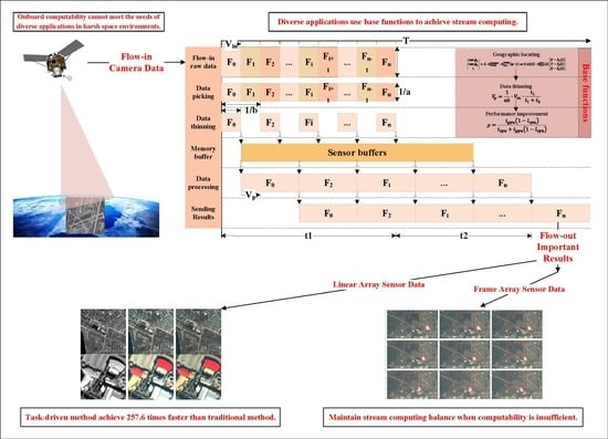
Section 2 describes, an instant geographic locating function is provided for applications to select the important data from the enormous raw data in time. Second, using the stream computing balance model, applications with different time consumptions could balance the difference between data flow-in speed and processing speed to ensure that as much important data as possible can be processed. Third, following a heterogeneous parallel processing strategy, applications can adjust their algorithms as needed to fully use on-board computability, thereby minimizing the time consumption. The details are discussed in this section.

3.1. Multilayer Structure

To better organize the base structure of the on-board edge computing architecture and make it convenient for applications to focus on algorithm logic, execution efficiency, and stream computing balance, this manuscript proposes a layered platform architecture, which mainly includes three layers:
  • The bottom layer is responsible for hardware communications and I/O works while maintaining a buffer to store image data for upper levels temporarily. On the one hand, by maintaining a small circular memory buffer space shared with the upper layer where the actual size can be configured as needed, the flow-in data are stored synchronously with the camera. On the other hand, by ensuring data integrity and consistency in the process of sending and receiving, a data transfer interface is provided to the upper layer to ensure that upper-layer applications do not need to involve hardware and data transfer details.
  • The middle layer obtains data from the circular memory buffer space shared with the bottom layer, completes the instant geographic locating and ROI locating calculation for the data, and provides the position information to the application layer. During this procedure, the data classification, which is by camera type and sensor number, is processed at the same time. The selected important data are stored in an independent memory buffer shared with the application layer. In addition, deeply optimized base functions, such as radiometric correction, geometric resampling, and other base functions, are also provided for the application layer.
  • The application layer is an expandable layer that supports the deployment of multiple applications, including radiometric correction, sensor correction, geometric correction, fusion, target detection, and change detection. A standard template is provided in this layer for all on-board applications. The template includes the following elements: program initialization and configuration reading, buffer initialization at all levels, bottom layer function initialization, middle layer function initialization, application logic, and processing results feedback. Among them, the application logic part is implemented by different applications, and the rest is completed by a template or by calling base functions.
The structure of the edge computing architecture is displayed in Figure 4.
The flowchart of a typical application using a standard template is displayed in Figure 5, in which the “Application logic” should be implemented by different applications. As Figure 5 shows, after the application is started, the camera data receiver is initialized first, then the auxiliary data receiver is initialized, and then the camera data classifier is started. All these three run as independent threads, executing concurrently with the main thread. Among them, the camera data receiver exclusively occupies the high-speed channel of the SoC and receives raw camera data into the “Camera data buffer”; the auxiliary data receiver monitors the low-speed interface of the SoC and receives auxiliary data into the “Auxiliary data buffer”; the camera data classifier monitors these two buffers while extracting the ROI data through “Instant geographic locating”, then performs “Data thinning” according to the configurations, and stores the classified data into the “Sensor buffer” for “Application logic”. After processing, the “Application logic” uses a base function to pass the processing result out of the SoC.

3.2. Stream Computing Balance Model

Due to the contradiction between the limited on-board computability and storability and the large amounts of flow-in data, it is almost impossible to complete on-board processing for all data in real-time. Therefore, selecting important data and ensuring that precious computability is used for important data is the main duty of the on-board edge computing architecture. Based on the above architecture, after the application is correctly initialized, it can obtain the geographic location of the current imaging position in real-time based on the API provided by the middle layer and select important data for processing to efficiently use the limited on-board computability.
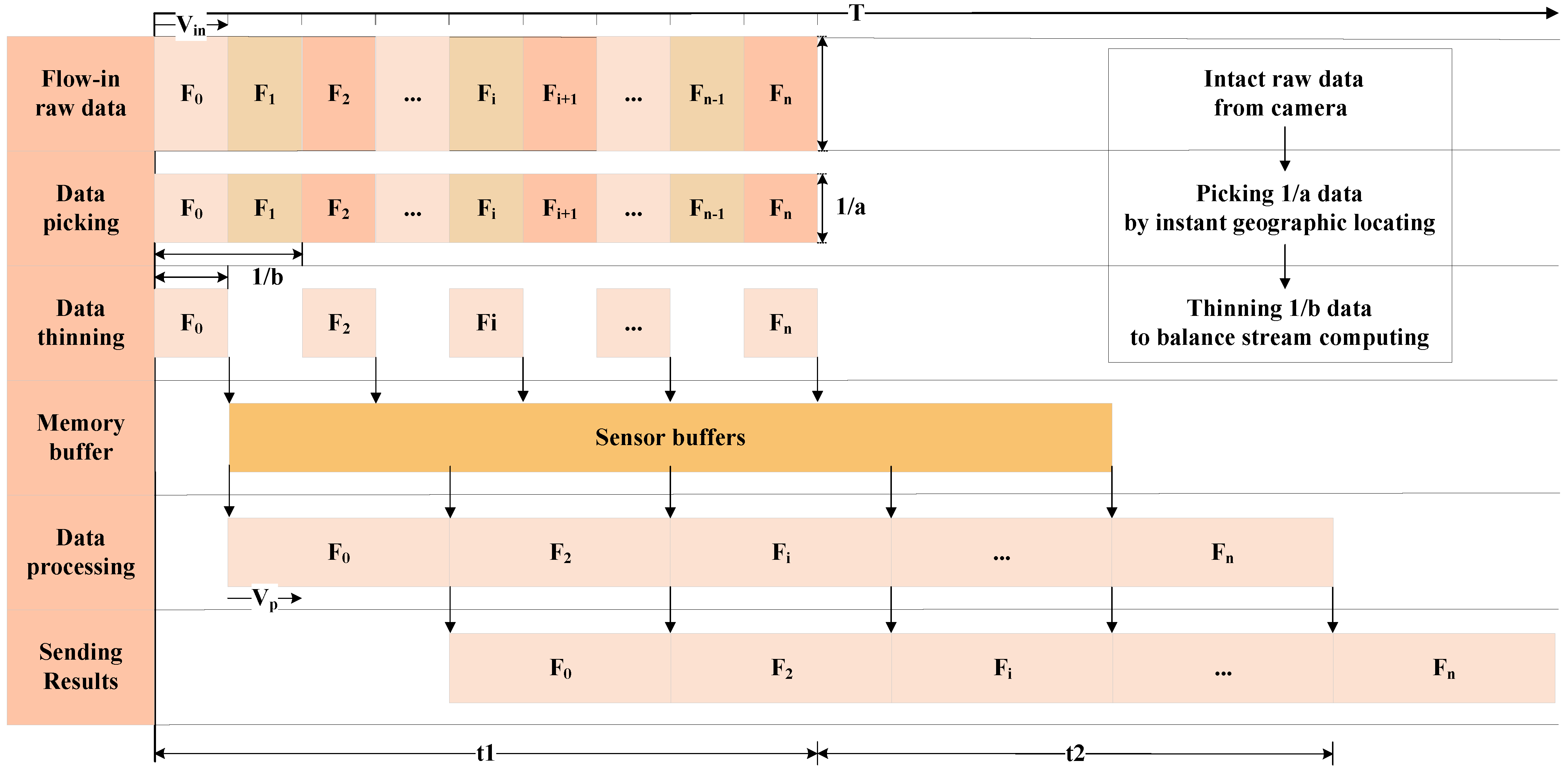
Second, when the computing is still slower than the data flow-in, the balance of stream computing is broken, and part of the data must be discarded. The traditional strategy is to complete the processing of the flow-in data as much as possible and store the data that cannot be processed in the buffer if feasible, and once the buffer is full, the new data is discarded. Another more reasonable strategy is to maintain a buffer with an appropriate size as configured by the architecture and periodically discard part of the flow-in data to balance the flow-in and computing. The traditional strategy leads to the situation where only the beginning part of the data is processed, and the later data is discarded. In contrast, the second strategy can periodically process the data according to the configured frequency, and all the processing results are distributed evenly in the time dimension. In addition, considering the relative position between the satellite and Earth, to ensure that the ground station can obtain the on-board processing results in time, the time window for on-board processing is usually not very long. When the camera starts imaging, the application on the SoC starts running synchronously. Usually, the result must be given within tens of seconds after the camera imaging is completed. Therefore, the second strategy is more adaptable and suitable than the traditional one. The processing timeline of this strategy is shown in Figure 6.
To quantitatively describe the above process, a stream computing balance model is built. Let V i n represent the data flow-in speed, V p represent the computing speed, S represent the maximum size of memory occupation during processing, including the occupation of the operating system, B u f represent the memory buffer size, M e m o r y represent the total memory size, t 1 represent the imaging time, t 2 represent the processing time after imaging, a represent the data picking coefficient, which is numerically equal to the raw data size divided by the picked data size by instant geographic locating theoretically, and b represent the data thinning coefficient when computing is slower than the flow-in.
Ideally, when the memory buffer is sufficient and the computing speed meets the following conditions, the stream computing state is steady.
{ (5a) V p V i n · t 1 t 1 + t 2 (5b) B u f + S M e m o r y (5c) B u f = V p · t 2
For most intelligent applications, V p does not satisfy Equation (5a), which means that stream computing cannot be naturally realized. In this case, after applying instant geographic locating, the equivalent data flow-in speed is reduced to 1 a · V i n ; furthermore, when the data thinning coefficient b is greater than 1, the equivalent data flow-in speed is reduced to 1 a b · V i n . Then, the stream computing conditions can be described as follows:
V p = 1 a b · V i n · t 1 t 1 + t 2
b can be calculated as follows:
b = 1 a · V i n V p · t 1 t 1 + t 2
It is important to note that the memory buffer size B u f also needs to meet Equation (5b).
The data flow-in speed V i n depends on the camera, which can be considered a fixed value for a certain satellite. When introducing a new application, the computing speed V p and the memory occupation size S of this application should be determined first. Then, the imaging time t 1 and the processing time after imaging t 2 are determined according to the task requirements.
Substituting the above values into Equation (5c) can determine whether the memory buffer size B u f meets the requirements. If the memory is sufficient, we determine the a and b values that make the minimum a · b value according to the specific requirements. Then, we set the B u f , a and b values to the application configuration to leverage the architectural foundational capabilities to realize stream computing of new applications. When the memory is insufficient, which means that B u f < V p t 2 , then the stream computing conditions can be described as follows:
V p t 1 + B u f = 1 a b · V i n · t 1
b can be calculated as follows:
b = 1 a · V i n t 1 V p t 1 + B u f
Clearly, the data thinning coefficient b needs to be further increased.
When an application starts, the platform reads the configurations and then sets parameters through the API to ensure that the stream computing of this specific application can work optimally per on-board hardware ability limitations.

3.3. Heterogeneous Parallel Processing Strategy

Any algorithm that can be implemented by a computer system can be divided into serial component W s and parallel component W p . The well-known Amdahl′s Law [27] is given as follows:
S = W s + W p W s + W p p
where p is the number of parallel cores and S is the speedup ratio of parallel computing. Theoretically, when p , the upper limit of the speedup ratio is 1 + W p W s . This means that the theoretical maximum speedup ratio of the algorithm depends on the ratio of the parallel component to the serial component of the algorithm itself. In an actual parallel system, the number of parallel cores p is limited. Due to the limitations of the chip architecture and memory access performance, it is almost impossible to achieve the upper limit of the theoretical speedup ratio. However, the analysis of the algorithm’s characteristics itself can always help developers achieve efficient optimization of the algorithm.
The classical Flynn taxonomy [
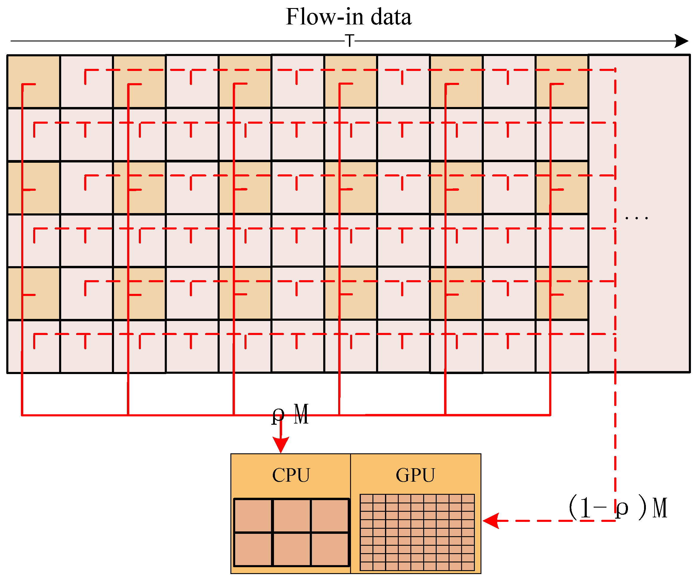
28] divides computing platforms into four categories according to the instruction flow and the data flow of the computing platform, namely, Single Instruction Single Data (SISD), Single Instruction Multiple Data (SIMD), Multiple Instruction Single Data (MISD), and Multiple Instruction Multiple Data (MIMD). Presently, the majority of mainstream hardware adopts the hardware architecture combining SISD and SIMD. The serial component of the algorithm is often executed on an SISD processor such as a CPU, and the parallel component is often executed on an SIMD processor such as a GPU to realize efficient processing. Ideally, when the performance of the GPU is sufficient to meet the needs, the algorithm can be fully parallelized. However, under the limitation of on-board computing, the performance of the GPU is usually insufficient on most occasions. Fortunately, most of the current mainstream CPUs have multiple cores, which can take part in the parallel component computing work under the premise of meeting the requirements of serial component computing, thereby shortening the overall computing time. The optimal heterogeneous parallel processing strategy can be described as follows.
Let ρ represent the proportion of the parallel component allocated to the CPU, M represent the total computing amount, l c p u represent the total CPU load for computing the serial component, V c p u represent the processing performance when the algorithm occupies multiple CPU cores for execution, and V g p u represent the processing performance when the algorithm uses a GPU to execute. The relationship between these variables can be described by Equation (11).
{ V c p u = M t c p u V g p u = M t g p u ( 1 l c p u ) V c p u V g p u = ρ M ( 1 ρ ) M
ρ can be calculated as follows:
ρ = t g p u ( 1 l c p u ) t c p u + t g p u ( 1 l c p u )
The time consumption of heterogeneous parallel processing t can be calculated as follows:
t = ρ 1 l c p u t c p u = ( 1 ρ ) t g p u
The flowchart of the heterogeneous parallel processing strategy is shown in Figure 7.
According to Equations (11) and (12), the values of t g p u and t c p u can be determined through experiments. The specific value of l c p u is more difficult to determine because too many factors affect its value, in actual use, one or two CPU cores can be reserved for l c p u . Therefore, usually, a region of value could be estimated for ρ . It is worth noting that when t g p u t c p u , the CPU multicore parallelism does not work well for this algorithm. At this time, the value of ρ is very small, which means that the CPU multicore parallelism does not suit this algorithm, and the heterogeneous parallelism is unworthy.
When applying heterogeneous parallel optimization to an algorithm, we first measure t cpu and t gpu and estimate the l cpu value; then, we substitute them with Equation (12) to obtain the optimal division of parallel components. During image processing, the data to be processed are divided into blocks and sent to the CPU and GPU according to the above division to realize the performance optimization of the algorithm. It can be seen that the optimization scheme of the specific algorithm is highly related to the specific hardware composition, ability, algorithm characteristics, etc., and the optimization cost is high. The developers of different applications can determine whether to apply this strategy according to specific situations.

4. Experiment

Considering the contradiction between the limited on-board computing and storability and the large amounts of flow-in data, this manuscript focuses on realizing an expandable on-board real-time edge computing architecture for future intelligent remote sensing satellites. In addition to being applied to the Luojia3 satellite, the architecture also aims to serve other future satellites. Therefore, to validate the effectiveness and the expansibility of this architecture, the experiments are designed as follows:
  • Performance improvement: To validate the effect of comprehensively using instant geographic locating and a heterogeneous parallel computing strategy to improve application performance, an application of the ROI fusion product production is applied and compared to the traditional method using linear array sensor data from an actual satellite.
  • Stream computing balance: To validate the ability to help time-consuming applications realize stream computing based on the stream computing balance model of this manuscript, an application of ROI stabilization production from sequence images is applied using frame array sensor data from an actual satellite.

4.1. Performance Improvement

4.1.1. Data and Experimental Design

This section uses a short strip of linear array sensor data from an optical remote sensing satellite in China that has a submeter resolution panchromatic and multispectral camera with four sensors. Each sensor has five bands, and each pixel size is 10 bits. The spatial resolution of panchromatic data is four times that of multispectral data.
A certain area in the strip is selected as an ROI with a size of 2000 × 2000 pixels; for comparison, the standard scene size is 26,000 × 29,000 pixels. The panchromatic, multispectral, and fusion image products of the ROI processed by the algorithm in this manuscript are shown in Figure 8a–c, and the zoom-in details are shown in Figure 8d–f.
To objectively measure the performance improvement effect of different algorithms, as shown in Equation (14), this manuscript uses the speedup ratio S to measure the performance improvement as follows:
S = M T 2 / M T 1 = T 1 T 2
where M represents the calculation amount, T 1 is the time consumption of the unoptimized algorithm and T 2 is the time consumption of the optimized algorithm.
According to Figure 8, the fusion product has both high spatial resolution and multispectral information, which is more useful than other products, but the fusion processing is always accompanied by a considerable amount of computation and time consumption, making it difficult to apply on board. Under the constraints of on-board stream computing, the instant geographic locating and ROI locating algorithm provided by the architecture in this manuscript can realize the real-time selection of key data and avoid wasting computability on a large amount of irrelevant data.

4.1.2. Experiment Results

To obtain the system geometric correction fusion product of the ROI area, the algorithm can be divided into four major steps: data analysis and radiometric correction, sensor correction, fusion processing, and system geometric correction. Among them, the data analysis and radiometric correction are processed synchronously with data flow-in, while the other three steps need to wait until the data containing the ROI are ready. The last three steps have a large amount of computation but a high degree of parallelism, and thus, they can be regarded as the parallel components of the algorithm.
In the traditional method, the panchromatic data and multispectral data are divided into standard scenes with basically the same width and height, and then the geographic range of each standard scene is calculated and compared with the target ROI to process further steps. The traditional method processes panchromatic and multispectral scene data production, fuses the panchromatic and multispectral products, and finally corrects the fusion product. In contrast, this manuscript adopts a task-driven processing method; based on the functions provided by the on-board architecture, during the imaging process, the imaging position is calculated in real-time, and the ROI is positioned. Then, the small part of panchromatic and multispectral data is directly processed by sensor correction, fusion, and system geometric correction; thus, the calculation amount is substantially reduced.
The time consumption and speed-up ratio between the traditional method and the task-driven method in this manuscript are shown in Table 1.
As shown in the table above, taking the on-board implementation version of the traditional method as the baseline, using an on-board SoC device, multicore parallel processing of the entire scene data takes a total of 674.736 s. Clearly, this method cannot meet on-board needs. In comparison, case 2 uses the basic functions provided by the on-board architecture to perform instant geographic locating during the data analysis and radiometric correction step to select ROI data in time, thereby greatly reducing the amount of data and computation. It takes 6.093 s to complete the multicore parallel processing of the ROI data, which is 110.7 times faster than the traditional method. In case 3, the main time-consuming steps in the algorithm, sensor correction, fusion, and system geometric correction, are parallelized on the GPU, and the overall processing time is further reduced to 2.763 s, which is 244.2 times faster than the baseline.
To make full use of the hardware computability, according to the results of cases 2 and 3, take t c p u = 4.059 and t g p u = 0.717 as total time consumption of parallel components of the algorithm and substitute them into Equation (12) to obtain the value range of ρ as follows:
0 < ρ < 0.15
If ρ = 0.15 is used to implement heterogeneous parallel processing, as shown in case 4, the overall processing time is 2.619 s, which is 257.6 times faster than the baseline, and it is not much different from case 3. It can be seen that for this algorithm, the execution performance of the CPU core and the GPU core is quite different, and the improvement achieved by implementing heterogeneous parallel processing is not obvious.
However, if an algorithm has a similar processing time on both the CPU and GPU, it is foreseeable that using the base functions to implement heterogeneous parallel processing will achieve considerable performance improvement.
Overall, based on the test data and on-board edge computing architecture, it is feasible to produce a 2000 × 2000 ROI system geometric correction fusion product every 2.7 s of data.

4.2. Stream Computing Balance

4.2.1. Data and Experimental Design

As shown in Figure 9, this section uses a series of frame array sensor data from an optical remote sensing satellite in China. To be consistent with the design specifications of Luojia3, the data were resampled frame-by-frame into 7872 × 5984 size, the frequency was 15 Hz, 825 frames in 55 s, 8-bit Bayer format. Using the above simulation data, this section focuses on the image stabilization algorithm using frame-by-frame registration and discusses the general process of achieving on-board stream computing through experimental results and configuration parameter adjustment based on the stream computing balance model.
In the process of the gazing task of low-orbit satellites, affected by the imaging angle, satellite attitude and position measurement accuracy, satellite moving, jitter, etc., the position, size, and shape of the same object in different frames could be noticeably different.
There are two kinds of methods that can be used in frame-by-frame registration tasks: image-based methods and position-based methods. Generally, image-based methods require a large amount of computation and can obtain relatively stable results, but the results are not geographically projected, which is inconvenient for users. In contrast, although the position-based method has slightly fewer stable results, it requires less computation, and the results are geographically projected, which is more suitable for on-board deployment. This section uses the position-based method to validate the on-board edge computing architecture.

4.2.2. Experiment Results

To obtain stable products through the position-based method, it is necessary to perform system geometric correction on the input image frame-by-frame during the imaging process. The algorithm can be divided into four major steps: data analysis, Bayer to Red-Green-Blue (RGB), Rational Function Model (RFM) modeling, and system geometric correction. First, the time consumption of the on-board version to complete the whole scene needs to be measured as a baseline. When the processing is slower than the data flow-in, it is necessary to set the appropriate parameters of Equation (6) to adjust the stream computing balance according to the performance, task schedule, and specific requirements. The data picking coefficient a and the data thinning coefficient b need to be adjusted carefully to balance the speed difference between data flow-in and processing to achieve optimized stream computing for specific applications.
Considering that the original size of 7872 × 5984 is not suitable for daily use, by using the instant geographic locating function provided by the architecture in the data analysis step, a 1920 × 1080 region could be picked out in every frame, thereby considerably reducing the amount of data and calculation. After optimizing the algorithm with a heterogeneous parallel processing strategy such as Experiment 1, the measured application time consumption is shown in Table 2:
The results in the table above show that neither the processing of the whole scene nor the 1080P size can meet the need for stream computing. V i n and V p can be calculated as follows:
V i n = 7872 5984 15 1 = 706,590,720   Bytes / s
V p = 7872 5984 2.007 = 23,470,876   Bytes / s
V i n V p = 30.104
It is worth noting that the exact meaning of V p is the amount of input data processed per second, so it cannot be calculated by the amount of RGB data. In addition, the theoretical value of the data picking coefficient a in the 1080P situation should be the following:
a = 7872 5984 1920 1080 = 22.717
According to the measured results in the above table, the actual value of the data picking coefficient a should be corrected as a = 2.007 0.133 = 15.090 .
In addition, to meet the realization conditions of stream computing, it is necessary to set an appropriate memory buffer size B u f and data thinning coefficient b according to the imaging time t 1 and the processing time after imaging t 2 by Equation (7). When t 2 = 0 , it means that there is no extra time for postprocessing after the camera imaging is completed. When t 2 > 0 , it means that according to the task schedule, there is time for postprocessing after the camera imaging is completed. When the buffer is insufficient, the data thinning coefficient b can be calculated again using Equation (9).
From the first line of the analysis results in Table 3, it can be seen that when t 1 = 55 s, t 2 = 0 s, and a = 1 , the algorithm processes the entire scene (case 1). To ensure the balance of stream computing, the data thinning coefficient b needs to be set to 31, as one frame is processed every 31 frames. If there is another 55 s for processing after imaging and the buffer is larger than 1.21 GB (case 2), the data thinning coefficient b is set to 16 to meet the requirements. If the maximum buffer does not exceed 0.50 GB (case 3), it is necessary to raise the data thinning coefficient b to 22 to meet the requirement.
When using the base functions provided by the architecture to perform 1080P processing, the data picking coefficient a is 15.090. At this time, if t 2 = 0 (case 4), the data thinning coefficient b is set to 2. If t 2 = 55 s and the buffer is larger than 0.86 GB (case 5), the data thinning coefficient b is set to 1. If the maximum buffer does not exceed 0.50 GB (Case 6), it is necessary to raise the data thinning coefficient b to 2 to meet the requirement.
It can be seen from the above analysis that when applications with different consumption of computing and storage resources are deployed on the satellite, the algorithm needs to be measured first to set the baseline. Then, according to the base functions provided by the architecture, the key parameters of the stream computing balance model can be analyzed, calculated, and set. Under the objective conditions of limited computing and storage, the stream computing balance can be maintained for various applications while allowing as much input data to be processed as possible.
Furthermore, a regression experiment was performed using the case 6 parameters, and the ROI area of 1080P size was cut from the original image frame using instant geographic locating, and one frame was extracted every two frames. It took 57.937 s to complete all data processing, and a total of 413 frames of 1080P products were obtained, which could be easily converted into video by the post-processing or user. The experimental result is basically consistent with the predicted analysis results.
The generated 1080P ROI products are shown in the figure below. It was found that when frame stabilization is not performed, the image shakes violently in Figure 10a, which is not conducive to use. In contrast, when frame stabilization is performed, the products become stable, as shown in Figure 10b. It can realize a stable observation of the ROI, and it is also easier to observe moving objects so that the use value is greatly improved.

5. Discussion

Most of the previous on-board processing research was guided by specific applications. In the satellite design stage, the on-board applications to be implemented were first determined, and then a large amount of testing and optimization work was done for these applications. For applications with a large amount of computation and high timeliness requirements, to ensure the balance of stream processing, it is necessary to provide enough on-board computing resources. What follows is a substantial increase in the volume, power consumption, heat dissipation, weight, manufacturing costs, and launch costs. Although this method can ensure that the specific application functions work well, its cost is high, and the openness and expandability are poor. This method does not conform to the development trend of agility, intelligence, miniaturization, low cost, and expandable functions of the next generation of remote sensing satellites.
Combined with the development procedure of the Luojia3 satellite, aiming at the core issue that the low computability and storability of on-board devices cannot meet the real-time computing needs of different applications, this manuscript discusses building an expandable on-board real-time edge computing architecture based on limited on-board hardware. Through a layered architecture, the applications from the hardware and the communication details are isolated so that the applications can focus on the logic and performance of the algorithm. Through instant geographic locating calculations, applications are provided with the base function of data picking, which helps applications concentrate precious computability to process key data. Establishing a stream computing balance model helps application developers analyze and set key parameters according to baseline performance test results, and they realize stream computing of various applications. Establishing a heterogeneous parallel processing strategy helps application developers optimize the performance of algorithms based on on-board hardware.
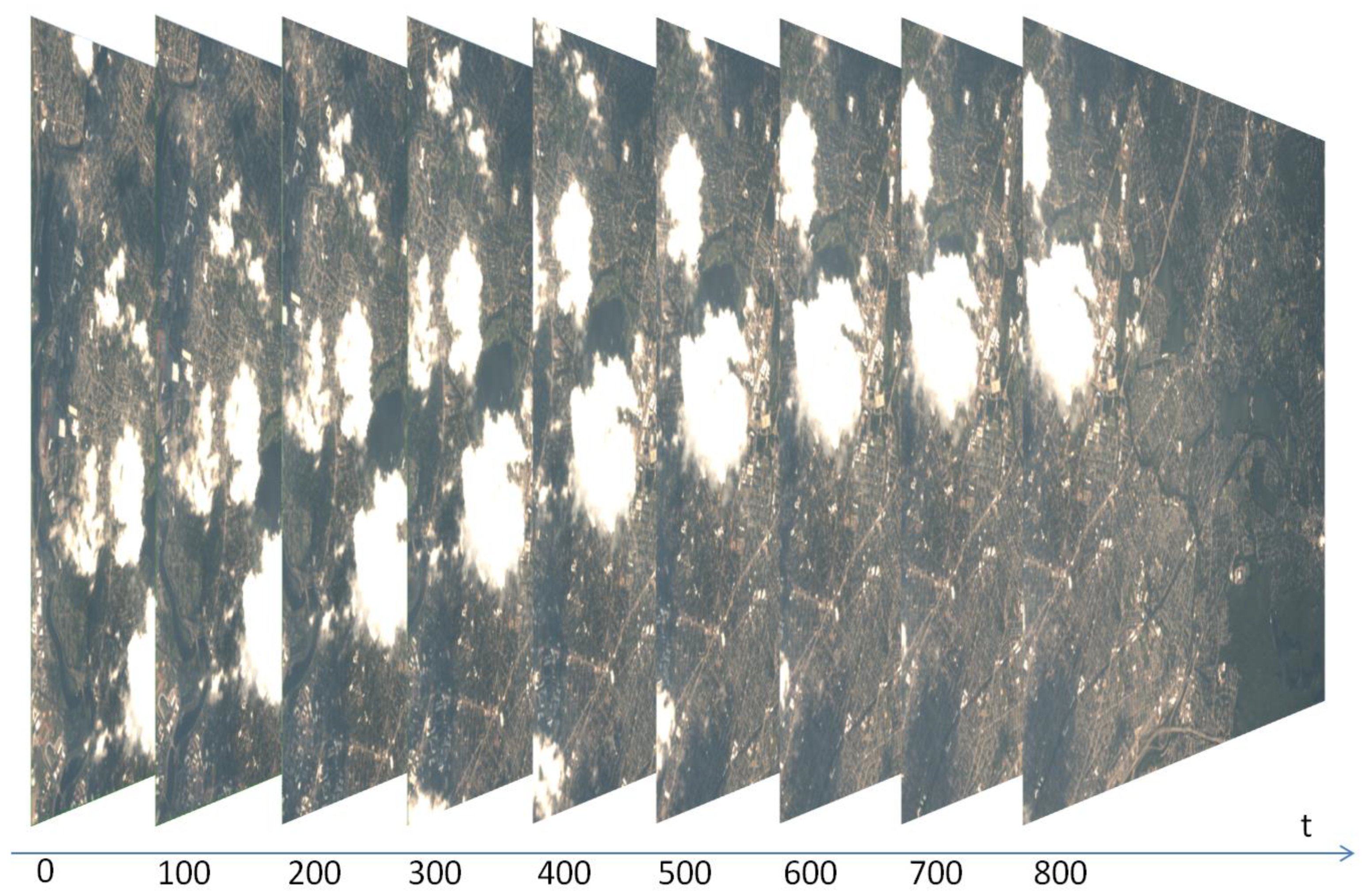
During the joint testing and commissioning of the Luojia3 satellite, application developers carried out various extended applications, including high-precision cloud detection, target detection, change detection, and high magnification compression, based on the architecture of this manuscript, which validates the adaptability and expandability of this architecture.

6. Conclusions

This manuscript proposes a three-level edge computing architecture based on an SoC for low power consumption and expandable on-board processing. Using simulation data, including linear array sensor data and frame array sensor data, to perform experiments on the simulation hardware of the Luojia3 satellite, the results show that the architecture of this manuscript can meet the on-board real-time processing requirements of typical applications. In terms of the support of the base functions provided by the architecture, application developers can make accurate adaptations to their own algorithms to balance requirements and actual conditions and make trade-offs to realize real-time stream computing for various on-board applications. In the future, after the Luojia3 satellite is launched and served, by using the real data obtained from the satellites, more on-board experimental applications based on the architecture of this manuscript will be deployed for further studies through the satellite′s application upload channel. Limited by the capabilities of the Luojia3 satellite, this manuscript mainly focuses on typical optical satellite applications and lacks the exploration of complex application scenarios such as multiple imaging stitching, stereo imaging, and multi-modal data collaborative applications. Further research is worthy of follow-up.

Author Contributions

Conceptualization, Z.Z., S.L. and D.L.; methodology, Z.Z., J.C. and G.X.; software, Z.Z., Z.Q. and J.C.; validation, Z.Z., S.L. and D.L.; writing—original draft preparation, Z.Z. and Z.Q.; writing—review and editing, Z.Z. and Z.Q. All authors have read and agreed to the published version of the manuscript.

Funding

This research was funded by the National Natural Science Foundation of China (No. 61901307), Open Research Fund of State Key Laboratory of Information Engineering in Surveying, Mapping and Remote Sensing, Wuhan University (No. 20E01), Scientific Research Foundation for Doctoral Program of Hubei University of Technology (No. BSQD2020054, No. BSQD2020055).

Data Availability Statement

Not applicable.

Acknowledgments

The authors would like to thank the anonymous reviewers and members of the editorial team for their comments and suggestions.

Conflicts of Interest

The authors declare no conflict of interest. The funders had no role in the design of the study; in the collection, analyses, or interpretation of data; in the writing of the manuscript, or in the decision to publish the results.

References

  1. Li, D.; Shen, X.; Gong, J.; Zhang, J.; Lu, J. On construction of China’s space information network. Geomat. Inf. Sci. Wuhan Univ. 2015, 40, 711–715. [Google Scholar]
  2. Li, D.R. Towards geo-spatial information science in big data era. Acta Geod. Et. Cartogr. Sin. 2016, 45, 379–384. [Google Scholar]
  3. Davis, C.O.; Horan, D.M.; Corson, M.R. On-orbit calibration of the Naval EarthMap Observer (NEMO) coastal ocean imaging spectrometer (COIS). Imaging Spectrom. VI 2000, 4132, 250–259. [Google Scholar]
  4. Visser, S.J.; Dawood, A.S. Real-time natural disasters detection and monitoring from smart earth observation satellite. J. Aerosp. Eng. 2004, 17, 10–19. [Google Scholar] [CrossRef]
  5. Andrew, G.S.; Gabriel, W.; French, M.; Flatley, T.; Villalpando, C.Y. SpaceCubeX: A Framework for Evaluating Hybrid Multi-core CPU/FPGA/DSP Architectures. In Proceedings of the 2017 IEEE Aerospace Conference, Big Sky, MT, USA, 4–11 March 2017; Volume 1–10. [Google Scholar]
  6. Zhou, G.; Zhang, R.; Liu, N.; Huang, J.; Zhou, X. On-Board Ortho-Rectification for Images Based on an FPGA. Remote Sens. 2017, 9, 874. [Google Scholar] [CrossRef] [Green Version]
  7. Huang, J.; Zhou, G. On-Board Detection and Matching of Feature Points. Remote Sens. 2017, 9, 601. [Google Scholar] [CrossRef] [Green Version]
  8. Zhang, N.; Wei, X.; Chen, H.; Liu, W. FPGA Implementation for CNN-Based Optical Remote Sensing Object Detection. Electronics 2021, 10, 282. [Google Scholar] [CrossRef]
  9. Li, L.; Zhang, S.; Wu, J. Efficient Object Detection Framework and Hardware Architecture for Remote Sensing Images. Remote Sens. 2019, 11, 2376. [Google Scholar] [CrossRef] [Green Version]
  10. Zhang, X.; Wei, X.; Sang, Q.; Chen, H.; Xie, Y. An Efficient FPGA-Based Implementation for Quantized Remote Sensing Image Scene Classification Network. Electronics 2020, 9, 1344. [Google Scholar] [CrossRef]
  11. Zhang, N.; Shi, H.; Chen, L.; Lin, T.; Shao, X. A Novel CNN Architecture on FPGA-based SoC for Remote Sensing Image Classification. In Proceedings of the 2019 IEEE International Conference on Signal, Information and Data Processing (ICSIDP), Chongqing, China, 11–13 December 2019. [Google Scholar]
  12. Turner, R. Solar particle events from a risk management perspective. IEEE Trans. Plasma Sci. 2000, 28, 2103–2113. [Google Scholar] [CrossRef]
  13. Petersen, E. Single Event Effects in Aerospace; John and Wiley and Sons: Hoboken, NJ, USA, 2011. [Google Scholar]
  14. Brosser, F.; Milh, E. SEU Mitigation Techniques for Advanced Reprogrammable FPGA in Space. Master’s Thesis, Chalmers University of Technology, Goteborg, Sweden, 2014. [Google Scholar]
  15. Chorasia, J.; Jasani, K.; Shah, A. Realization of various error mitigation techniques for SRAM based FPGA. In Proceedings of the 2017 2nd International Conference for Convergence in Technology (I2CT), Mumbai, India, 7–9 April 2017. [Google Scholar]
  16. Jacobs, A.; Cieslewski, G.; George, A.D.; Gordon-Ross, A.; Lam, H. Reconfigurable Fault Tolerance: A Comprehensive Framework for Reliable and Adaptive FPGA-Based Space Computing. ACM Trans. Reconfigurable Technol. Syst. (TRETS) 2012, 5, 1–30. [Google Scholar] [CrossRef]
  17. Glein, R.; Rittner, F.; Heuberger, A. Adaptive single-event effect mitigation for dependable processing systems based on FPGAs. Microprocess. Microsyst. 2018, 59, 46–56. [Google Scholar] [CrossRef]
  18. Sabogal, S.; George, A.; Wilson, C. Reconfigurable Framework for Environmentally Adaptive Resilience in Hybrid Space Systems. ACM Trans. Reconfigurable Technol. Syst. (TRETS) 2020, 13, 1–32. [Google Scholar] [CrossRef]
  19. George, A.D.; Wilson, C.M. Onboard Processing with Hybrid and Reconfigurable Computing on Small Satellites. Proc. IEEE 2018, 106, 458–470. [Google Scholar] [CrossRef]
  20. Geist, A.; Brewer, C.; Davis, M.; Franconi, N.; Heyward, S.; Wise, T.; Crum, G.; Petrick, D.; Ripley, R.; Wilsonet, C.; et al. SpaceCube v3. 0 NASA next-generation high-performance processor for science applications. In Proceedings of the 33rd Annual AIAA/USU Conference on Small Satellites, Logan, UT, USA, 3–8 August 2019. [Google Scholar]
  21. Müller, S.; Höflinger, K.; Smisek, M.; Gerndt, A. Towards an FDIR Software Fault Tree Library for Onboard Computers. In Proceedings of the 2020 IEEE Aerospace Conference, Big Sky, MT, USA, 7–14 March 2020. [Google Scholar]
  22. Wu, Y.; Gao, L.; Zhang, B.; Yang, B.; Chen, Z. Embedded GPU implementation of anomaly detection for hyperspectral images. High-Perform. Comput. Remote Sens. V 2015, 9646, 66–71. [Google Scholar]
  23. Tang, H.; Li, G.; Zhang, F.; Hu, W.; Li, W. A spaceborne SAR on-board processing simulator using mobile GPU. In Proceedings of the 2016 IEEE International Geoscience and Remote Sensing Symposium (IGARSS), Beijing, China, 10–15 July 2016. [Google Scholar]
  24. Mi, W.; Zhiqi, Z.; Ying, Z.; Zhipeng, D.; Yingying, L. Embedded GPU implementation of sensor correction for on-board real-time stream computing of high-resolution optical satellite imagery. J. Real-Time Image Process. 2018, 13, 565–581. [Google Scholar]
  25. Wang, M.; Zhu, Y.; Jin, S.; Pan, J.; Zhu, Q. Correction of ZY-3 image distortion caused by satellite jitter via virtual steady reimaging using attitude data. ISPRS J. Photogramm. Remote Sens. 2016, 119, 108–123. [Google Scholar] [CrossRef]
  26. Wang, M.; Yang, B.; Hu, F.; Zang, X. On-orbit geometric calibration model and its applications for high-resolution optical satellite imagery. Remote Sens. 2014, 6, 4391–4408. [Google Scholar] [CrossRef] [Green Version]
  27. Wikipedia. Amdahl’s Law. Available online: http://en.wikipedia.org/wiki/Amdahl%27s_law (accessed on 28 March 2016).
  28. Flynn, M.J. Some computer organizations and their effectiveness. IEEE Trans. Comput. 1972, 100, 948–960. [Google Scholar] [CrossRef]
Figure 1. Flowchart of ROI location for linear array sensor data.
Remotesensing 14 03596 g001
Figure 2. Flowchart of ROI location for frame array sensor data.
Remotesensing 14 03596 g002
Figure 3. Concept of on-board hardware architecture.
Remotesensing 14 03596 g003
Figure 4. Multilayer structure of the edge computing architecture.
Remotesensing 14 03596 g004
Figure 5. Flowchart of a typical application using a standard template.
Remotesensing 14 03596 g005
Figure 6. Processing timeline of the application.
Remotesensing 14 03596 g006
Figure 7. Heterogeneous parallel processing strategy.
Remotesensing 14 03596 g007
Figure 8. Panchromatic product of ROI in (a) and detail in (d), Multispectral product of ROI in (b) and detail in (e), Fusion product of ROI in (c) and detail in (f).
Remotesensing 14 03596 g008
Figure 9. Simulation images.
Remotesensing 14 03596 g009
Figure 10. 1080P unstable ROI products in (a) and stable ROI products in (b).
Remotesensing 14 03596 g010
Table 1. Comparison of timeliness between the traditional method and the task-driven method.
Time-ConsumingData Generation 1Step1Step2Step3Step4TotalSpeedup RatioPeak Memory Usage 2
1Traditional method2.7 s6.627 s100.102 s340.014 s227.993 s674.736 s1.05.04 GB
2Task-driven method2.7 s2.034 s1.052 s1.803 s1.204 s6.093 s110.73.16 GB
3Task-driven
GPU parallelism
2.7 s2.046 s0.591 s0.048 s0.078 s2.763 s244.23.17 GB
4Task-driven
heterogeneous parallelism
2.7 s2.012 s0.503 s0.039 s0.065 s2.619 s257.63.17 GB
1: Data generation is calculated by the integral time of the data. This 2.7 s is only used for comparison and is not included in the total. 2: Peak memory usage includes the memory occupation of operating system and application.
Table 2. Comparison of timeliness between the whole scene and the 1080p size.
TypeData Generation *Step1Step2Step3Step4Total
1Whole scene0.067 s0.014 s0.385 s0.044 s1.564 s2.007 s
21080P size0.067 s0.015 s0.014 s0.043 s0.061 s0.133 s
*: The generation time of a single frame equals the inverse of the frequency, which is only used for comparison and is not included in the total.
Table 3. Analysis of the stream computing balance model.
Type V i n / V p t 1 t 2 a b B u f
1Whole scene baseline30.10455 s0 s1310.00 GB
2Whole scene with delay 130.10455 s55 s1161.21 GB
3Whole scene with delay 230.10455 s55 s1220.50 GB
41080P size without delay30.10455 s0 s15.09020.00 GB
51080P size with delay 130.10455 s55 s15.09010.86 GB
61080P size with delay 230.10455 s55 s15.09020.50 GB
Publisher’s Note: MDPI stays neutral with regard to jurisdictional claims in published maps and institutional affiliations.

