
Application of LISA Gravitational Reference Sensor Hardware to Future Intersatellite Geodesy Missions

 ,
,
Abstract
: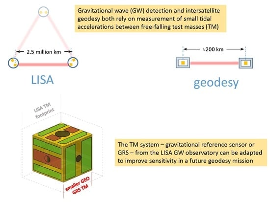
1. Introduction
2. Rationale and Possible Top-Level Requirements for a Geodesy Gravitational Reference Sensor
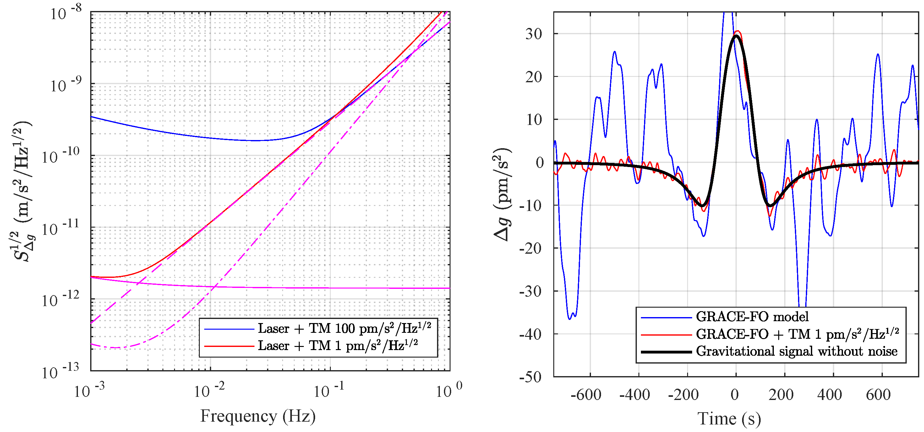
- , the PSD of single TM stray acceleration noise;
- , interferometry displacement noise in a “one-way” link measurement between the two spacecraft (SC);
- , the measurement noise in the local SC-TM displacement measurement;
- , relative noise in the laser frequency.
Top Geodesy GRS Design Requirements
3. Key Design Elements and Performance Characteristics for Geodesy GRS
3.1. Strawman GRS Design
3.2. Capacitive Position Sensing
Sensing Stiffness
3.3. Electrostatic Force Actuation
3.3.1. Actuation Gain Fluctuations and Force Noise
3.3.2. Actuation Stiffness
3.3.3. In-Band Actuation Voltage Noise and Low Frequency Electrostatics
3.4. Brownian Motion from Residual Gas Damping
3.5. Other Key Force Noise Sources
4. Conclusions
Author Contributions
Funding
Data Availability Statement
Conflicts of Interest
Appendix A. Extraction of Differential Gravitational Acceleration in a Simplified Geodesy Measurement with Two-Spacecraft and Reference Test Masses

References
- Amaro-Seaone, P. Laser Interferometer Space Antenna: A proposal in Response to the ESA Call for L3 Mission Concepts. 2017. Available online: http://xxx.lanl.gov/abs/1702.00786 (accessed on 23 February 2017).
- Armano, M.; Audley, H.; Auger, G.; Baird, J.T.; Bassan, M.; Binetruy, P.; Born, M.; Bortoluzzi, D.; Brandt, N.; Caleno, M.; et al. Sub-Femto-g Free Fall for Space-Based Gravitational Wave Observatories: LISA Pathfinder Results. Phys. Rev. Lett. 2016, 116, 231101. [Google Scholar] [CrossRef] [Green Version]
- Armano, M.; Audley, H.; Baird, J.; Binetruy, P.; Born, M.; Bortoluzzi, D.; Castelli, E.; Cavalleri, A.; Cesarini, A.; Cruise, A.M.; et al. Beyond the Required LISA Free-Fall Performance: New LISA Pathfinder Results down to 20 μHz. Phys. Rev. Lett. 2018, 120, 061101. [Google Scholar] [CrossRef] [Green Version]
- Weber, W.J.; Bortoluzzi, D.; Cavalleri, A.; Carbone, L.; Lio, M.D.; Dolesi, R.; Fontana, G.; Hoyle, C.D.; Hueller, M.; Vitale, S. Position sensor for flight testing of LISA drag-free control. In Gravitational-Wave Detection; SPIE: Bellingham, WA, USA, 2003; Volume 4856, pp. 31–42. [Google Scholar]
- Dolesi, R.; Bortoluzzi, D.; Bosetti, P.; Carbone, L.; Cavalleri, A.; Cristofolini, I.; Da Lio, M.; Fontana, G.; Fontanari, V.; Foulon, B.; et al. Gravitational sensor for LISA and its technology demonstration mission. Class. Quantum Grav. 2003, 20, S99. [Google Scholar] [CrossRef]
- Landerer, F.W.; Flechtner, F.M.; Save, H.; Webb, F.H.; Bandikova, T.; Bertiger, W.I.; Bettadpur, S.V.; Byun, S.H.; Dahle, C.; Dobslaw, H.; et al. Extending the Global Mass Change Data Record: GRACE Follow-on Instrument and Science Data Performance. Geophys. Res. Lett. 2020, 47, e2020GL088306. [Google Scholar] [CrossRef]
- Abich, K.; Abramovici, A.; Amparan, B.; Baatzsch, A.; Okihiro, B.B.; Barr, D.C.; Bize, M.P.; Bogan, C.; Braxmaier, C.; Burke, M.J.; et al. In-Orbit Performance of the GRACE Follow-on Laser Ranging Interferometer. Phys. Rev. Lett. 2019, 123, 031101. [Google Scholar] [CrossRef] [Green Version]
- Kang, K.; Bender, P.L. Improved measurements of short-period mass variations with future earth gravity missions. J. Geophys. Res. Solid Earth 2021, 126, e2020JB020720. [Google Scholar] [CrossRef]
- Cristophe, B.; Boulanger, D.; Foulon, B.; Huynh, P.A.; Lebat, V.; Liorzou, F.; Perrot, E. A new generation of ultra-sensitive electrostatic accelerometers for GRACE Follow-on and towards the next generation gravity missions. Acta Astronaut. 2015, 117, 1–7. [Google Scholar] [CrossRef]
- Alvarez, A.D.; Bevilacqua, R.; Hollis, H.; Mueller, G.; Knudston, A.; Patel, U.; Sanjuan, J.; Wass, P.; Conklin, J.W. A Simplified Gravitational Reference Sensor for Satellite Geodesy. 2021. Available online: http://xxx.lanl.gov/abs/2107.08545v4 (accessed on 12 January 2022).
- Massotti, L.; Siemes, C.; March, G.; Haagmans, R.; Silvestrin, P. Next Generation Gravity Mission elements of the Mass Change and Geoscience International Constellation: From orbit selection to instrument and mission design. Remote Sens. 2021, 13, 3935. [Google Scholar] [CrossRef]
- Behzadpour, S.; Mayer-Gürr, T.; Krauss, S. GRACE Follow-On Accelerometer Data Recovery. J. Geophys. Res. 2021, 126, e2020JB021297. [Google Scholar] [CrossRef]
- Weber, W.J. Position sensors for LISA drag-free control. Class. Quantum Grav. 2002, 19, 1751. [Google Scholar] [CrossRef]
- Heinzel, G.; Wand, V.; Danzmann, K. The LTP interferometer and phasemeter. Class. Quantum Grav. 2004, 21, S581. [Google Scholar] [CrossRef] [Green Version]
- Zahnd, B.; Zimmermann, M.; Spörri, R. LISA Pathfinder cage and vent mechanism—development and qualification. In Proceedings of the 15th European Space Mechanisms and Tribology Symposium—ESMATS 2013, Noordwijk, The Netherlands, 25–27 September 2013. [Google Scholar]
- Mäusli, P.A.; Neukom, A.; Romano, R.; Köker, I.; Durrant, S. Development of a Novel Piezo Actuated Release Mechanism. In Proceedings of the 12th European Space Mechanisms and Tribology Symposium—ESMATS, Liverpool, UK, 19–21 September 2007. [Google Scholar]
- Sumner, T.; Araújo, H.; Davidge, D.; Howard, A.; Lee, C.; Rochester, G.; Shaul, D.; Wass, P. Description of charging/discharging processes of the LISA sensors. Class. Quantum Grav. 2004, 21, S597. [Google Scholar] [CrossRef]
- Bortoluzzi, D.; Vignotto, D.; Zambotti, A.; Armano, M.; Audley, H.; Baird, J.; Binetruy, P.; Born, M.; Castelli, E.; Cavalleri, A.; et al. In-flight testing of the injection of the LISA Pathfinder test mass into a geodesic. Adv. Space Res. 2021, 67, 504. [Google Scholar] [CrossRef]
- Armano, M.; Audley, H.; Auger, G.; Baird, J.; Binetruy, P.; Born, M.; Bortoluzzi, D.; Brandt, N.; Bursi, A.; Caleno, M.; et al. Constraints on LISA Pathfinder’s self-gravity: Design requirements, estimates and testing procedures. Class. Quantum Grav. 2016, 33, 235015. [Google Scholar] [CrossRef] [Green Version]
- Armano, M.; Audley, H.; Baird, J.; Binetruy, P.; Born, M.; Bortoluzzi, D.; Castelli, E.; Cavalleri, A.; Cesarini, A.; Cruise, A.M.; et al. Precision charge control for isolated free-falling test masses: LISA pathfinder results. Phys. Rev. D 2018, 98, 062001. [Google Scholar] [CrossRef] [Green Version]
- Kenyon, S.P.; Letson, B.; Clark, M.; Olatunde, T.; Ritten, L.; Schindler, J.; Wass, P.J.; Conklin, J.W.; Barke, S.; Mueller, G.; et al. A Charge Management System for Gravitational Reference Sensors – Design and Instrument Testing. In Proceedings of the IEEE Aerospace Conference, Big Sky, MT, USA, 6–13 March 2021. [Google Scholar] [CrossRef]
- Gan, L.; Mance, D.; Zweifel, P. LTP IS FEE Sensing Channel: Front-End Modeling and Symmetry Adjustment Method. IEEE Sens. J. 2011, 12, 1071. [Google Scholar] [CrossRef]
- Armano, M.; Audley, H.; Auger, G.; Baird, J.; Bassan, M.; Binetruy, P.; Born, M.; Bortoluzzi, D.; Brandt, N.; Caleno, M.; et al. Capacitive sensing of test mass motion with nanometer precision over millimeter-wide sensing gaps for space-borne gravitational reference sensors. Phys. Rev. D 2017, 96, 062004. [Google Scholar] [CrossRef] [Green Version]
- Armano, M.; Audley, H.; Baird, J.; Born, M.; Bortoluzzi, D.; Cardines, N.; Castelli, E.; Cavalleri, A.; Cesarini, A.; Cruise, A.M.; et al. Analysis of the accuracy of actuation electronics in the Laser Interferometer Space Antenna Pathfinder. Rev. Sci. Instrum. 2020, 91, 045003. [Google Scholar] [CrossRef]
- Armano, M.; Audley, H.; Baird, J.; Binetruy, P.; Born, M.; Bortoluzzi, D.; Castelli, E.; Cavalleri, A.; Cesarini, A.; Cruise, A.M.; et al. Calibrating the system dynamics of LISA Pathfinder. Phys. Rev. D 2018, 97, 122002. [Google Scholar] [CrossRef] [Green Version]
- Antonucci, F.; Armano, M.; Audley, H.; Auger, G.; Benedetti, M.; Binetruy, P.; Boatella, C.; Bogenstahl, J.; Bortoluzzi, D.; Bosetti, P.; et al. From laboratory experiments to LISA Pathfinder: Achieving LISA geodesic motion. Class. Quantum Grav. 2011, 28, 094002. [Google Scholar] [CrossRef]
- Armano, M.; Audley, H.; Auger, G.; Baird, J.T.; Binetruy, P.; Born, M.; Bortoluzzi, D.; Brandt, N.; Bursi, A.; Caleno, M.; et al. Charge-Induced Force Noise on Free-Falling Test Masses: Results from LISA Pathfinder. Phys. Rev. Lett. 2017, 118, 171101. [Google Scholar] [CrossRef] [PubMed] [Green Version]
- Speake, C.C. Forces and force gradients due to patch fields and contact-potential differences. Class. Quantum Grav. 1996, 12, A291. [Google Scholar] [CrossRef]
- Antonucci, F.; Cavalleri, A.; Dolesi, R.; Hueller, M.; Nicolodi, D.; Tu, H.B.; Vitale, S.; Weber, W.J. Interaction between Stray Electrostatic Fields and a Charged Free-Falling Test Mass. Phys. Rev. Lett. 2012, 108, 181101. [Google Scholar] [CrossRef] [Green Version]
- Shaul, D.N.A.; Araújo, H.M.; Rochester, G.K.; Sumner, T.J.; Wass, P.J. Evaluation of disturbances due to test mass charging for LISA. Class. Quantum Grav. 2005, 22, S297. [Google Scholar] [CrossRef]
- Sumner, T.; Mueller, G.; Conklin, J.W.; Wass, P.J.; Hollington, D. Charge induced acceleration noise in the LISA gravitational reference sensor. Class. Quantum Grav. 2020, 37, 4. [Google Scholar] [CrossRef] [Green Version]
- Cavalleri, A.; Ciani, G.; Dolesi, R.; Heptonstall, A.; Hueller, M.; Nicolodi, D.; Rowan, S.; Tombolato, D.; Vitale, S.; Wass, P.J.; et al. Increased Brownian Force Noise from Molecular Impacts in a Constrained Volume. Phys. Rev. Lett. 2009, 103, 140601. [Google Scholar] [CrossRef] [Green Version]
- Mehta, P.M.; Walker, A.C.; Sutton, E.K.; Godinez, H.C. New density estimates derived using accelerometers on board the CHAMP and GRACE satellites. Space Weather 2017, 15, 558. [Google Scholar] [CrossRef]
- Armano, M.; Audley, H.; Baird, J.; Binetruy, P.; Born, M.; Bortoluzzi, D.; Castelli, E.; Cavalleri, A.; Cesarini, A.; Cruise, A.M.; et al. Spacecraft and interplanetary contributions to the magnetic environment on-board LISA Pathfinder. Mon. Not. R. Astron. Soc. 2020, 494, 3014. [Google Scholar] [CrossRef]
- Armano, M.; Audley, H.; Baird, J.; Binetruy, P.; Born, M.; Bortoluzzi, D.; Castelli, E.; Cavalleri, A.; Cesarini, A.; Cruise, A.M.; et al. Temperature stability in the sub-milliHertz band with LISA Pathfinder. Mon. Not. R. Astron. Soc. 2019, 486, 3368. [Google Scholar] [CrossRef]
- Carbone, L.; Cavalleri, A.; Ciani, G.; Dolesi, R.; Hueller, M.; Tombolato, D.; Vitale, S.; Weber, W.J. Thermal gradient-induced forces on geodesic reference masses for LISA. Phys. Rev. D 2007, 76, 102003. [Google Scholar] [CrossRef] [Green Version]
- Cavalleri, A.; Ciani, G.; Dolesi, R.; Hueller, M.; Nicolodi, D.; Tombolato, D.; Wass, P.J.; Weber, W.J.; Vitale, S.; Carbone, L. Direct force measurements for testing the LISA Pathfinder gravitational reference sensor. Class. Quantum Grav. 2009, 26, 094012. [Google Scholar] [CrossRef]
- Ciani, G.; Chilton, A.; Apple, S.; Olatunde, T.; Aitken, M.; Mueller, G.; Conklin, J.W. A new torsion pendulum for gravitational reference sensor technology development. Rev. Sci. Instrum. 2017, 88, 064502. [Google Scholar] [CrossRef] [PubMed] [Green Version]
- Bender, P.L. An improved Next Generation Gravity Mission. Remote Sens. 2021, 14, 948. [Google Scholar] [CrossRef]


| LISA | GEO GRS Strawman | |||
|---|---|---|---|---|
| cube sidelength | s | 46 mm | 34 mm | |
| TM mass | M | 1.93 kg | 790 g | Au-Pt |
| TM-EH gap | d | 4/2.9/3.5 mm | 800 m | |
| sensing electrodes | 2 sensing EL per face | gap sensing | ||
| injection electrodes | Y, Z faces | split on Z | ||
| total TM capacitance | pF | pF | ||
| X capacitance | , | pF, 0.3 pF/mm | pF, 5 pF/mm | |
| 100 kHz TM bias | 0.6 V | 0.3 V | ||
| max AC act voltage | V/ V | 50 V | double/single range | |
Publisher’s Note: MDPI stays neutral with regard to jurisdictional claims in published maps and institutional affiliations. |
© 2022 by the authors. Licensee MDPI, Basel, Switzerland. This article is an open access article distributed under the terms and conditions of the Creative Commons Attribution (CC BY) license (https://creativecommons.org/licenses/by/4.0/).
Share and Cite
Weber, W.J.; Bortoluzzi, D.; Bosetti, P.; Consolini, G.; Dolesi, R.; Vitale, S. Application of LISA Gravitational Reference Sensor Hardware to Future Intersatellite Geodesy Missions. Remote Sens. 2022, 14, 3092. https://doi.org/10.3390/rs14133092
Weber WJ, Bortoluzzi D, Bosetti P, Consolini G, Dolesi R, Vitale S. Application of LISA Gravitational Reference Sensor Hardware to Future Intersatellite Geodesy Missions. Remote Sensing. 2022; 14(13):3092. https://doi.org/10.3390/rs14133092
Chicago/Turabian StyleWeber, William Joseph, Daniele Bortoluzzi, Paolo Bosetti, Gabriel Consolini, Rita Dolesi, and Stefano Vitale. 2022. "Application of LISA Gravitational Reference Sensor Hardware to Future Intersatellite Geodesy Missions" Remote Sensing 14, no. 13: 3092. https://doi.org/10.3390/rs14133092