Article

A Truncated Matched Filter Method for Interrupted Sampling Repeater Jamming Suppression Based on Jamming Reconstruction

School of Information and Electronics, Beijing Institute of Technology, Beijing 100081, China
*
Author to whom correspondence should be addressed.
Remote Sens. 2022, 14(1), 97; https://doi.org/10.3390/rs14010097
Submission received: 4 December 2021 / Revised: 21 December 2021 / Accepted: 23 December 2021 / Published: 25 December 2021

Abstract

:
Interrupted sampling repeater jamming (ISRJ) is becoming more widely used in electronic countermeasures (ECM), thanks to the development of digital radio frequency memory (DRFM). Radar electronic counter-countermeasure (ECCM) is much more difficult when the jamming signal is coherent with the emitted signal. Due to the intermittent transmission feature of ISRJ, the energy accumulation of jamming on the matched filter shows a ‘ladder’ characteristic, whereas the real target signal is continuous. As a consequence, the time delay and distribution of the jamming slice can be obtained based on searching the truncated-matched-filter (TMF) matrix. That is composed of pulse compression (PC) results under matched filters with different lengths. Based on the above theory, this paper proposes a truncated matched filter method by the reconstruction of jamming slices to suppress ISRJ of linear frequency modulation (LFM) radars. The numerical simulations indicate the effectiveness of the proposed method and validate the theoretical analysis.

1. Introduction

In recent years, Digital Radio Frequency Memory (DRFM) has been gaining wide acceptance in the field of electronic countermeasure (ECM) and expanding the potential jamming patterns. A great deal of jamming produced by DRFM is coherent with the signal emitted by the victim radar since the jamming process involves intercepting, storing, and retransmitting data from the radar. Jamming techniques, such as interrupted sampling repeater jamming (ISRJ) [1,2], derived from DRFM, can produce a significant amount of false targets which will seriously affect the target detection of victim radars.
The ISRJ is usually composed of signal sampling, storing and repeating which can be achieved by DRFM. The DRFM firstly samples a slice of signal transmitted by the victim radar and then retransmits the slice with different ways. According to the retransmitting scheme, ISRJ can be divided as interrupted sampling and direct repeater jamming (ISDRJ) [1], interrupted sampling and periodic repeater jamming (ISPRJ) [3], and interrupted sampling and cyclic repeater jamming (ISCRJ) [4]. The main difference between ISDRJ and ISPRJ is the retransmitting times of the slice. After sampling from the victim radar, ISDRJ immediately retransmits the slice once, and ISPRJ repeats the slice several times. Unlike ISDRJ and ISRRJ, ISCRJ repeats the current sampling signal and all the previous jamming slices.
Furthermore, many researchers have studied ISRJ’s performance and proposed improved interference tactics [2,5,6,7]. The interrupted-sampling and nonuniform periodic repeater jamming (ISNPRJ) [6] retransmits the sampled signal with different delay and achieves multiple false targets jamming. There is now a new type of ISRJ based on a multi-waveform modulation [7] that compensates for the lack of periodicity of a single type of ISRJ. In order to solve the problem that false targets usually lag behind real targets, a modulation-based ISRJ method [8] is proposed to generate preceding targets.
In contrast, a large number of ECCM technologies against ISRJ have been proposed [9,10,11,12,13,14,15,16,17], which can be roughly categorized into 2 classes: transmitting schemes and echo signal processing schemes.
Transmitting schemes adjust waveform actively to suppress ISRJ. By estimating the ISRJ parameters, the transmitter can generate the optimized waveform orthogonal to jamming signals [18]. The false targets are deduced directly after pulse compression. A time-frequency random coded (TFRC) method [19] in the multi-carrier phased-coded (MCPC) signal is designed to reduce the correlation between radar echo and ISRJ. For ISRJ discontinuity in phase, Hanbali and Kastantin [12] add a linear phase into the emitted signal to counter the approach of active echo cancellation based on ISRJ.
Echo signal processing schemes are another major class of ISRJ suppression method, which can also be subdivided into two categories: filtering methods and signal recovery methods.
The filtering methods are designed to filter out the interference from echo signals. ISRJ usually transmits with much higher energy than the echo signal in order to achieve effective interference. The energy function detection and band-pass filtering (EFDBP) [20] method exploited the energy difference to extract signal without jamming and design filters suppressing side lobes. The energy difference is also be reflected in the time-frequency (TF) domain. Thus, a ’max-TF’ function (MaxTF) [21] was proposed to design a filter in the TF domain directly to suppress jamming signals. The Sliding-Truncation Matched Filter (STMF) method [22] analyzed the difference between the real target signals and jamming signals in the TF domain. By truncating and sliding the matched filter, the jamming parameters can be extracted and estimated. Information entropy is another method to distinguish real target signal and jamming signal. Ref. [20] utilized the difference in information entropy between the real target signal and the interfering signal after singular value decomposition (SVD) to design a band-pass filter.
Alternatively, a lot of research studies today have attempted to employ compressed sensing (CS) to recover the real target signal directly from the jammed signal [23,24,25]. The real target signal in time domain extracted by the energy function can be utilized as a kind of compressed data [24]. LFM signals are sparse in the spectrum after differential beat processing, so a linear relationship between the echo signal and the spectrum can be established. The real target signal was recovered with some common sparse recovery algorithms, such as orthogonal matching pursuit (OMP). Ref. [26] considered the noise effect and improved the interference rejection performance of the compressed sensing algorithm at low signal-to-noise ratio by introducing Bayesian compress sensing (BCS). It has been suggested that some researchers utilize fractional Fourier transforms (FRFT) to find methods to suppress jamming for the aggregation characteristic of LFM signals in the fractional domain [27,28,29].
Transmitting schemes can achieve better interference suppression due to the joint transmitting waveform design. However, it is not possible to design waveforms for only one type of interference in practical situations. It makes more sense to suppress interference by echo signal processing. Nevertheless, the conventional echo signal processing methods have poor interference suppression at low signal-to-noise ratios (SNR) because they usually utilized only part of the unjammed echo signal.
This study creatively proposes a truncated matched filter method based on the reconstruction of jamming slices to improve the ISRJ suppression performance. This method utilizes information from jamming signals, whose amplitude is higher than that of the real target signal. This allows for more accurate reconstruction and is suitable for low SNR regimes. The two main factors used to reconstruct the jamming slices are the delay time of jamming signal and the jamming slice segment corresponding to that. The method constructs a search matrix composed of pulse compression results under the matched filters with different lengths. At the peak position of the PC result using the full-length filter, the ladder characteristic in the filter length domain is effective to extract the jamming slice. In addition, the peak position can be thought as the delay time of the jamming signal corresponding to the reference signal. The method has improved the suppression performance and keep the jamming-free signal as much as possible. It shows a great efficiency under high jamming-to-signal ratios (JSR) and low SNR circumstances.
The remainder of this paper is arranged as follows. In Section 2, the model of radar signal and the mechanism of ISRJ are described. In Section 3, the truncated matched filter method is detailed as instructed, including building truncated matched filter matrix, extracting jamming slice, and reconstructing jamming slices. In Section 4, simulation results are presented to validate the proposed method. Finally, the conclusions are drawn in Section 5.

2. Signal Model

2.1. Signal Model of LFM Radar

The normalized LFM continuous signal in a transmitting cycle can be expressed as:
s ( t ) = e j 2 π ( f 0 t + 0.5 k t 2 ) , t [ 0 , T ] ,
where f 0 is the carrier frequency; T is the period of the emitted signal; k = B / T represents the frequency modulation slope, of which B stands for the bandwidth. The carrier frequency of the signal can be neglected since it doesn’t affect the deductions in this study. So, it can be simplified as:
s t = e j π k t 2 , t 0 , T .
The echo signal of scattering point model is formulated below [29].
x t = i = 1 K A i s ( t τ i ) + n ( t ) = i = 1 K A i e j π k t τ i 2 + n ( t ) ,
where A i and τ i represent the amplitude and time delay of the i-th scattering point, respectively; K is the number of the scattering points. Without loss of generality, it is common to assume the target as a single scattering point model [28]. Thus, the echo signal of the target can be expressed as follows:
x t = A s e j π ( t τ s ) 2 + n ( t ) , t 0 , T ,
where A s is the amplitude of the target; τ s is the time delay. τ s = 2 R s / c , where c represents the speed of light, and R s is the distance between the target and the radar.

2.2. Mechanism of ISRJ

Figure 1 shows the mechanism of ISRJ. Since the three types of ISRJ are all based on retransmitting the sampling slice, ISRJ can be thought as a linear combination of several jamming slices. For this paper, firstly, we build the model of a slice, which can be expressed as follows.
s J t = A J rect t u T I e j π k ( t u ) 2 ,
rect ( t ) = 1 , 0 t 1 0 , otherwise
where A J is the amplitude of the jamming signal; rect ( t ) is a standard rectangular window function with pulse width 1 and initial location 0; u and T I are the delay and width of the jamming slice; u is the delay of the jamming slice relative to the initial signal emitted by the victim radar.
Construct the matched filter for the transmitted signal, which is expressed as:
h t = s * t = e j π k t 2 , t 0 , T ,
where ∗ represents conjugation operator. Thus, the output of the match filter for a jamming slice can be written as:
S MF t = s J t h t = rect v u T I e j π k ( v u ) 2 · e j π k ( t v ) 2 d v = A J e j π k u 2 t 2 · rect v u T I e j 2 π k u t v d v ,
where ⊗ stands for the convolution operator.
According to the Fourier transform pairs:
rect t τ T I S a ω τ 2 , f t u F ω e j ω u ,
where S a ( x ) = sin ( x ) / x , the integral part of the formula can be thought as the Fourier transform of the rectangular window function rect [ ( v u ) / T I ] , when ω is set to 2 π k ( u t ) Thus, the last part of (8) can be written as:   
rect v u T I e j 2 π k u t v d v = T I S a 2 π k u t 2 T I e j 2 π k u t u .
Therefore, the output of the match filter for a jamming slice can be summarized as:
S MF t = A J T I S a 2 π k u t 2 T I · e j π k u 2 t 2 e j 2 π k u t u .
It is obvious that the peaks will appear if each part of the formula gets the maximum value and that will be achieved when t is set to u .

3. Truncated Matched Filter for ISRJ Suppression

Based on the above signal model, this paper proposes a truncated matched filter method to suppress ISRJ interference. Firstly, we generate a series of matched filters whose length change from 0 to the full length L. The full length means the length of the matched filter is the same as the received signal. After that, we can get a two-dimensional matrix composed of the pulse compression results under truncated matched filters with different lengths of window. The m × k matrix R is named as TMF matrix, where m represents the delay time, and k is the window length. By searching the rising edge in the window length dimension of the peak position in the delay dimension, the position and width of the jamming slice can be obtained and used to restructure the jamming slice. At last, subtract the jamming signal from the received signal to realize ISRJ Suppression.

3.1. Truncated Matched Filter

In the first place, we truncate the full-length matched filter into different lengths to get the truncated matched filter:
h t , T w = rect t T w · e j π k t 2 .
The output of the matched filter, which is also called a pulse compression (PC) result, is formulated as follows:
S TMF t , T w = s J t h t , T w = A J e j π k u 2 t 2 · rect v u T I · rect t v T w e j 2 π k u t v d v .
Since the product result of two rectangular window functions is still a rectangular window function, combine them as:
g v , T w = rect v u T I rect t v T w = rect v u ^ T 0 ,
where u ^ is the delay of the new rectangular window function; T 0 is the overlapping time period of the matched filter and the jamming slice, which is corresponding to u and T I . Based on the derivation in Section 2, we can set ω = 2 π k u t and make use of the Fourier transform pairs to get the result:   
S T M F t , T w = A J T 0 S a 2 π k u t 2 T 0 · e j π k u 2 t 2 e j 2 π k u t u ^ .
Obviously, the PC result of a jamming slice will get the maximum value when t = u , and the amplitude of the peak position can be expressed as:
S T M F u , T w = A J T 0 .
Considering that the delay of the truncated matched filter is the same as the transmitted signal, the overlapping time T 0 is just determined by the length of the filter. So, give the formula of the maximum value as a piecewise function:
S TMF ( u ) = 0 , t [ 0 , τ 0 ] A J ( T w τ 0 ) , t ( τ 0 , τ 0 + T I ] , A J T w , t ( τ 0 + T I , T ]
where τ 0 represents the time when the filter and the jamming slice start overlapping. In extreme cases, the maximum value will be simplified into two parts when τ 0 = 0 or τ 0 + T I = T . It can be concluded from the Formula (17) that the maximum value versus the length presents a ladder characteristic. There is no overlapping part between the filter and the jamming slice, and the PC result equals to 0 until the length of the filter reaches the starting time of the jamming slice. The PC result will increase as the overlapping part increases. When the jamming slice is completely covered by the matched filter, it will achieve the maximum value. After that, the increasing length will not influence that, and the PC result will maintain the value without changing.
The PC result between the matched filter and the target signal can be written as:
S s t = x t h t , T w = A s e j π k v τ s · rect t v T w e j π k t v 2 d v = A s e j π k τ s 2 t 2 · rect t v T w e j 2 π k τ s t v d v = A s T w S a 2 π k τ s t 2 T w · e j π k τ s 2 t 2 e j 2 π k τ s t v .
Similarly, the amplitude of the peak position can be formulated as:
S s τ s = A s T w .
It is different with the jamming slice that the maximum value of the PC result generated by the target signal shows a linear increase relationship with the length of the matched filter. In contrast, the PC result of the jamming slice contains at least one period with constant value, which is called as a ladder characteristic. Despite the fact that a lot of peaks will be detected when the echo signal is jammed by ISRJ, we take advantage of this to distinguish whether the peak is caused by the jamming slice or the real target signal.
The TF representation and PC results under different matched filters are depicted in Figure 2. For a better view of the TF features of the target signals and jamming signals, we use the ISDRJ as an example, and related parameters are set as Table 1. Figure 2a is the TF energy distribution images. From Figure 2b, the PC result of jamming signal is far higher than the real target signal, and it is difficult to distinguish them. However, we can find in Figure 2c that the interrupted emitting of ISDRJ makes the PC results show the ladder characteristic, along with the change of the length of matched filter. Figure 2d is the TMF matrix.

3.2. Extraction and Reconstruction of Jamming Slice

The ‘ladder’ characteristic and the TMF matrix facilitate the extraction and reconstruction of jamming slices. Firstly, the PC result filtered by the full-length matched filter will be detected by Constant False Alarm Rate (CFAR) detectors:
P max t 0 = Γ { S TMF t , T } ,
where t 0 = { t 1 , t 2 , , t n } represents the time of n targets detected; Γ { · } denotes the CFAR detection operator. Noise and the side lobe of the jamming slice will make the edge of the rising part jitter, which will result in the inaccuracy of the edge determination. Therefore, some centroid estimation methods can be applied to the PC results based on Reference [30]. So that we can get the all targets, including false targets and the real target, for the i-th peak, the PC results can be extracted, along with the filter length domain, to get the max-peak function P m a x T w
P i , max T w = S TMF t i , T w .
The steps of extracting jamming slice are described below.
Step 1: Differentiate the max-peak function P i , max T w and get P i , max T w .
Step 2: Determine a threshold γ 0 to extract the jamming slice function c T w . Since PC result jammed by ISRJ will show the ladder characteristic which is demonstrated in Section 3.1, the differential of the max-peak function can extract the rising part. According to (16) and (17), the threshold can be set as:
γ 0 = max P i , max T w T ,
where T can be replaced as the number of sample points in the discrete form. Then, c T w can be written as
c ( T w ) = 1 , P i , max T w > γ 0 , 0 , P i , max T w γ 0 ,
where c T w equals to 1 means the end of the filter coincides with the jamming slice. c T w represents the jamming slice that produces the i-th peak in P m a x t 0 . Therefore, we can rewrite c T w as
c ( t ) = 1 , P i , max T w > γ 0 , 0 , P i , max T w γ 0 ,
which represents the jamming segments in terms of the peak position. The jamming slice can be divided into multiple continuous segments.
Step 3: Assume that the signal sequence detected at the radar receiver is x = x 1 , x 2 , , x n T and the transmitting signal sequence is s = s 1 , s 2 , , s n T . Then, select the p-th piece of continuous jamming slice j p = s l , s l + 1 , , s l + Q T , where l and Q are the number of starting point and the length of jamming slice, respectively. M points around the start and end position of each segment also need to be searched in order to reduce the influence of noise. Thus, the expanded jamming slice can be expressed as:
j p = [ s l M + 1 , s l M , , s l , s l + 1 , , s l + Q , s l + Q + 1 , , s l + Q + M 1 ] T .
If i in l M + 1 , l M , , l + Q + M 1 exceeds the length of the local reference code signal, set i = i N . If i 0 , set i = i + N . In addition, the p-th piece of echo signal is formulated as:
x p = [ x l M + 1 , x l M , , x l , s l + 1 , , x l + Q , x l + Q + 1 , , x l + Q + M 1 ] T .
Construct the searching matrix K p as:
K p = [ k p 1 , 1 , k p 2 , 1 , , k p M , 1 , k p 1 , 2 , k p 2 , 2 , , k p M , 2 , , k p M , M ] T
where
k p ( i , q ) = 1 Q + 2 M i q + 2 [ 0 1 × i 1 , x l + i 1 , x l + i , , x l + Q + 2 M q , 0 1 × q 1 ] T .
i = 1 , 2 , , M and q = 1 , 2 , , M . 0 is the zero matrix.
Step 4: The reconstructed signal most similar to the jamming slice will be picked out by the minimum remaining energy criterion. For each tow in the searching matrix K p , caculate the remaining energy criterion R p i , q as follows:
R p i , q = x p k p ( i , q ) x p | | k p ( i , q ) | | 2 k p ( i , q ) 2 .
Select the row with the minimum R p i , q and the reconstructed jamming slice j c can be expressed as:
j c = k p ( i min , q min ) x p | | k p ( i min , q min ) | | 2 k p ( i min , q min ) .
Step 5: Repeat step 3 and 4 until all the jamming slices have been reconstructed.
The specific algorithm is described in Algorithm 1.
Algorithm 1: Truncated Matched Filter Method for jamming slice extraction.
Input: The max-peak function P i , max T w , the transmitting cycle time T, echo signal s ( t )
Output: The reconstructed jamming signal j ( t )
  • Differentiate P i , max T w and obtain P i , max T w ;
  • Determine γ 0 according to Equation (22) and obtain c ( t ) by Equations (23) and (24);
  • Calculate the searching matrix K p according to Equation (27).
  • Calculate and select the minimum remaining energy criterion. Reconstruct the jamming slice with Equation (30).
  • If all the jamming slices are reconstructed, stop the reconstruction and output the signal without jamming; otherwise back to 3.
To summarize, the jamming suppression method is composed of four stages, as shown in Figure 3. Firstly, we extract signals by the truncated matched filters with variable lengths from the received signal and get a two-dimensional matrix. Secondly, jamming slice and parameters are detected from the matrix. Then, we can reconstruct the jamming slice with the parameters. Finally, the interference suppressed signal can be obtained by subtracting the jamming slices from the jammed signal.

4. Simulation

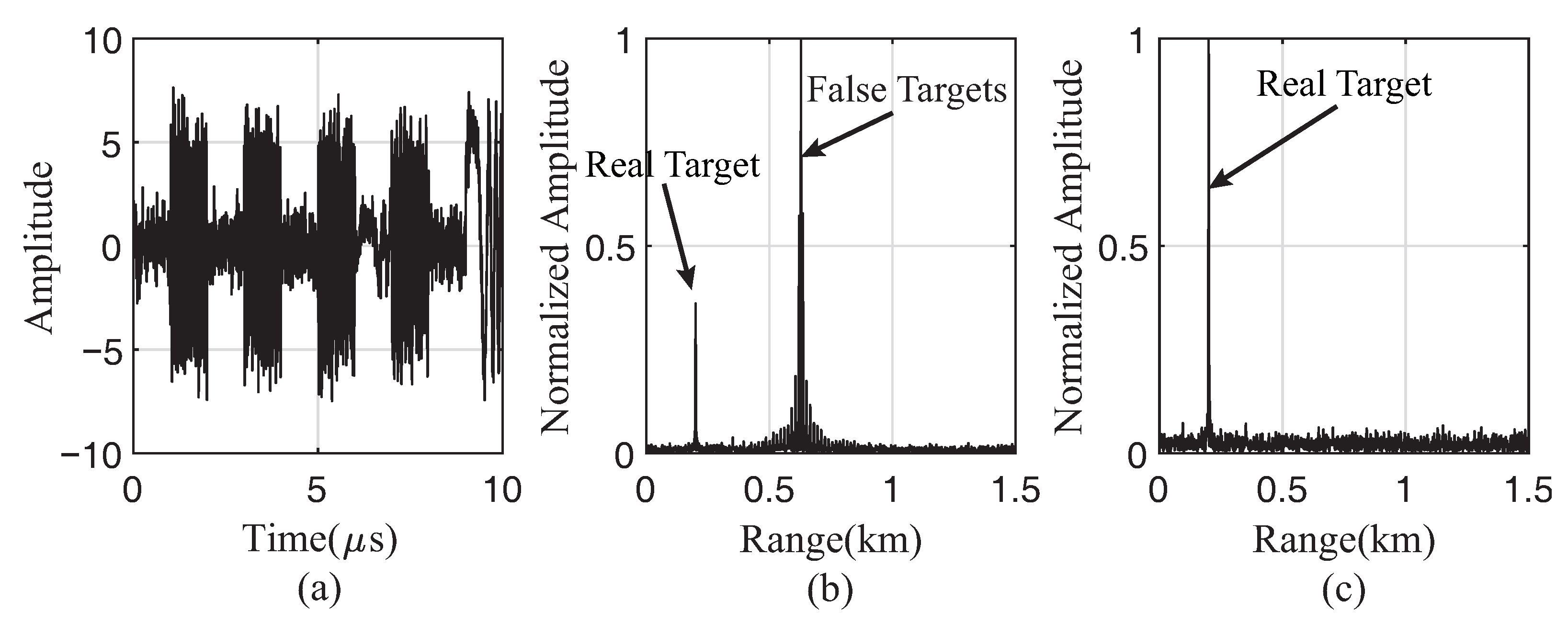
4.1. Interference Suppression Based on TMF

As shown in (2), the transmitting signal is assumed as LFM signal. Based on the jamming model in Section 2, related parameters are set as Table 1.
The echo signal in time domain and the pulse compression results before and after suppression are all shown in Figure 4, Figure 5 and Figure 6. As demonstrated in the figures, the three jamming types show different features in the PC results. ISDRJ retransmits the sampled signal at once, making the same delay of each repeat period. As a result, there will be only one master false target with high amplitude. ISPRJ is similar with ISDRJ. Since it will repeat the sampled signal with several times, the number of master false targets equals to the repeating times in a repeating period. Unlike ISDRJ and ISPRJ, ISCRJ repeats the current jamming slice and the previous jamming slice. The current jamming slice in each repeating period generates a false target at the same position. Under that circumstance, the PC result of ISCRJ is composed of a main false target with high amplitude and numerous multiple secondary false targets. All the three pulse compression results after TMF interference suppression are almost entirely composed of the real target without any false one which proves the effectiveness of this method.

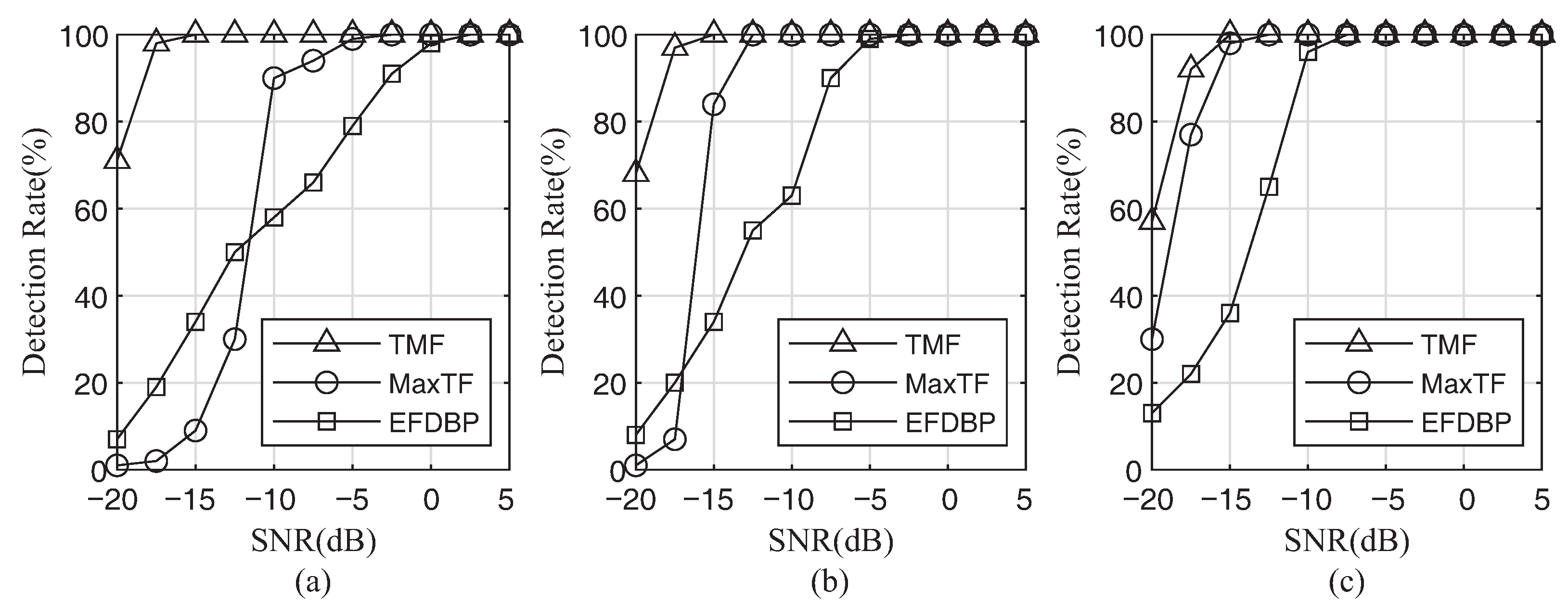
4.2. Monte-Carlo Simulations and Results

We utilized the probability of target detection as evaluation criteria.
The probability of target detection is the rate of radar detecting targets in PC results, which can be calculated as
P d = N d / N total ,
where P d represents the probability of target detection; N total is the total number of PC results, and N d targets are detected by radar.
Figure 7, Figure 8 and Figure 9 are the probability of target detection curve after the jamming suppression with three jamming types and three jamming suppression methods, where 1000 times of Monte Carlo simulation are performed on each SNR and JSR. From the probability of target detection curve, it can be seen that:
(i)
Under the three jamming suppression methods, the probability of target detection will improve with the increase of SNR and JSR. The reason is that, when SNR and JSR rise, the distinction between jamming and true target signals becomes increasingly clear, which makes it easier to extract interference-free segments for MaxTF and EFDBP methods. In the TMF method, higher SNR and JSR mean higher jamming-noise ratio (JNR) and better recovery of jamming signals, which improves interference suppression.
(ii)
The TMF method shows better performance in lower SNR and JSR compared with other methods. The other two methods rely on the extraction of interference-free segments, whereas their extraction performance in the low SNR and JSR regimes is poor. In addition, the TMF method is to recover jamming signals directly. When the SNR and JSR are low, the JNR is still high enough to ensure the recovery of jamming signals, resulting in a greater interference suppression effect.
(iii)
For the same jamming type, the performance of the three jamming suppression methods increases with the SNR raising. For the same jamming suppression method, the performance under the three jamming types show the similar improvement characteristic. The other two methods are not sensitive to jamming types because they rely on identifying interference-free segments. The TMF method provides great interference suppression for them because it recovers each independent jamming slice, and all three types of jamming are based on the combination of multiple jamming slices.

5. Conclusions

ISRJ has gradually become the most significant factor on detecting, tracking, and recognizing targets of radar. Many ECCM approaches have been proposed against ISRJ. However, they show poor performance in low SNR regimes, whether in detection rate and jamming-free signal segments extraction. Besides, most ECCM techniques need to detect or recognize whether the jamming exists, and they can only be employed in the presence of ISRJ.
Based on the study of ISRJ principle, this paper proposed a TMF-based ISRJ interference suppression method to surmount these shortcomings. It automatically and accurately extracts and reconstructs jamming slices, which can greatly keep the signal of real targets. By subtracting the jamming slices from the jammed signal, we can get the integral jamming-free signal, almost without information loss. Mathematical derivation and simulations verified the effectiveness of the method. This method performs better in detection rate and the ability of interference suppression, especially in low SNR regimes. However, the proposed method is computationally intensive because it consumes a lot of resources in constructing the search matrix. Further research studies will be carried out on reducing the computation and working in a more complex real environment.

Author Contributions

Conceptualization, M.G.; Formal analysis, L.L.; Investigation, L.L.; Methodology, L.L.; Validation, L.L.; Writing—original draft, L.L.; Writing—review & editing, M.G. All authors have read and agreed to the published version of the manuscript.

Funding

This work was supported by the National Natural Science Foundation of China under Grant 62071041 and 61701554, Shanghai Aerospace and Technology Innovation Foundation, China, under Grant SAST-2020078.

Institutional Review Board Statement

Not applicable.

Informed Consent Statement

Not applicable.

Data Availability Statement

The data presented in this study are available on request from the corresponding author.

Conflicts of Interest

The authors declare no conflict of interest.

References

  1. Wang, X.; Liu, J.; Zhang, W.; Fu, Q.; Liu, Z.; Xie, X. Mathematic principles of interrupted-sampling repeater jamming (ISRJ). Sci. China Ser. F Inf. Sci. 2007, 50, 113–123. [Google Scholar] [CrossRef]
  2. Feng, D.; Xu, L.; Pan, X.; Wang, X. Jamming wideband radar using interrupted-sampling repeater. IEEE Trans. Aerosp. Electron. Syst. 2017, 53, 1341–1354. [Google Scholar] [CrossRef]
  3. Liu, Z.; Wang, X.S.; Liu, J.C.; Wang, G.; Xiao, S. Jamming technique of interrupted-sampling and periodic repeater based on digital radio frequency memory. Acta Armamentarii 2008, 29, 405–410. [Google Scholar]
  4. Zhong, L. Jamming Technique for Countering LFM Pulse Compression Radar Based on Digital Radio Frequency Memory. Ph.D. Dissertation, National University of Defense Technology, Changsha, China, 2006. [Google Scholar]
  5. Li, H.; Zhao, G.; Yang, Y.; Gao, H. The performance analysis of multi-false target jamming of part copying Radar pulse. Electron. Inf. Warf. Technol. 2010, 25, 39–44. [Google Scholar]
  6. Yang-rui, Z.; Yun-jie, L.; Man-ling, L.; Mei-guo, G.; Xiong-jun, F. Suppress Jamming Technique of Multiple False Targets on Interrupted-Sampling and Non-Uniform Periodic Repeater. Acta Electron. Sin. 2016, 44, 46–53. [Google Scholar] [CrossRef]
  7. Ping, Z.; Qingsheng, Z.; Yanbin, L.; Nan, H.; Wenqing, X. Intermittent Sampling Repeater Jamming Technique Based on Multi-waveform Modulation. Mod. Radar 2020, 42, 77–83. [Google Scholar] [CrossRef]
  8. Li, C.Z.; Su, W.M.; Gu, H.; Ma, C.; Chen, J.L. Improved interrupted sampling repeater jamming based on DRFM. In Proceedings of the 2014 IEEE International Conference on Signal Processing, Communications and Computing (ICSPCC), Guilin, China, 5–8 August 2014; pp. 254–257. [Google Scholar]
  9. Jianzhong, Z.; Heqiang, M.; Shuliang, W.; Yanbing, L.; Hongwei, G. Anti-Intermittent Sampling Repeater Jamming Method Based on LFM Segmented Pulse Compression. J. Electron. Inf. Technol. 2019, 41, 1712–1720. [Google Scholar] [CrossRef]
  10. Zhou, C.; Liu, Q.; Chen, X. Parameter estimation and suppression for DRFM-based interrupted sampling repeater jammer. IET Radar Sonar Navig. 2018, 12, 56–63. [Google Scholar] [CrossRef]
  11. Xiong, W.; Zhang, G.; Liu, W. Efficient filter design against interrupted sampling repeater jamming for wideband radar. EURASIP J. Adv. Signal Process. 2017, 2017, 1–12. [Google Scholar] [CrossRef] [Green Version]
  12. Hanbali, S.B.S.; Kastantin, R. Technique to counter active echo cancellation of self-protection ISRJ. Electron. Lett. 2017, 53, 680–681. [Google Scholar] [CrossRef]
  13. Zhou, K.; Li, D.; Quan, S.; Liu, T.; Su, Y.; He, F. SAR Waveform and Mismatched Filter Design for Countering Interrupted-Sampling Repeater Jamming. IEEE Trans. Geosci. Remote Sens. 2021, 1–14. [Google Scholar] [CrossRef]
  14. Yu, M.; Dong, S.; Duan, X.; Liu, S. A novel interference suppression method for interrupted sampling repeater jamming based on singular spectrum entropy function. Sensors 2019, 19, 136. [Google Scholar] [CrossRef] [PubMed] [Green Version]
  15. Zhou, K.; Li, D.; Su, Y.; Liu, T. Joint design of transmit waveform and mismatch filter in the presence of interrupted sampling repeater jamming. IEEE Signal Process. Lett. 2020, 27, 1610–1614. [Google Scholar] [CrossRef]
  16. Hanbali, S.B.S. Technique to counter improved active echo cancellation based on ISRJ with frequency shifting. IEEE Sens. D 2019, 19, 9194–9199. [Google Scholar] [CrossRef]
  17. Zhang, J.; Zhou, C. Interrupted Sampling Repeater Jamming Suppression Method based on Hybrid Modulated Radar Signal. In Proceedings of the 2019 IEEE International Conference on Signal, Information and Data Processing (ICSIDP), Chongqing, China, 11–13 December 2019; pp. 1–4. [Google Scholar]
  18. Zhou, C.; Liu, F.; Liu, Q. An adaptive transmitting scheme for interrupted sampling repeater jamming suppression. Sensors 2017, 17, 2480. [Google Scholar] [CrossRef] [Green Version]
  19. Li, J.; Luo, X.; Duan, X.; Wang, W.; Ou, J. A Novel Radar Waveform Design for Anti-Interrupted Sampling Repeater Jamming via Time-Frequency Random Coded Method. Prog. Electromagn. Res. M 2020, 98, 89–99. [Google Scholar] [CrossRef]
  20. Mu-yao, Y.; Sheng-bo, D.; Xiang-yu, D. An Interference Suppression Algorithm of Multiple False Targets for Pulse Doppler Radar. J. Signal Process. 2017, 33, 1578–1584. [Google Scholar] [CrossRef]
  21. Chen, J.; Wu, W.; Xu, S.; Chen, Z.; Zou, J. Band pass filter design against interrupted-sampling repeater jamming based on time-frequency analysis. IET Radar Sonar Navig. 2019, 13, 1646–1654. [Google Scholar] [CrossRef]
  22. Chao, Z.; Quan-hua, L.; Tao, Z. Research on DRFM Repeater Jamming Recognition. J. Signal Process. 2017, 33, 911–917. [Google Scholar] [CrossRef]
  23. Wei, Y.; Lu, Z.; Yuan, G.; Fang, Z.; Huang, Y. Sparsity adaptive matching pursuit detection algorithm based on compressed sensing for radar signals. Sensors 2017, 17, 1120. [Google Scholar] [CrossRef]
  24. Hui, Y.; Chunyang, W.; Lei, A.; Xin, L. ECCM scheme against interrupted-sampling repeater jamming based on compressed sensing signal reconstruction. Syst. Eng. Electron. 2018, 40, 717–725. [Google Scholar] [CrossRef]
  25. Zhao, Y.; Gini, F.; Greco, M.; Tang, B. Radar ECCM based on phase-aid distributed compressive sensing. Signal Image Video Process. 2018, 12, 1497–1504. [Google Scholar] [CrossRef]
  26. Huan, S.; Dai, G.; Luo, G.; Ai, S. Bayesian compress sensing based countermeasure scheme against the interrupted sampling repeater jamming. Sensors 2019, 19, 3279. [Google Scholar] [CrossRef] [Green Version]
  27. Yang, Z.; Chaoxuan, S.; Zhuangzhi, H.; Ning, H.; Hui, X. Fractional Fourier Transform and Compressed Sensing Adaptive Countering Smeared Spectrum Jamming. J. Electron. Inf. Technol. 2019, 41, 1047–1054. [Google Scholar] [CrossRef]
  28. Zhang, L.; Wang, G.; Zhang, X.; Li, S.; Xin, T. Interrupted-sampling repeater jamming adaptive suppression algorithm based on fractional dictionary. Syst. Eng. Electron. 2020, 42, 1439–1448. [Google Scholar] [CrossRef]
  29. Fang, B.; Huang, G.; Gao, J. Sub-Nyquist sampling and reconstruction model of LFM signals based on blind compressed sensing in FRFT domain. Circuits Syst. Signal Process. 2015, 34, 419–439. [Google Scholar] [CrossRef]
  30. Tuncay, P.; Kartal, M. A new method for Doppler centroid estimation based on block processing. In Proceedings of the 2013 6th IEEE International Conference on Recent Advances in Space Technologies (RAST), Istanbul, Turkey, 12–14 June 2013; pp. 417–420. [Google Scholar]
Figure 1. Mechanism of ISRJ.
Remotesensing 14 00097 g001
Figure 2. Comparison of different characters between real target signal and jamming signal. (a) The TF analysis; (b) the pulse compression results filtered with the full-length matched filter; (c) the pulse compression results versus the lengths of matched filters; (d) the TMF matrix.
Remotesensing 14 00097 g002
Figure 3. Flow chart of interference suppression.
Remotesensing 14 00097 g003
Figure 4. Simulation results of TMF for ISDRJ. (a) The echo signal with ISDRJ; (b) pulse compression of the echo signal; (c) pulse compression of echo signal after TMF.
Remotesensing 14 00097 g004
Figure 5. Simulation results of TMF for ISPRJ. (a) The echo signal with ISPRJ; (b) pulse compression of the echo signal; (c) pulse compression of echo signal after TMF.
Remotesensing 14 00097 g005
Figure 6. Simulation results of TMF for ISCRJ. (a) The echo signal with ISCRJ; (b) pulse compression of the echo signal; (c) pulse compression of echo signal after TMF.
Remotesensing 14 00097 g006
Figure 7. The probability of target detection with different jamming suppression methods for ISDRJ. (a) JSR = 5 dB; (b) JSR = 10 dB; (c) JSR = 15 dB.
Remotesensing 14 00097 g007
Figure 8. The probability of target detection with different jamming suppression methods for ISPRJ. (a) JSR = 5 dB; (b) JSR = 10 dB; (c) JSR = 15 dB.
Remotesensing 14 00097 g008
Figure 9. The probability of target detection with different jamming suppression methods for ISCRJ. (a) JSR = 5 dB; (b) JSR = 10 dB; (c) JSR = 15 dB.
Remotesensing 14 00097 g009
Table 1. Simulation parameters.
ParameterSymbolUnitValue
Signal-to-noise ratio S N R dB0
Jamming-to-signal ratio J S R dB15
Radar signal cycleT μ s10
Radar signal band widthBMHz100
Radar receiver complex sampling frequency f s MHz150
Target location R 0 m200
Main false target location R J m678
ISRJsampling pulse width T I μ s1
Pulse repetition interval of ISPRJ T ISPRJ μ s2
Slice number of ISPRJ N ISPRJ 3
Publisher’s Note: MDPI stays neutral with regard to jurisdictional claims in published maps and institutional affiliations.

