1. Introduction
The highly elliptical orbit is mainly used in space exploration, communication and remote sensing engineering practice that enables a good observation of coverage characteristics. Based on the unique advantages of highly elliptical orbits, it has been gradually introduced into spaceborne synthetic aperture radar (SAR) in recent years. Due to its high eccentricity, the highly elliptical orbit SAR (HEO SAR) has the observation characteristics of both low earth orbit (LEO) [
1] SAR and geosynchronous earth orbit (GEO) SAR [
2,
3,
4], which could meet the observation requirements of different latitudes by setting perigee and apogee positions [
5]. The eccentricity of the highly elliptical orbit is generally greater than 0.6, its perigee height is usually 500 km, and the apogee height is up to 50,000 km. According to Kepler’s law, the satellite moves slowly at apogee so that the coverage time for the sub-satellite ground area can exceed 12 h. The HEO satellite moves near the apogee for about two-thirds of the orbit period, and it can realize that more than 90% of the arcs in cycle are located over the northern and southern hemispheres. Therefore, it is suitable for the coverage of high latitude polar regions and complete remote sensing tasks [
6]. In order to make a better comparison between HEO and several other orbital models, such as GEO, LEO and MEO (Medium Earth Orbit),
Figure 1 shows the observation geometric configuration of HEO. Due to the low orbit altitude of LEO SAR, the large coverage and observation cannot be realized. In addition, although the orbital height of MEO SAR [
7,
8] and GEO SAR has been improved, it can realize observation imaging in a large area and continuous observation in local hot spot area. However, the engineering cost is too high because it only takes a period of the whole orbit period time to fulfill observation requirements at high latitudes. Therefore, by comparison, HEO SAR can achieve large-scale large range imaging such asGEO SAR in apogee high latitude region and high-resolution imaging such as LEO SAR at perigee, which has great advantages and flexibility.
For current spaceborne SAR systems, whether in low orbits, medium orbits, or high orbits, they generally operate in near-circular orbits, so their track of subsatellite point and imaging parameters are basically maintained at a consistent level throughout the entire orbit [
9]. At present, research on HEO SAR is still at an initial stage. In view of the characteristics of highly elliptical orbits, large eccentricity and time-varying orbit height, the design study of sliding mode of HEO SAR is carried out for the first time in [
10], considering factors such as different resolution improvement factors at different orbit positions, ground beam footprint consistency, and antenna scanning angles.
In the study of the range model, the model that uses a third-order Taylor expansion [
11] in azimuth time for accuracy verification is proposed for GEO SAR. However, it does not consider the particularity of the imaging parameters and Doppler parameters of HEO SAR near the apogee and the effect of the residual quartic term errors on imaging results. Concepts and system design considerations of highly elliptical SAR are investigated, and some technology challenges are discussed in [
12]. The imaging algorithm for ascending/descending and apogee period adopts an extended two-step focusing approach to achieve. Due to the high orbit height, large curvature, and the particularity of Doppler parameters near the apogee, the phase errors introduced by the traditional equivalent squint range model will not meet the imaging quality requirements. Therefore, it is necessary to establish a new range model suitable for the whole orbit period.
Most of the classic SAR imaging algorithms [
13], such as the range Doppler algorithm (RDA) [
14,
15,
16], the chirp scaling algorithm (CSA) [
17,
18,
19], and back projection algorithms (BPA) [
20,
21,
22] are generally based on Equivalent Squint Range Model (ESRM) [
23,
24,
25], which does not introduce significant phase errors for airborne and LEO SAR imaging. However, as the curvature and orbit height increase, a higher-order range model needs to be established to accurately compensate the phase errors. A fourth-order range model based on Doppler parameter was detailed elaborated in [
26]. It effectively approximates real imaging geometry by using fourth order Taylor series expansion. However, when the synthetic aperture time elongates, the phase error is significantly increased. The range model needs further consideration of its accuracy and applicability. In order to improve the precision of ESRM, the equivalent radar acceleration is introduced in MESRM [
27]. It can meet the requirements of ultrahigh resolution imaging applications. However, MSERM is only suitable for the case for the near circular orbits. For highly elliptical orbits, the Doppler parameter characteristics change greatly due to the influence of large eccentricity so that the model fails to satisfy the description of the range history for the full orbital period. Therefore, the MESRM model needs to be further modified to attain full applicability.
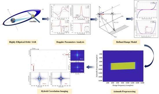
In this paper, we first establish the geometric model of the highly elliptical orbit SAR to derive the echo signal model expression and analyze the Doppler parameters characteristics in
Section 2. Secondly, considering the variation characteristics of Doppler parameters in the whole orbit period affected by the orbit curvature and its particularity, we derive and propose the R4-ESRM for HEO SAR in
Section 3, which breaks through the limitation of MESRM. It is verified by comparison simulation with other models. In
Section 4, the preprocessing method and hybrid correlation imaging algorithm are developed. Simulation results are provided to verify its feasibility. Finally, the conclusions are drawn in
Section 5.
3. Modified Range Model Based on HEO SAR
The traditional SAR range model is based on the geometric assumption of a straight flight trajectory. However, for HEO SAR, the relative motion relationship between the satellite and the ground target gets more complicated due to the influence of eccentricity and the introduced acceleration. In order to establish a more refined and applicable range model for SAR, we propose an improved MESRM to describe the range history of HEO SAR more accurately, which lays the foundation for following imaging algorithm research.
The MESRM proposed in [
27] shows the improved accuracy in ultrahigh-resolution case, as follows
the variables in (2) can be calculated as
where
is the azimuth time,
and
represent the equivalent velocity and the equivalent squint angle respectively and
is the slant distance at Doppler center time. It was proved that a higher azimuth resolution can be accommodated by MESRM.
However, it is worth noting that the solution of
in the above model is based on the assumption of (
)
2 +
while the case of (
)
2 +
may appear near the apogee of HEO, which means the
that needs to be fixed and rebuilt. Therefore, before introducing the new improved range model suitable for whole HEO period, the problem of infeasible area in HEO SAR imaging processing caused by
shown in
Figure 3b should firstly be discussed and analyzed. If one takes the HEO with eccentricity of 0.6 as an example, it can be seen from
Figure 5 that if the imaging algorithm based on MESRM is adopted, since
, the infeasible area range of HEO SAR accounts for 3/4 of the entire orbit, and the feasible areas for imaging only accounts for 1/4. In order to realize the imaging of the full orbital period of HEO, it is necessary to establish an entire orbit range model which can accurately describe both perigee, apogee and squint subduction section.
Concentrating on the formula below to elaborate the phenomenon of
and
:
where
;
denotes the signal wavelength;
denotes the distance between SAR and target. When
, the critical condition can be obtained by
where
,
and
represent the position, velocity, and acceleration vectors, respectively. The
denotes the angle between
and
. During the period of HEO SAR operating, if the motion vector meets the Equation (6) above, MESRM will not be able to represent the range model in HEO SAR so that the concept of
has lost its physical significance. Therefore, the MESRM is only suitable for the case of
, the equivalent squint angle
and
can no longer be used in MESRM which needs to be improved to have universal applicability.
The novel range model R4-ESRM is established to achieve overall applicability in HEO SAR:
The changing of
under R4-ESRM near the zero point
is shown in
Figure 6, which can intuitively see the influence of zero point on
under R4-ESRM. However, it does not affect the fitting effect of R4-ESRM on the whole period of HEO.
In the first place,
Figure 7 directly illustrates the inapplicability of the original MESRM to apogee and squint subduction section in HEO SAR.
Figure 7b,c show the phase error with MESRM at squint subduction and apogee brought by the
in HEO. It can be observed that the phase error caused by MESRM even reach
, which strongly proves that MESRM fails to describe the whole range history of HEO SAR.
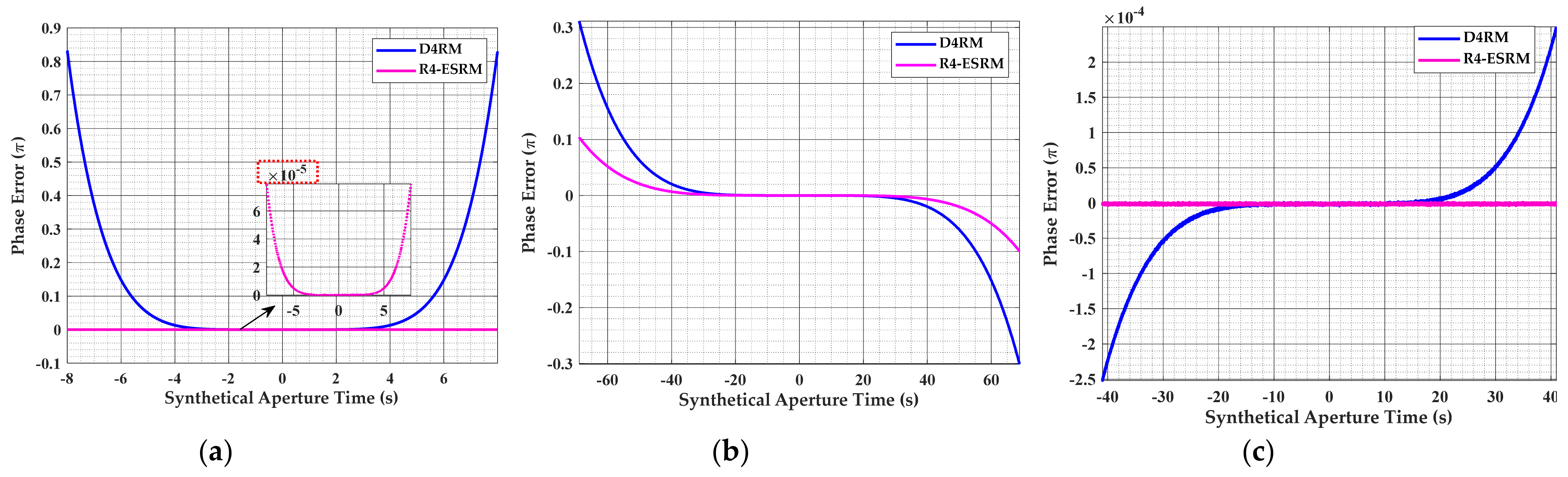
In order to verify the accuracy of the proposed model, with the eccentricity of 0.6 and other orbit and radar parameters listed in
Table 1, the phase errors caused by the range deviation of fourth-order Taylor expansion range model (D4RM) and R4-ESRM at different positions of HEO in the eccentricity of 0.6 are compared and shown in
Figure 8.
Figure 8a–c compares the phase error of D4RM and R4-ESRM at perigee, the squint subduction section and apogee, respectively. Under the azimuth phase error criterion of 0.25π, it can clearly be seen that R4-ESRM is more accurate than D4RM. As
Figure 8a shows, the maximal synthetic aperture time for D4RM is less than 14s at perigee. However, with the presented R4-ESRM, the phase error is less than
even if the synthetic aperture time is up to 16 s. The better performance of R4-ESRM can also be shown at other positions in
Figure 8b,c. As a result, R4-ESRM achieves the construction of a precise range model for entire period of HEO SAR, which can meet the requirements of HEO SAR imaging processing applications.
4. HEO SAR Imaging Algorithm
Based on the analysis of the geometry and Doppler characteristics of HEO sliding spotlight SAR in
Section 2, combined with the proposed R4-ESRM in
Section 3, the derivation of the imaging algorithm based on R4-ESRM is presented here, which combines the preprocessing with hybrid correlation. The process and framework of squint mode HEO SAR imaging algorithm is shown in
Figure 9, where FFT and IFFT denote the operation of fast fourier transformation and inverse fast fourier transformation, respectively.
The first part is preprocessing, which aims to remove 2-D spectrum aliasing phenomenon caused by the steering of antenna beam in sliding spotlight mode; the second part is coarse focusing based on R4-ESRM and the exact analytical expression of the echo signal in the two-dimensional spectrum is more complex to derive; the last part is to compensate the residual phase error by using hybrid correlation with kernel gate function to achieve accurate data focusing.
4.1. Azimuth Deramp Preprocessing
Based on the imaging geometry of the large elliptical orbit, the demodulated signal of the SAR echo signal model is given by
where
and
denote the antenna pattern functions in the range and azimuth directions respectively;
represents the scattering coefficient;
is the speed of light,
is the range chirp rate,
and
are the fast time and azimuth slow time respectively. The expression of the echo signal in the range frequency and azimuth time domain is given by
where
is the carried frequency, and
denotes the Doppler frequency modulation rate of reference target. For inducing Azimuth preprocessing, the azimuth spectrum aliasing is further analyzed below. The 2-D spectrum diagram is elaborated in
Figure 10.
Where
denotes the additional bandwidth coupling with the range frequency domain and azimuth frequency domain. As shown in
Figure 10, the spectrum skews significantly as squint angle increases, which leads to the aliasing and the increase in
. And
is the signal bandwidth,
The influence of the Doppler center frequency in the range frequency domain by the coupling term by [
30]
where the two terms in the formula all include the azimuth shift caused by squint angle
. We can observe that the second term is the function with respect to
, resulting in the phenomenon of 2D-spectrum skew.
The following is concentrated on the preprocessing by the Deramp method and nonlinear phase correction to eliminate the azimuth aliasing and spectrum skews. The preprocessing function is given by
where
is the azimuth sampling number. The first term of (11) is the Deramp operation which denotes that the received signal is convolved with the reference linear frequency modulation signal with the opposite Doppler frequency in the azimuth time domain so that it can effectively reduce the instantaneous azimuth signal bandwidth and alleviate the contradiction between the PRF and the Doppler bandwidth. The second term is the operation of the Doppler center frequency shift. After the above step, since PRF is still less than the total bandwidth caused by squint mode as discussed in
Figure 10 above, the aliasing of azimuth spectrum still exists. Therefore, the third term is presented to carry out the nonlinear phase correction which can effectively remove the coupling effect between range and azimuth in frequency domain and pave the way for further spectrum expansion.
After the first multiplication process is completed, the signal takes the azimuth FFT and the second multiplication can be completed by
where
means to round down,
is the new azimuth sampling time decided by the new PRF calculated as
.
In order to better illustrate the effect of the above preprocessing, as shown in the
Figure 11a, it is evident that the original 2-D spectrum is seriously aliased and the boundary of the azimuth bandwidth cannot be distinguished at all. By taking the Deramp step,
Figure 11b shows that even though frequency-domain aliasing has been removed, the phenomenon of spectrum folding still exists. Thus, nonlinear correction is necessary to be adopted to make the spectrum equivalent to that in the side-looking.
Figure 11c shows that the phenomenon of the 2-D skew spectrum disappears after compensating the third term used for nonlinear phase correction. So far, the above results fully prove the effectiveness and correctness of the proposed preprocessing.
Although the above operation removed the spectrum distortion, a new problem is introduced whereby the image scene has geometric distortion and azimuth translation invariance is no longer applicable. As shown in
Figure 11d, spectrum expansion is generally adopted to restore the original tilted shape of the spectrum in the frequency domain. Finally, spectrum aliasing is removed by preprocessing combing Deramp operation with nonlinear phase correction.
Then, the expression of the echo signal in the 2-D frequency domain can be obtained based on proposed range model R4-ESRM by using the principle of stationary phase (POSP) [
31] and Fourier transformation as bellow:
where
is the azimuth frequency and the stationary point
is generally solved by reversion of the series (ROS) [
32] method and PSOP. However, ROS is based on the transformation between polynomial series and its inverse function, which is not suitable for the proposed model in this paper, so the POSP is adopted in this paper.
can be obtained by solving the equation:
Since the square root of R4-ESRM contains cubic terms and quartic terms which are much smaller than the first term, the effect of ignoring high order terms can be taken no consideration into the solution to the stationary phase points by using the POSP. By derivation, the 2-D spectrum of the preprocessed signal is given by
where
4.2. Coarse Focusing and Hybrid Correlation Processing
As previously discussed, the phenomenon of azimuth aliasing is eliminated after preprocessing, then the coarse focusing is proposed in this section. Considering that the range cell migration (RCM) increases with the shift of the range gate from the center of the scene, a huge amount of computation will be introduced in if the kernel function in hybrid correlation [
33] is used for imaging. Therefore, we first use the phase compensation of the center of the scene as the unified reference coarse focusing function of the entire scene, and perform it on the preprocessed echo in the 2-D frequency domain consistently, which will compensate most of the phases corresponding to different range gates and effectively reduce the RCM. The reference function is given by
where
,
,
,
,
is the parameters of the reference point target in the scene, as well as the
and
. In the formula of (17), the first term is used for range compression, the second term is used to compensate for the extra factor introduced by Deramp operation, the other terms are used for phase compensation corresponding to by the range history.
After the coarse focusing by multiplying and , the referenced point target in the center of scene has been precisely focused, that is, the corresponding range cell migration (RCM) is completely corrected, and most of the RCM of other range cells are corrected, but there still exists residual migration. Therefore, it is necessary to construct the kernel function according to each range gate as a reference and adopt hybrid correlation imaging. Since the coarse focusing has been conducted before the imaging processing, the window length of the subsequent kernel function and the amount of calculation are both greatly reduced, which improves the efficiency.
The kernel functions corresponding to different range gate is given by
Considering that different position of the targets occupies the same Doppler azimuth terms in the Doppler domain, it can be completed through correlation. After the locally extracted data is conjugate multiplied with the corresponding kernel function, the azimuth IFFT is performed, and the RCM correction and the azimuth phase compensation are completed at the same time. Finally, the residual phase errors are well compensated in order to obtain high precision focused result. At this stage, the correction of residual RCM by hybrid correlation algorithm (HBA) for each range bin can be expressed as
where
is the number of range bin,
is the length of the selected window,
denotes the echo data of the
th range gate,
is the number of RCM and
aims to get the conjugate value.
4.3. Azimuth Resampling
To avoid the azimuth time domain aliasing caused by the Deramp operation in the preprocessing, the azimuth resampling is adopted to achieve the de-rotation processing, with the function given by
where
is the hybrid factor. After performing the azimuth IFFT, the function of residual phase compensation can be expressed as
5. Results
In order to verify the correctness of the theoretical analysis and the effectiveness of the proposed imaging method, two simulation experiments are carried out in this section. The first experiment is to use the hybrid correlation imaging algorithm based on the R4-ESRM to perform imaging at different positions throughout the entire period of the highly elliptical orbit to verify the range model as well as the accuracy and feasibility of imaging methods. The simulation parameters are shown in
Table 2. For perigee, the focused result of proposed imaging algorithm at perigee in HEO for high resolution are shown in
Figure 12. Then, the imaging simulation experiments are performed at apogee and the squint subduction section of HEO to compare the focusing results based on R4-ESRM and other range model for different case by using the proposed imaging algorithm, respectively.
By performing HBA based on R4-ESRM, the targets are well focused as shown in
Figure 12, which shows the contour plots of the imaging results at different orbital moments in the highly elliptical orbit based on R4-ESRM. It can be derived from the above simulation results that the preprocessing and the hybrid correlation imaging algorithm based on R4-ESRM can achieve focused imaging regardless of the perigee, apogee, or other orbital positions. After the azimuth preprocessing with Deramp operation, the azimuth aliasing is well eliminated. To further study and quantify the performance of the imaging results using the proposed approach and method, the point target analysis results are listed in
Table 3.
According to the
Table 3, the ρ
r_s and ρ
a_s denote the theoretical range resolution and azimuth resolution respectively, where the peak sidelobe ration (PSLR) is −13.26 dB and the integrated sidelobe ratio (ISLR) is −10.15 dB by using the rectangular window. From the presented data results, it well indicated that the point target in HEO SAR can be accurately focused regardless of the perigee, apogee or other orbital positions based on R4-ESRM and proposed algorithm.
The second experiment is to perform hybrid correlation imaging on 4 × 4 dot-matrix targets in the scene of the highly elliptical orbit SAR at the apogee moment with the parameters in
Table 4. The simulated scene is shown in
Figure 13, where the distance of different targets along the range and azimuth are both 18 km. The distance between each target is 6 km and the theoretical azimuth resolution and range resolution are 1.2 m.
In this part, the simulated HEO SAR data are used to analyze the characteristics of the signal before and after the proposed method is applied.
Figure 13a shows the amplitude of the distributed targets’ raw data of spaceborne HEO SAR and
Figure 13b gives the 2D-spectrum of focused SAR data without aliasing in azimuth aliasing.
To further prove the precise focusing by hybrid correlation based on R4-ESRM with the kernel gate function,
Figure 14 shows the final result of focused data and compares the results before and after the precise focusing, especially, as the edge target A and B are marked in
Figure 14. It can clearly be seen that the algorithm of constructing the kernel function with the precise Doppler parameters and imaging parameters corresponding to the range gate can achieve the target of each range gate be accurately focused, and the side lobes on both sides of the point target are obviously suppressed, which verifies the effectiveness and accuracy of the hybrid correlation algorithm, and all of the targets in the scene are well phase compensated and focused.
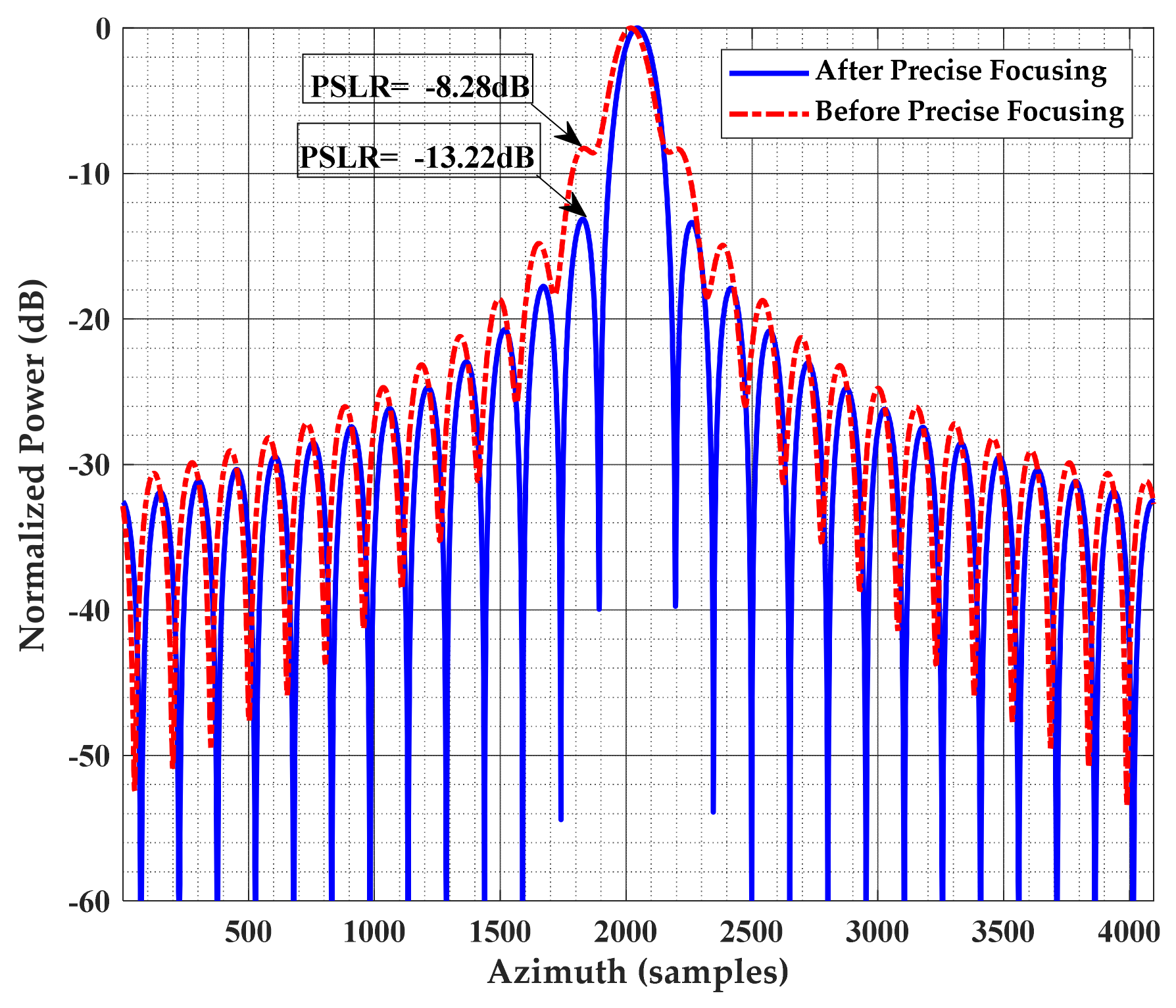
Figure 15 compares the azimuth profile comparison of the edge point target A before and after the precision focusing. The PSLR has decreased from −8.28 dB to −13.22 dB, resulting in better sidelobe suppression and focusing. It can clearly be seen from the above that the algorithm of constructing the kernel function with the precise Doppler parameters and imaging parameters corresponding to the range gate can achieve the target of each range gate to be accurately focused, and the side lobes on both sides of the point target are obviously suppressed, which verifies the effectiveness and accuracy of the hybrid correlation algorithm, and all of the targets in the scene are well phase compensated and focused.
6. Discussion
In this subsection, we compared the imaging results based on R4-ESRM and MESRM at perigee, apogee, and squint subduction sections, respectively, in order to better highlight the advantage of R4-ESRM, which can describe the range history of SAR in the full period of highly elliptical orbit, while other models can only be applied in the certain segment of HEO. The 5 × 5 dot-matrix is used for the simulation experiment, and the performance of the imaging results is verified by evaluating the edge target C as shown in
Figure 16. Here, the scene setting sizes of perigee, apogee and squint subduction sections are 1 × 1 km, 6 × 6 km and 18 × 18 km, respectively.
Figure 17 show the imaging results obtained by MESRM and R4-ESRM combined with the proposed imaging algorithm at different position in HEO. The SAR echo data of several representative positions in highly elliptical orbit: perigee, squint subduction section and apogee were used for imaging based on MESRM and R4-ESRM, respectively.
Figure 17 fully proves the applicability of R4-ESRM to the whole orbit of HEO, and the agood, focused result can be obtained by using the hybrid correlation imaging algorithm based on R4-ESRM. As shown in
Figure 17d,e, when the Doppler frequency of apogee changes to negative as −11.24 Hz/s and −17.94 Hz/s, the imaging result has been completely defocused. This shows that MESRM fails to describe special range history variations in highly elliptical orbits, whereas R4-ESRM does.
7. Conclusions
In this paper, a refined fourth-order equivalent squint range model and imaging method for slide spotlight SAR are proposed for highly elliptical orbit. For the proposed method, we first establish the geometric configuration of HEO SAR and derive the relationship between eccentricity and perigee and apogee based on Kepler equation, so that the shape of HEO and the motion trajectory of satellite can de designed. On this basis, we carry out the study of range model for HEO SAR. The Doppler parameters characteristics are first analyzed in this part to observe the influence of highly elliptical orbit on Doppler parameters more obviously, and to pave the way for the establishment of the refined range model. Experiments verify that the azimuth FM rate will change from positive to negative in highly elliptical orbit, which will lead to the inability to solve the equivalent velocity in traditional ESRM and MESRM. To solve this problem, the R4-ESRM is proposed to achieve overall applicability in the whole orbit period of HEO SAR without using the equivalent squint angle and equivalent velocity. The comparative experiment of phase errors caused by MESRM and R4-ESRM strongly shows that the proposed R4-ESRM could accurately describe the whole range history of HEO SAR, which verifies the effectiveness of R4-ESRM for HEO SAR.
Combined with the R4-ESRM, the imaging algorithm based on hybrid correlation is presented. It is divided into four stages, azimuth preprocessing, coarse focusing, precise focusing and resampling respectively. The azimuth preprocessing adopts the Deramp operation to remove the aliasing in azimuth frequency domain caused by the sliding spotlight mode and introduces the nonlinear phase correction to remove the spectrum tilt caused by squint angle that aims to avoid the mutual folding of the spectrum. After the preprocessing, the reference function for coarse focusing based on the exact analytical expression of signal in the 2D-frequency domain based on R4-ESRM is constructed, which corrects most of the RCM for all range cells. Then, by constructing kernel function for each range cell and imaging with hybrid correlation, the residual phase compensation is realized, and the targets are well-focused. Finally, the azimuth resampling is adopted to avoid the influence of Deramp operation. As demonstrated by point target simulation results, it achieves the precise phase compensation and well focusing so that the accuracy and effectiveness of the imaging algorithm and range model are well verified by the simulation experiment results.
Since the proposed algorithm focuses on each range cell, further acceleration of the algorithm is considered in the future. In addition, we would like to envision the future applications of highly elliptical orbit SAR, since there are no SAR satellites currently operating in HEO at present. By setting perigee and apogee positions, HEO SAR can conduct large-scale observation and imaging of areas of interest at high latitudes, such as sea routes and ecological surveys in the Arctic, which can also achieve high-resolution imaging of areas near the equator. Therefore, HEO SAR has broad application prospects in the future, and it deserves further exploration.


