Article

RMCSat: An F10.7 Solar Flux Index CubeSat Mission

1
Royal Military College of Canada, Kingston, ON K7K 7B4, Canada
2
Royal Australian Air Force Headquarters, Canberra 2600, Australia
*
Author to whom correspondence should be addressed.
Remote Sens. 2021, 13(23), 4754; https://doi.org/10.3390/rs13234754
Submission received: 16 October 2021 / Revised: 14 November 2021 / Accepted: 20 November 2021 / Published: 24 November 2021

Abstract

:
The F10.7 solar flux index is a measure of microwave solar emissions at a wavelength of 10.7 cm or 2800 MHz. It is widely used in thermosphere and ionosphere models as an indicator of solar activity and is recorded at only one terrestrial observatory in Penticton, Canada during daylight hours. The lack of geographical and temporal coverage of F10.7 measurements and no external redundancy to the existing system has led to the development of the RMCSat mission, which seeks to demonstrate the feasibility of collecting microwave solar flux emissions from a space-based platform. RMCSat is the first CubeSat mission by the Royal Military College of Canada. It offers a training environment for personnel in space mission analysis and design, satellite assembly, integration and testing, and satellite operations. This paper introduces the mission concept and preliminary design of a space-based solution that captures solar density flux measurements during each orbit as the Sun passes through the boresight of the primary payload antenna. In addition to two channels recording the 2800 MHz frequency (2785 MHz and 2815 MHz), a third channel records 2695 MHz using the same calibration standard to determine if the United States Radio Solar Telescope Network (RSTN) could be leveraged to supplement the existing F10.7 solar flux measurements and improve solar flux approximations. The RMCSat mission, satellite design, and system budgets are demonstrated here as being viable. Future design considerations pertain to the payload antennas and achievable launch orbits.

Graphical Abstract

1. Introduction

Microwave solar emissions at a wavelength of 10.7 cm, or 2800 MHz, are an excellent indicator of solar activity. Measurements of the solar flux density at this wavelength are known as the 10.7 cm solar radio flux, or the F10.7 index. This index is widely used in thermosphere and ionosphere models because these microwave emissions correlate well with other solar emissions such as extreme ultraviolet (EUV), ultraviolet (UV), and X-rays, which originate from similar regions of the solar atmosphere, namely the upper chromosphere and base of the corona. The correlation with EUV is of particular interest as solar EUV flux is the main energy source in the terrestrial atmosphere producing ionization, disassociation, excitation, and heating [1,2,3]. Variability in the ionization levels in the ionosphere affects the propagation of radio waves, which in turn can cause errors in terrestrial and satellite communication and navigation signals [4]. The heating of the neutral atmosphere in the thermosphere causes drag forces to increase on Low Earth Orbit (LEO) objects, disrupting the orbital paths of satellites [5,6,7]. Consequently, the monitoring of the EUV flux is important for thermosphere and ionosphere studies and space weather predictions.
The most notable benefit of microwave solar emissions is that they can reach the surface of the Earth, while EUV wavelengths are absorbed by the atmosphere, as shown in Figure 1. The atmospheric window for 10 cm microwaves has been critical for F10.7 observations historically. It has also made the measurement of F10.7 solar flux exceptionally robust because it can be reliably and accurately recorded from the ground in all weather conditions with few gaps or calibration issues [8]. F10.7 measurements were therefore used as a proxy for EUV measurements, which were unable to be directly measured until the dawn of space-based platforms in the late 20th century.
While EUV flux can now be monitored from space platforms, the highly reliable and repeatable calibration of the F10.7 solar radio flux measurement, along with its continuous historical record, has maintained its standing as one of the most widely used space weather indices [1,10,11]. It is a key input parameter to atmospheric models and provides climatology of solar activity over six solar cycles [6,8,12]. This duration is only surpassed by sunspot records [13].
Observations of F10.7 solar flux were initially recorded by radio telescopes based near Ottawa, Canada from 14 February 1947 to 31 May 1991 [1]. As of 1 June 1991, the Dominion Radio Astrophysical Observatory (DRAO) in Penticton, Canada is the only ground-based observatory to collect daily measurements. Two radio telescopes onsite collect three one-hour-long solar measurements per day during daylight hours [1].
While measurements have been historically reliable, the inherent vulnerability of a single-station measurement represents a potential point of failure in global ionospheric and thermospheric modeling [14]. Furthermore, F10.7 is currently under-sampled, with the three daylight measurements from a single site constrained further by the effects of local terrain on usable solar elevation angles. The solar flux output is known to vary over a range of timescales, from intense bursts at millisecond to minute scales, to smaller variations over hours to days, following an overarching 11-year solar cycle [1]. The received 10.7 cm flux of interest will vary over the course of a day as active regions rotate across the surface of the Sun. The magnitude of these variations is often more than a solar flux unit and increases with the level of solar activity. Discrete measurements obtained from a single geographic location over a three-hour total observation period would not necessarily capture these variations and therefore not provide certainty of the average solar flux value.
The problem of under-sampling has been identified by the current observation program and a mitigation strategy of multiple ground-based stations in different longitudes has been suggested [1]. The investment required to implement this strategy could be substantial; however, if a strong correlation between 2800 MHz and another solar density flux frequency, 2695 MHz, can be established, the existing monitoring system of the latter frequency could be leveraged, with observations scaled to provide improved temporal coverage and thus more accurate F10.7 solar flux approximations. The United States Radio Solar Telescope Network (RSTN) is a distributed network of ground-based radio telescopes dedicated to measuring solar flux densities across a range of microwave frequencies from 245 to 15,400 MHz, including 2695 MHz. Four stations constitute the network, located in Massachusetts, Hawaii, Southern Italy, and Western Australia. Meaningful comparisons between RSTN and DRAO measurements are not currently possible, due to differing instrument calibration standards and operational regimes between the two programs [15,
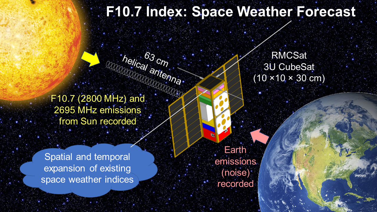
16]. As such, 2695 MHz data are currently unable to be scaled and directly substituted for F10.7 index applications. This paper introduces the mission concept and design of a space-based solution that would increase the geographical and temporal coverage of F10.7 measurements and provide redundancy to the existing solar monitoring system. A CubeSat platform is proposed by the Royal Military College of Canada (RMC) for extra-terrestrial solar flux observations of 2800 MHz and 2695 MHz frequencies. Satellite observations of 2800 MHz will increase the number and temporal coverage of daily F10.7 measurements available. The inclusion of solar flux emission observations at 2695 MHz into the mission of RMCSat allows for accurate comparisons between 2800 MHz and 2695 MHz without calibration issues, as the same instrument is collecting both frequencies at the same time. This will enable the accurate determination of the relationship between 2695 MHz and 2800 MHz flux values, act as an independent calibration source for RSTN terrestrial measurements during overlapping operations windows, and facilitate the use of RSTN flux values to critically supplement the existing F10.7 observation dataset. RMCSat is a technology demonstrator intended to validate the measurement of F10.7 from space that will allow the use of existing RSTN stations as new nodes in a continuous-observation global ground network. The use of satellite technology for this endeavor is a cost-effective approach compared to a worldwide network of perfectly calibrated solar observation stations.
RMCSat is the first CubeSat mission undertaken by RMC and provides the additional benefit of being a training environment for personnel in space mission analysis and design, satellite assembly, integration and testing, and satellite operations.
An overview of the RMCSat mission is presented here, describing the physics of F10.7 solar radio flux in Section 2, and the mission objective, the performance requirements, and the baseline mission concepts in Section 3. The 3U CubeSat satellite architecture is then outlined in Section 4 along with system budgets. A discussion of the future design considerations in Section 5 precedes the conclusion of the paper.

2. F10.7 Index

The measurement of solar flux is based on the fundamentals of blackbody radiation. According to the Stefan-Boltzmann law, a perfect blackbody will emit energy based on its surface area A and its absolute temperature T in Kelvin. The total isotropic power P emitted across all frequencies is given by,
P A = σ T 4 ,
where σ = 5.67 × 10 8 W m 2 K 4 is the Stefan-Boltzmann constant. The spectral radiance of an object of a given temperature does vary with frequency. When observed at a particular frequency, the spectral radiance B v of emissions from an object follows Planck’s Law,
B v = 2 h v 3 c 2 1 e h v k B T 1 ,
where v is the wavelength of emission, h = 6.63 × 10 34 Js, is the Planck constant and k B = 1.38 × 10 23   m 2 k g s 2 K is Boltzmann constant. In the case of microwave frequencies at solar temperatures, where h v     k B T , the Rayleigh-Jeans approximation can be used to simplify Equation (1) for solar radiation analysis where,
B v = 2 k B T v 2 c 2 = 2 k B T λ 2 .
Spectral radiance is a characteristic of the emitting source, the Sun in this instance, while intensity is what is observed by a receiver, the antenna. The specific intensity I v is given as
I v = 2 k B T b v 2 c 2 = 2 k B T b λ 2 .
If the specific intensity of the radiation source is integrated over the total solid angle subtended by the emitting source Ω s , as measured at the detector, the result is the spectral flux density S v ,
S v = I v c o s θ d Ω .
By using the small-angle approximation for the cosmic radio sources,
S v = I v d Ω = I v   Ω s .
Given Equation (4), the spectral flux density becomes,
S v = 2 k B T b   Ω s λ 2 ,
where S v is the power per unit area per unit bandwidth due to the source measured at wavelength λ . This is the measurement of solar flux density commonly used for solar activity analysis and is the basis for F10.7 measurements which focus on an average wavelength of 10.7 cm.
The F10.7 index is the total power flux density, S v , from all sources on the solar disk at 10.7 cm within a bandwidth of 100 MHz centered on 2800 MHz, averaged over an hour [1]. It is comprised of three components: a constant one from quiet Sun background emissions; a slowly varying component (S-component) that originates in active regions and; and a highly variable one resulting from radio burst emissions [1,10]. The recorded flux density at this wavelength varies daily. It is expressed in solar flux units (sfu) or 10−22 W/mHz and can vary from approximately 64 sfu to greater than 300 sfu over the solar cycle [1].
Flux measurements taken from the ground-based DRAO are obtained using two 1.8 m diameter paraboloid radio telescopes that run in parallel. They are referred to as Flux Monitor 1 and Flux Monitor 2; the latter acts as the primary instrument while the former is a backup [1]. During the northern hemisphere summer months, measurements are taken each day at 1700, 2000, and 2300 UTC, and in winter at 1800, 2000, 2200 UTC due to the reduced daylight duration. Readings are taken both on-Sun and off-Sun, to obtain accurate background cold-sky values. The solar data are then corrected for atmospheric absorption, background sky temperature, and antenna gain [17]. Precise calibration standards are maintained through annual calibration and validation of both flux monitors against an external reference source, a large pyramidal horn antenna maintained onsite at the DRAO.
When detecting solar flux density from a space-based platform in LEO, the sensor antenna receives signals from multiple external sources: the desired solar radio flux, microwave thermal emission from the Earth, electronic radio-frequency interference (RFI) from Earth-based and airborne radars and transmitters, and background emissions from Cosmic Microwave Background radiation and other galactic sources [18]. The strength of these different signals will vary constantly, dependent on the position and pointing direction of the satellite, complicating solar flux measurement. The signal detected by the antenna also includes noise generated from the receiver system itself. The solar signal, and small variations in this signal, must be distinguishable among all of the noise.
Knowledge of an antenna gain pattern is useful to understand the issue of background noise detection. In Figure 2, an antenna directive gain elevation pattern is shown for a simple helical antenna, like that used by RMCSat. The solar signal is detected by the main beam while attempts are made to minimize the background signals detected by main, minor, and background lobes.
For changes in the solar flux density to be detected, the antenna must have sufficient sensitivity and minimal noise from other sources. Each source contribution to the antenna temperature T A s can be determined by,
T A s = Ω s 4 π T B s G ,
where T B s is the brightness temperature of the source, Ω s is source solid angle and the gain G is applicable to the region of the antenna pattern that the signal is localized within.
In the first instance, a certain detection threshold must be achieved for the solar emissions at 10.7 cm. Based on existing F10.7 data, a minimum value of 70 sfu for F10.7 emissions over the solar cycle results in an isotropic antenna temperature of 0.23 K at 10.7 cm. If a flux measurement is to have an accuracy of 1%, as is required for ground-based DRAO F10.7 determinations, then the required antenna sensitivity is 2.3 × 10⁻³ K. This value can be increased if a more directional antenna beam is used, since a higher main beam gain ( G M B ) increases the tolerance of the system to noise signal fluctuations [1]. The antenna sensitivity for F10.7 = 70 sfu becomes,
Δ T A r e q = 2.3 × 10 3 G M B .
The effect of terrestrial thermal emissions is more complicated as the brightness temperature of Earth changes as a satellite passes over different landscapes. A maximum average brightness temperature of 300 K (land) and a minimum value of 100 K (ocean) have been estimated [18]. The 200 K fluctuation between the minimum and maximum terrestrial brightness temperatures results in an antenna temperature difference of 0.61 K. This is two orders of magnitude greater than the required antenna sensitivity and nearly three times the value for 70 sfu. Even if a higher gain of 20 dBi is achieved by RMCSat, the detection threshold only reaches 0.33 K. Thus, fluctuations in thermal emissions from Earth are sufficient to obscure the primary solar signal detected by the payload and must be accounted for in some manner.
Similarly, electronic radio-frequency interference (RFI) from Earth and airborne communication systems presents a significant issue. Microwave signals of sufficient power are detected by an orbiting radiometer due to atmospheric transparency [18]. The frequency band of 2700 to 2900 MHz hosts global aeronautical navigation systems, radar weather monitoring, and maritime and land-based radiolocation services [19,20,21,22]. Transmitter peak output powers range from 22 kW up to 1.4 MW [19]. Using a bandwidth of 100 MHz, equivalent to the DRAO F10.7 measurements, the equivalent antenna temperature contribution from a radar system such as the Next Generation Weather Radar (NEXRAD) is 6.1 × 10¹⁴ K [18]. Such a signal would saturate the receiver. Fortunately, the low duty cycle and short duration of signal pulses mean that it is not expected to cause significant issues for the overall utility of measurements. The 2695 MHz band is a protected frequency and is not expected to have radar inference. Consequently, it can be used for comparison to identify RFI within the F10.7 data.
Cosmic microwave background radiation is a homogeneous field that has near-perfect blackbody radiation at a temperature of 2.748 ± 0.016 K. The antenna temperature contribution is 2.09 K, but being constant, it is easily taken into account. The galactic center also produces radiation and an antenna temperature contribution of 2.86 × 10⁻³ K. For a directional antenna like that of RMCSat, issues in solar flux measurement accuracy will occur where the galactic center is within the main beam and solar activity levels are low. Given the fixed position of the galactic center, this contribution can be anticipated and accounted for.
System contributions are generated from thermal noise resulting from resistance in radiometer components and transmission line losses between the antenna and receiver [23,24]. The magnitude of fluctuations in system noise limits the minimum detectable antenna temperature change. Since fluctuations are random and have shorter timescales than the primary signal, they can be reduced towards a zero mean by averaging the total signal over a selected integration time [23,24].
The analysis of the radio environment of RMCSat indicates that the thermal radiation from Earth is the greatest concern, followed by RFI. Proposed mitigation options include a fixed orientation of the satellite towards Earth, a secondary antenna, and measurements are taken across two close but separated channels. The fixed orientation places the Earth in the lowest gain region (sidelobe and backlobe) of the primary antenna. Fluctuations that are detected can then be attributed to changes in the brightness temperature of the surface below. A secondary antenna directed at the Earth offers a means to capture the surface signal and use it for comparison with the primary antenna signal. Changes in Earth emissions will be apparent in the secondary antenna signal. Post-processing can be used to remove the Earth component from the primary signal. A wide beam secondary antenna is necessary to replicate the area visible to the main payload antenna and allow for an accurate comparative signal. Preliminary modeling indicates that sufficient accuracy can be achieved using this method [18].
In place of a single 2800 MHz channel, the use of two close but separate channels is selected to account for electronic RFI signals and the saturation of the receiver when these are present. Measurements are taken at 2785 MHz and 2815 MHz (designated F10.7- and F10.7+ respectively) with a narrower bandwidth of 20 MHz for each to minimize the chance of an RFI signal present in both channels. The dual channels provide data continuity if one channel is affected, and provide a method to distinguish between RFI signals and solar burst emissions. The inclusion of 2695 MHz monitoring in the mission provides additional control, as interference found in all three channels indicates a solar burst as the most likely cause. For a meaningful F10.7 solar flux record, the measurements obtained by the F10.7− and F10.7+ channels can be combined in post-processing to obtain the equivalent average 2800 MHz value.
Finally, the calibration of a radiometric sensor is critical to system accuracy. Importantly, the space-based solar monitoring regime will allow up to three RMCSat observations per day that are concurrent with the DRAO solar observations. This will allow a highly accurate reference for calibration and validation of RMCSat values.

3. RMCSat Mission

The mission of the RMCSat is to demonstrate the feasibility of measuring solar flux density from a nanosatellite platform in LEO. The mission seeks to develop, design, and build the first CubeSat mission of RMC, with an overall purpose of training highly qualified personnel in the general areas of space mission analysis and design, integration and assembly, satellite operations, space weather, and solar activity. The primary objectives of the mission in Table 1 must be achieved while the secondary objectives in Table 2 are desirable outcomes.

3.1. Performance Requirements and Constraints

RMCSat performance requirements are driven by the frequency detection and accuracy required, and by the radio noise environment of the satellite. The primary payload must be able to receive and record three solar frequencies simultaneously (2695 MHz, 2785 MHz, 2815 MHz). It must also be able to detect variations in these flux density signals to a satisfactory threshold. For the observations to be scientifically relevant, the same accuracy assigned to DRAO F10.7 readings is used. DRAO gives its published observations an accuracy of 1 sfu or 1%, whichever is greater [1]. Such measurements are heavily influenced by the gain pattern of the main antenna beam and the boresight angle of the antenna which, in turn, define the pointing requirements for the attitude determination and control system (ADCS).

3.1.1. Pointing Requirements

An analysis of the main beam of the chosen helical antenna was performed using the ANSYS Electronics Desktop High-Frequency Structure Simulator (HFSS) [18]. An F10.7 signal of 100 sfu was simulated at 2800 MHz. This frequency generates a narrower beam pattern for the payload antenna compared to 2695 MHz. Figure 3a shows the primary lobe of the antenna gain response pattern and the influence of the boresight angle. The maximum detected value of the gain pattern occurs when the boresight angle is at zero degrees; lower values result from off-boresight angles. Figure 3b shows a close-up of the same gain pattern. Here, the red dotted line indicates the desired 1% signal measurement accuracy. While the curve is asymmetrical, a boresight angle tolerance of 1.3° is required to achieve accuracy. Based on this analysis, an overall pointing accuracy ≤1° is proposed for RMCSat, with a pointing knowledge of 0.5° and pointing accuracy of 0.5°.
It should be noted that these pointing requirements are based on the chosen helical antenna and will require further verification once the final antenna is selected. A narrower final beam pattern would require stricter pointing requirements. However, the proposed ADCS for the satellite, the MAI-400 [25], is a space-proven system that provides 0.1° accuracy, so it is unlikely that subsystem design changes would be necessary.

3.1.2. Radio Noise Interference Measures

For solar flux fluctuations to be distinguishable, radio noise interference must be sufficiently minimized. A fixed satellite orientation with respect to Earth is necessary to remove an additional degree of variation, and to keep terrestrial thermal emissions in the lowest gain region of the primary antenna beam. A suitable secondary antenna with a wider beam pointing earthward is required to capture Earth emissions for comparison and subtraction of the thermal emission from primary antenna measurements. The monitoring of two channels, at 2785 MHz and 2815 MHz, allows for the identification of RFI signals. A software-defined radio (SDR) architecture is used to allow flexibility in signal collection bands. If persistent mission-disabling interference is experienced by RMCSat within the sampled bandwidths, the use of an SDR payload, reconfigurable from the ground, allows satellite operational channels to be adjusted in response, separating sampling frequencies from the sources of disruptive RFI.

3.1.3. Deorbiting Requirements

The mission design life of RMCSat is one year, all components must continue to operate throughout this timeframe. While it is likely the mission will extend beyond this design life, international guidelines require satellites to deorbit from LEO within 25 years [26]. The results of an analysis conducted for three common CubeSat launch altitudes and various drag coefficients ( c D ) shown in Table 3 indicate an altitude of 550 km or lower is necessary for atmospheric drag forces alone to deorbit the satellite.
Consequently, a design altitude of 550 km is chosen to allow for drag forces to deorbit the satellite and to minimize thermal emission signals from Earth. A lower altitude is feasible if a launch altitude of 550 km is not possible, however, the impact of thermal noise environment and radio noise interference on the antenna would require re-calculation.

3.1.4. Orbit Parameters and Requirements

The type of LEO orbit required for the mission is heavily influenced by the required line of sight to the Sun, access to solar energy, and the expected radio interference from Earth. The chosen design orbit has implications for sub-systems, primarily the power system.
Maximum solar access is obtained by the sun-synchronous orbit (SSO), a precise inclination for a specific altitude that results in the satellite maintaining a fixed orbital plane orientation with respect to the Sun. Each SSO causes a satellite to cross the equator at the same local mean solar time. A dawn-dusk SSO offers near-continuous access to the Sun for solar observation and power generation throughout most of the year. In contrast, a noon-midnight SSO provides the least solar exposure. A diagram of the two orbits is shown in Figure 4.
The implication of these two orbits on payload operations makes the choice of orbit more complex. In a dawn-dusk SSO, the primary payload antenna is at a near-constant 90° angle to nadir (side-laying). A side-laying geometry increases the risk of strong interference from the large Earth solid angle affecting the main higher gain lobe regions. It also reduces the ability to use passive physical shielding techniques. Another concern is the increase in atmospheric signal attenuation resulting from the greater atmospheric transmission distance, at a near-maximum when 90° angle to nadir. Although attenuation is generally low, it may be difficult to quantify as the solar signal passes through multiple atmospheric layers of varying temperatures.
Two options exist for antenna pointing in a noon-midnight SSO: a fixed zenith pointing antenna and a sun-tracking antenna. Figure 5a illustrates that maximum solar observation time is achievable using a sun-tracking antenna, however, the atmospheric attenuation issues and lack of fixed pointing angle with respect to Earth-based noise sources makes this a non-viable option.
The zenith-pointing antenna option shown in Figure 5b results in greatly reduced observation times. However, it has the advantage of replicating the highly effective DRAO calibration observation pattern of taking cold sky views before and after solar flux measurements [1]. In the case of RMCSat, these cold sky views are achieved as the Sun passes through the known first nulls of the antenna pattern, with the peak solar flux measurements generated as the Sun passes through the antenna boresight. Figure 6 illustrates an operation cycle for solar observations from this configuration. An orbital period of 95.6 min allows for approximately 15 solar observation windows per day, achieving the first mission objective of the increased temporal and spatial coverage of F10.7 data.
A different SSO with a mean local time (MLT) other than noon-midnight is possible but requires an adjustment to the pointing regime of RMCSat to ensure that the Sun passes through the antenna boresight. A latitude shift of 15° per hour means that for each hour of MLT earlier or later than local noon, the satellite must be rotated about its velocity axis by 15° to align the peak gain of the payload antenna with the Sun. This tilt also affects any secondary antenna, changing the footprint of the Earth’s brightness temperature sensed and its ability to replicate the terrestrial thermal emission seen by the primary antenna. Figure 7 shows the offset of both the primary and secondary antenna beams. The amount of tilt required for an offset SSO remains fixed; so, if known in advance, the secondary antenna could be mounted at an angle to maintain nadir and compensate for the tilt.
A non-SSO results in a different MLT for each orbit and the payload antenna requires a different tilt offset applied on each successive pass. If effective shielding against radio interference is possible, such an orbit may result in usable observations, particularly if the orbital inclination is low. As orbital inclination increases, however, greater tilt offsets are required to align with solar declination, meaning some passes do not generate useful data due to Earth interference.
Ideally, a repeating ground track orbit, where the satellite revisits the same geographic point after a set period of time, is used in conjunction with a GPS receiver to help compensate for terrestrial contributions to RF emissions. Over time, a pattern of radio interference from the surface brightness temperature and radar interference may be established and used for post-processing of the primary antenna data as a backup for the secondary antenna. However, it is unlikely a repeating ground track orbit is achievable for RMCSat given the limited launches for such a specialized orbit.
The primary implications of the mission orbit on subsystems relate to the time available for solar power generation, the pointing accuracy of the ADCS potential tilting manoeuvers, and the flexibility for a tilted mounting for the secondary antenna.

3.2. Mission Concept

Solar density flux measurements are captured by RMCSat during each orbit as the Sun passes into the boresight angle of the primary payload antenna. The microwave frequencies of 2695 MHz, 2785 MHz, 2815 MHz are simultaneously recorded by the primary and secondary payload antennas. In order to maximize the data collection opportunities for educational and research purposes, the antennas continue to operate throughout the orbit. The low power requirements of the payload allow data collection to continue in eclipse.
The data collected during the 15 daily orbits are stored and then downlinked to a ground station in Kingston, Ontario, Canada during one daylight contact each day. The ground station is operated by RMC where the mission team is located. A concept diagram of the mission is given in Figure 8.
The design orbit for the mission is a noon-midnight SSO at 550 km with a 98.0° inclination and a 95.6 min orbital period. The noon-midnight aspect allows for minimal atmospheric attenuation when making solar observations, embedded operational instrument calibration for solar measurements, and a fixed nadir orientation to Earth of the satellite itself. Power calculations in Section 4 indicate that the limited solar exposure of such an orbit is sufficient to power the mission adequately. The proposed payload operation cycle shown in Table 4 is based on a descending noon-midnight SSO. The cycle commences at the equator in the eclipse.

4. Satellite Architecture and Subsystems

RMCSat is a 3U CubeSat (three stacked 10 × 10 × 10 cm cubes) with deployable solar panels and antennas as modeled in 
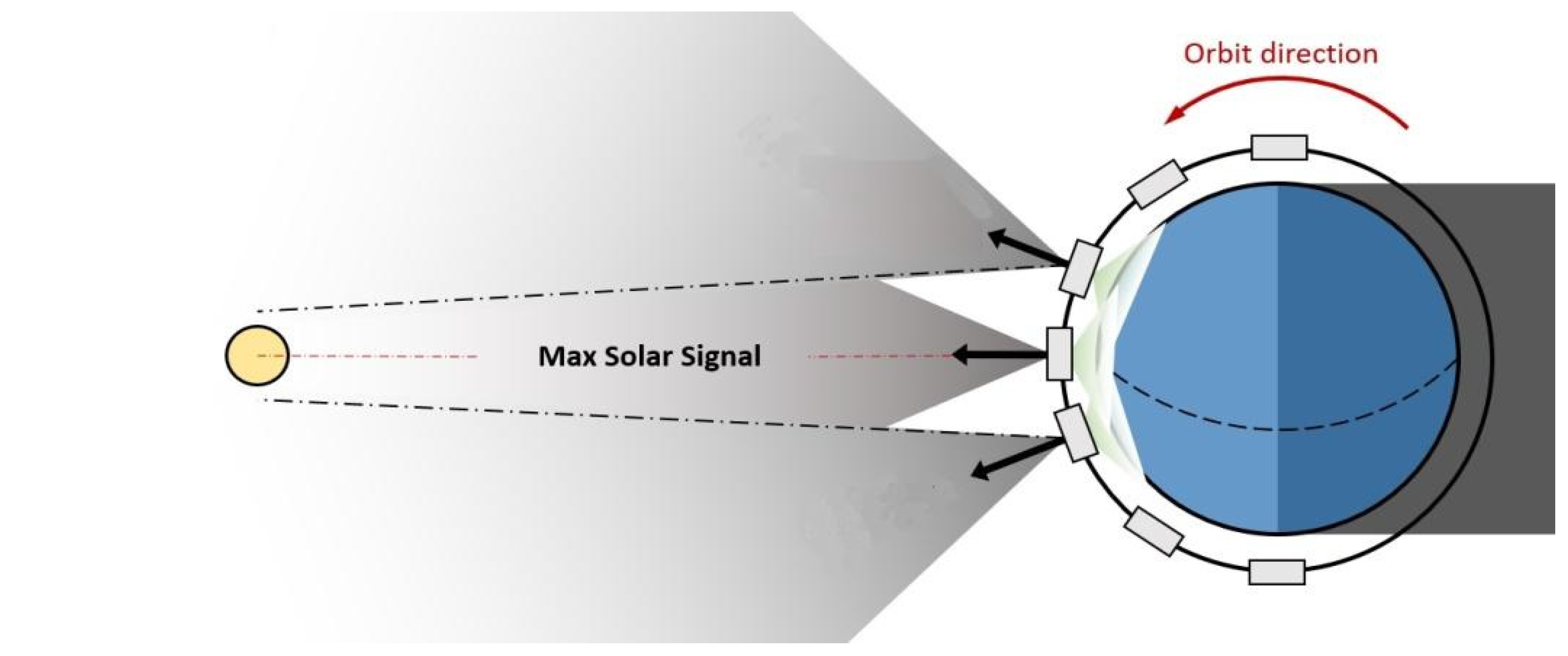
Figure 9. The architecture is constructed around the zenith and nadir payload antennas and the need to maximize solar exposure in a noon-midnight orbit.
The payload consists of two antennas and an S-band receiver with software-defined radio (SDR) architecture. A deployable helical antenna acts as the primary antenna recording the microwave activity of the Sun on the desired frequencies while the secondary wideband patch antenna is used to detect background radio noise from RFI and thermal Earth emissions on the same frequencies.
The ADCS, which stabilizes the spacecraft against external perturbations, consists of three reaction wheels, a 3-axis magnetometer, two IR Earth Horizon Sensors, three electromagnets, and an astronomy data and computing services computer. It maintains the nadir orientation of the secondary antenna throughout the orbit and points the helical antenna at the Sun with required pointing accuracy during solar observations. A global navigation satellite system (GNSS) antenna and receiver offers <10 m positioning accuracy by receiving GPS L1 and GALILEO E1 signals. GPS will be sampled once per second and used for post-processing of F10.7 data and generation of a global microwave emissions model.
Payload and telemetry, tracking and command (TT&C) data are downlinked using a nadir S-band patch antenna identical to the payload secondary patch antenna. The bandwidth of the payload antenna cannot be extended to reach the 2250 MHz frequency of the ground station unless customized at a notable expense. A dual UHF/VHF dipole antenna with a complimentary UHF/VHF transceiver is used for TT&C uplink via the VHF frequencies. UHF frequencies could be used to downlink part of the solar observation data in the event of failures within the S-band system.
The satellite subsystems are supported by an onboard computer and electrical power system (EPS). Power is generated by gallium arsenide (GaA) triple-junction solar cells laid out on three 1U body-mounted solar panels and four double-sided 3U deployable solar panels. A 22.4 W⋅h Li-Ion battery pack provides power during an eclipse. The battery pack and a heater are integrated into the EPS. Satellite thermal control is achieved passively with aluminized kapton surface coatings.
RMCSat does not require a propulsion system as the satellite does not need to maintain its original orbit nor carry out orbital maneuvers during the mission. External perturbations experienced by RMCSat over the course of its mission are not anticipated to be large enough to disrupt the orbit to the point where the mission is impacted.
The estimated mass budget for the Cubesat is given in Table 5. Margins are assigned to components depending on their flight heritage (5%) and technological readiness (10%), customization (20%), and in-house manufacturing (25%). The total estimated mass with margins sits comfortably within the 4kg limit for a 3U Cubesat.

4.1. Payload and Data Generation

The primary antenna is a deployable helical wire antenna with 40 turns (63 cm long), a diameter of 3.2 cm, a pitch of 1.7 cm, and a thickness of 1 mm. A deployable antenna of this length can realistically be deployed from a 1 U volume of the satellite. Such an antenna has been analyzed using MATLAB Antenna Designer and offers gain directivity of 17 dBi at 2800 MHz, and 16.7 dBi at 2695 MHz [18]. A ground-based field experiment using a small parabolic antenna successfully demonstrated that an antenna with a gain of 14 dBi is sensitive enough to detect small variations in the F10.7 solar flux to less than 1% of the peak value [18], meeting the DRAO standard for system accuracy [1]. Figure 10 presents the directive gain pattern for the 40-turn helical antenna at 2800 MHz and 2695 MHz.
Possible orientations of the antenna relative to the satellite body were investigated with regards to the impact of each orientation on the gain differential ( Δ G ) of the antenna, defined as the difference between the main beam gain and the average backlobe gain. A number of antenna orientations were tested with respect to the satellite body axes and the optimal orientation is shown in Figure 9 [18]. In addition to optimizing Δ G , this orientation increases nadir surface area on the satellite for the secondary and communications patch antennas and creates a smaller cross-sectional area for drag forces enabling longer orbital maintenance.
A microstrip patch antenna array was investigated as an alternate primary payload antenna but was found to be unsuitable for this radiometry application due to suboptimal array spacing options constrained by CubeSat geometry and a reduced solar power generation area. However, the wider beam of an individual patch antenna is ideal for the secondary payload antenna to record the terrestrial thermal emissions. A modified Commercial-Off-The-Shelf (COTS) S-band patch antenna shifts the two standard commercial frequency bands offered to match the desired 2695 MHz and 2800 MHz [27].
Operationally, the payload takes measurements on three channels, 2695 MHz, 2785 MHz, and 2815 MHz. For each channel, a corresponding secondary antenna measurement is required; therefore the six channels are monitored (Table 6).
The output from the antenna is a direct current voltage that is directly proportional to the antenna temperature, and hence the power of the signal received by the radiometer. If background noise flux and any internally generated system noise remain constant, the increase in voltage measured when an antenna points at the Sun will be directly proportional to the microwave flux density of the Sun.
A multi-channel SDR gives the mission the flexibility to adjust properties like observation frequencies, bandwidth, and modulation from the ground. The generic processor hardware in conjunction with programmable software enables digital replication of electronic radio receiver circuits. If there is too much interference from RFI, the bandwidths or modulations can be altered.
The minimum observation time is calculated using,
t o b s = θ 360 P ,
where P is the orbit period and θ in this case is the antenna beamwidth between first nulls (BWFN). Since 2695 MHz and 2800 MHz channels are monitored concurrently, the larger BWFN determines the observation time required to ensure that the nulls of both frequency patterns are captured, enabling accurate determination of the peak flux values. Table 7 shows the minimum observation time based on BWFN.
The payload has a sample rate of 1000/s, which is averaged and logged at one-second intervals. Allowing for an additional 40% margin for the minimum observation time of 752 s and 50 bytes per line of data, Table 8 shows the observational data generated by the payload. The TT&C downlink data containing diagnostic information is estimated to be 1 Mb as is the uplink command data. GPS sampling at 1 Hz is estimated at 10 Mb. Thus the total amount of data that needs to be downlinked each day is 27.9 Mb. If only the solar observations and TT&C information are downlinked, the data are 5.75 Mb.

4.2. Communications and Link Budget

The communications plan relies on the use of a single ground station at RMC in Kingston, Ontario, Canada, and a store and forward mode of data collection. The ground station consists of a 3.0 m parabolic S-band antenna with a high rate S-band receiver and a Yagi antenna and associated transceiver for UHF and VHF signals. Other locations with similar S-band downlink and UHF/VHF capabilities are suitable if required as the geographical location of the ground station is not critical to the mission.
The satellite passes over the RMC ground station four to six times each day, with a mean access time of 573 s as determined using the Systems Tool Kit software. The operations plan reserves a 25% error margin given 573 s is the mean access value, thus 430 s is used for rate calculations. A minimum downlink data rate of 62.6 kbps is required if the downlink is completed during one pass. This rate sits well within the S-band system capabilities. The maximum VHF uplink rate of the ground station is 1.2 kbps. Consequently, the estimated 1 Mb of TT&C data is uplinked over two passes resulting in a rate of 1.16 kbps.
If the UHF system is required due to S-band failure, only TT&C data and solar observations can be downlinked (5.75 Mb per day). To achieve an adequate link margin of 3.0 dB for the UHF system (Table 9), the maximum data rate is limited to 3.5 kbps. Four passes are required to downlink the data using the UHF system at a rate of 3.3 kbps.
Link margin calculations are presented in Table 9. The link margins of the S-band downlink, VHF uplink, and UHF downlink are calculated as 13.96 dB, 17.37 dB, and 3.06 dB, respectively.
The storage capacity of the onboard computer is 4 GB, with the option of up to 32 GB. This offers 148 days, or up to 1188 days, of storage before payload data must be overwritten. Additional storage exists within the S-band transmitter, up to 32 GB. If the UHF system is required for downlink, successive passes can be used to downlink more observational data once the daily data are received.

4.3. Power Budget

There are four different power modes in which the satellite operates: Solar Observations, Solar Cruise, Eclipse Cruise, and Communication. Table 10 shows the power budget for the different modes. The peak power usage occurs during Communication, consuming up to 13.7 W.
Communication occurs during one daylight passes of the ground station per day. As shown in Table 11, the average orbital power necessary is 9.4 W, for which the solar panels are designed to meet. Additional power can be drawn from the batteries during eclipse and peak power operations.
Gallium Arsenide (GaA) triple-junction solar cells offer a production efficiency of 30% and performance degradation of 0.5% per year [28]. Based on these solar cells, the design orbital parameters, and an average solar incident angle of 45°, the solar array power required is 18.0 W, or an array area of 864 cm2. Using a cell size of 26 cm2 and two cells per 1U, 17 1U panels would be required. While the deployable arrays and body-mounted cells provide 28U of the area and the capacity to generate 30.3 W, only 18U of cells is exposed to the Sun at any one time. The 18.0 W design provides a 20% power margin which allows for poor solar angles such as those at the terrestrial poles and for any cell failures.
The proposed COTS EPS offers integrated batteries that have a capacity of 22.4 W⋅h and a battery heater for eclipse conditions. This size is more than sufficient to meet the required battery capacity of 12.4 Wh for RMCSat in full eclipse (7.6 W).

4.4. Thermal Control

The thermal control design of RMCSat seeks to keep the satellite equipment within temperature limits with a 5 °C buffer. The temperature ranges of the satellite components are given in Table 12. The thermal operating range of the RMCSat is −15 °C to 55 °C, limited by the ADCS and UHF communication systems. The integrated battery heater within the electrical power system allows a greater temperature range for the batteries than is typically found.
A first-order analysis of the thermal environment and temperature indicates that thermal control does not pose an issue for the mission. The sources of external heat considered include the direct solar energy of the Sun, solar energy that is reflected off the Earth, thermal energy radiated from Earth, and atmospheric drag heating [28]. The internal heat sources are derived from heating caused by spacecraft components, which are taken as the lowest and highest power levels of the satellite operations. The extreme temperature range derived from the analysis is −6.8 °C to 64.8 °C, which sits above the maximum temperature of some components. However, if a quarter millimeter layer of aluminized kapton is used, it lowers the temperatures to −7.8 to 50.7 °C, within the thermal operating range of RMCSat.

5. Future Development Considerations

Further development of RMCSat rests in detailed assessments of the payload antennas as satellite subsystems do not present any problems at this stage. Securing a suitable launch is another critical element as the final launch orbit dictates whether design changes to the CubeSat platform or operations plan are necessary.
The radio technology of the helical antenna shows that it is suitable for the CubeSat mission, however, the physical characteristics of the antenna require detailed engineering analysis and design. The issue of antenna rigidity and potential distortion during spacecraft maneuvers must be addressed in subsequent design discussions. Similarly, the deployable nature of the antenna means that it must deploy reliably and achieve the correct geometry after deployment. Any change in the geometry through compression or lateral deformation alters the pitch angle and spacing of the wire turns, and hence the gain pattern of the antenna. A stabilization mechanism, such as a deployable tape, has been suggested to improve rigidity without affecting antenna performance [29].
The beamwidth of the secondary patch antenna also requires further analysis. An HPBW of 70 degrees is provided by the antenna under consideration, but additional investigation is needed to confirm if it is sufficiently broad to capture and replicate the exposure field of the primary antenna [27].
Finally, the proposed CubeSat design is founded on a noon-midnight SSO. If this orbit, or one close to it, is not achievable, the complexity of the solar observations increases significantly along with the layout of the two payload antennas as discussed in Section 3. The inclusion of any consequential physical shielding for the primary antenna also has implications for the mass budget of the satellite.

6. Conclusions

RMCSat is a 3U CubeSat mission designed to assess the feasibility of obtaining space-based F10.7 solar flux measurements from LEO. As a technology demonstrator, it will enable the real-world assessment of the utility of space-based miniaturized solar microwave radiometry; however, it will also provide valuable dual-frequency comparative measurements to the existing F10.7 dataset. It does so by monitoring three microwave frequencies, 2695 MHz, 2785 MHz, 2815 MHz using the same calibration standard to allow for signal comparison and true scaling of measurements. Measurements of F10.7 are captured by two payload antennas both in and outside of the DRAO operation window with sufficient accuracy to complement existing operations and increase temporal and geographical coverage.
The mission concept and preliminary design of the satellite described here demonstrate the feasibility to proceed to the next phase of development. The satellite subsystems and system budgets are viable. Elements of the next design phase include a more detailed assessment of the payload antennas and an investigation of achievable launch orbits within the desired mission timeframe. As the development of RMCSat proceeds, it continues to provide valuable hands-on space mission design, operations, and solar monitoring experience to both graduate and undergraduate university students at RMC.

Author Contributions

M.V. carried out the initial research. H.T. refined the mission parameters and wrote the paper. L.S. and R.V. supervised the research. All authors have read and agreed to the published version of the manuscript.

Funding

Canadian Defence Academic Research Program.

Institutional Review Board Statement

Not applicable.

Informed Consent Statement

Not applicable.

Data Availability Statement

Not applicable.

Conflicts of Interest

The authors declare no conflict of interest.

References

  1. Tapping, K.F. The 10.7 cm Solar Radio Flux (F10.7). Space Weather 2013, 11, 394–406. [Google Scholar] [CrossRef]
  2. Kane, R. Correlation of Solar Indices with Solar EUV Fluxes. Sol. Phys. 2002, 207, 17–40. [Google Scholar] [CrossRef]
  3. Liu, L.; Wan, W.; Ning, B.; Pirog, O.M.; Kurkin, V.I. Solar Activity Variations of the Ionospheric Peak Electron Density. J. Geophys. Res. 2006, 111, A8. [Google Scholar] [CrossRef]
  4. Schunk, R.W.; Nagy, A.F. Ionospheres: Physics, Plasma Physics, and Chemistry. Cambridge Atmospheric and Space Science Series; Cambridge University Press: Cambridge, UK, 2000. [Google Scholar]
  5. Lilensten, J.; de Wit, T.D.; Kretzschmar, M.; Amblard, P.-O.; Moussaoui, S.; Aboudarham, J.; Auchère, F. Review on the Solar Spectral Variability in the EUV for Space Weather Purposes. Ann. Geophys. 2008, 26, 269–279. [Google Scholar] [CrossRef] [Green Version]
  6. Belehaki, A.; Stanislawska, I.; Lilensten, J. An Overview of Ionosphere–Thermosphere Models Available for Space Weather Purposes. Space Sci. Rev. 2009, 147, 271–313. [Google Scholar] [CrossRef]
  7. Vallado, D. Fundamentals of Astrodynamics and Applications; Springer: New York, NY, USA, 2007. [Google Scholar]
  8. F 10.7 cm Radio Emissions. Space Weather Prediction Center, National Oceanic and Atmospheric Administration. Available online: https://www.swpc.noaa.gov/phenomena/f107-cm-radio-emissions (accessed on 23 October 2020).
  9. NASA. Atmospheric Electromagnetic Transmittance or Opacity. Image, Public Domain. Available online: https://commons.wikimedia.org/wiki/File:Atmospheric_electromagnetic_transmittance_or_opacity.jpg (accessed on 1 September 2021).
  10. Du, Z. Forecasting the Daily 10.7 cm Solar Radio Flux Using an Autoregressive Model. Sol. Phys. 2020, 295, 125. [Google Scholar] [CrossRef]
  11. Henney, C.J.; Toussaint, W.A.; White, S.M.; Arge, C.N. Forecasting F10.7 with Solar Magnetic Flux Transport Modeling. Space Weather 2012, 10, S02011. [Google Scholar] [CrossRef]
  12. Devos, A.; Verbeeck, C.; Robbrecht, E. Verification of Space Weather Forecasting at the Regional Warning Center in Belgium. J. Space Weather Space Clim. 2014, 4, A29. [Google Scholar] [CrossRef]
  13. Hey, J.S. The Evolution of Radio Astronomy; Science History Publications: New York, NY, USA, 1973. [Google Scholar]
  14. Yaya, P.; Hecker, L.; de Wit, T.D.; Fèvre, C.L.; Bruinsma, S. Solar Radio Proxies for Improved Satellite Orbit Prediction. J. Space Weather Space Clim. 2017, 7, A35. [Google Scholar] [CrossRef] [Green Version]
  15. Kennewell, J.A. RSTN Solar Radio Telescopes (Discrete Frequency) and Data. 2008. Available online: http://www.deepsouthernskies.com/LSO/RSTN.pdf (accessed on 1 August 2021).
  16. Acebal, A.O.; Sojka, J.J. A Flare Sensitive 3 h Solar Flux Radio Index for Space Weather Applications. Space Weather 2011, 9, S07004. [Google Scholar] [CrossRef] [Green Version]
  17. Ahluwalia, H.S. The Descent of the Solar Cycle 24 and Future Space Weather. Adv. Space Res. 2016, 57, 710–714. [Google Scholar] [CrossRef]
  18. Vreugdenburg, M. The RMCSat Solar Flux Mission. Master’s Thesis, Royal Military College of Canada, Kingston, Canada, 20 July 2020. Available online: https://www.researchgate.net/publication/356084586_Vreugdenburg_2020_-_The_RMCSat_Solar_Flux_Mission (accessed on 21 November 2021). [CrossRef]
  19. International Telecommunication Union. Recommendation ITU-RM.1464-2: Characteristics of Radiolocation Radars, and Characteristics and Protection Criteria for Sharing Studies for Aeronautical Radionavigation and Meteorological Radars in the Radio Determination Service Operating in the Frequency Band 2700–2900 MHz. 2015. Available online: https://www.itu.int/rec/R-REC-M.1464/en (accessed on 11 July 2020).
  20. Electronic Communications Committee (ECC) within the European Conference of Postal and Telecommunications Administrations (CEPT). The European Table of Frequency Allocations and Applications in The Frequency Range 8.3 Khz to 3000 Ghz (ECA Table). March 2019. Available online: https://www.google.com/url?sa=t&rct=j&q=&esrc=s&source=web&cd=&ved=2ahUKEwj1lJLfvar0AhUcl2oFHV-1C3oQFnoECAgQAQ&url=https%3A%2F%2Fdocdb.cept.org%2Fdownload%2F2051&usg=AOvVaw3ehiyy0EgEPCqw7m_wVU4V (accessed on 20 July 2020).
  21. National Telecommunications and Information Administration. Federal Government Spectrum Compendium: Federal Government Spectrum Use Reports 225 MHz–7.125 GHz. 2015. Available online: https://www.ntia.doc.gov/page/federal-government-spectrumuse-reports-225-mhz-7125-ghz (accessed on 22 October 2019).
  22. Spectrum Management and Telecommunications, Innovation, Science and Economic Development Canada. Canadian Table of Frequency Allocations (2018 Edition). April 2018. Available online: https://publications.gc.ca/site/eng/9.856955/publication.html (accessed on 23 November 2019).
  23. Condon, J.J.; Ransom, S.M. Essential Radio Astronomy; Princeton University Press: Princeton, NJ, USA, 2016. [Google Scholar]
  24. Tiuri, M.E. Radio-Telescope Receivers. In Radio Astronomy; Kraus, J.D., Ed.; McGraw-Hill: New York, NY, USA, 1966; pp. 236–293. [Google Scholar]
  25. Adcole Maryland Aerospace, Inc. MAI-400: 1/2U CubeSat ADACS. 2017. Available online: https://satcatalog.s3.amazonaws.com/components/87/SatCatalog_-_Adcole_Maryland_Aerospace_-_MAI-400_-_Datasheet.pdf (accessed on 8 February 2021).
  26. IADC Steering Group and Working Group 4. IADC-02-01 IADC Space Debris Mitigation Guidelines (Revision 2). Inter-Agency Space Debris Coordination Committee. March 2020. Available online: https://www.google.com/url?sa=t&rct=j&q=&esrc=s&source=web&cd=&cad=rja&uact=8&ved=2ahUKEwjC7diCwKr0AhWlkWoFHbmBDRAQFnoECAYQAQ&url=https%3A%2F%2Forbitaldebris.jsc.nasa.gov%2Flibrary%2Fiadc-space-debris-guidelines-revision-2.pdf&usg=AOvVaw1zvdoejU5R6ipRxTp8cqk7 (accessed on 21 November 2021).
  27. Datasheet Wideband S-band Antenna, Endurosat. 2020. Available online: https://www.endurosat.com/cubesat-store/cubesat-antennas/s-band-antenna-wideband/#contact-modal (accessed on 24 August 2021).
  28. Wertz, J.; Everett, D.; Puschell, J. Space Mission Engineering: The New SMAD; Microcosm Press: Portland, OR, USA, 2011. [Google Scholar]
  29. O’Neil, G.; (Helical Communication Technologies, Rockledge, FL, USA). Personal communication, 2019.
Figure 1. Absorption windows for wavelengths within the Earth’s atmosphere. While the 10.7 cm radiation falls within a window of atmospheric transparency for transmission, the atmosphere is opaque to EUV wavelengths (10 to 120 nm) due to neutral particle absorption. The transmission of wavelengths more than 10 m is increasingly affected by charged particles in the ionosphere, with the minimum frequency of penetration governed by the local total electron content (TEC). Adapted from [9].
Remotesensing 13 04754 g001
Figure 2. An antenna directive gain elevation pattern for a simple helical antenna, with beam terminology annotated. Elevation is in degrees, gain in dBi. The half-power beamwidth (HPBW) defines the plane angle at which the gain of the main beam has reduced by 50% (3 dBi).
Remotesensing 13 04754 g002
Figure 3. The effect of main beam gain on the measured F10.7 value, for F10.7 = 100 sfu. (a) The full main beam response. (b) A close-up of the central beam region. If the Sun passes through the main beam off-boresight, the measured F10.7 is lower than the actual value, as shown by the blue curve. The red line indicates the point at which the measured solar flux density is 1% less than the actual value, corresponding to an antenna gain reduction of 0.043 dBi.
Remotesensing 13 04754 g003
Figure 4. Sun Synchronous Orbit Comparison. (a) In a dawn/dusk orientation, the satellite maintains near-constant access to the Sun. Note that the tilt of the satellite at the extreme north and south points on the orbit in this diagram is greatly exaggerated. (b) In a noon/midnight orbit the satellite spends minimal time in Sun, with almost half of the orbit in eclipse. The arrows indicate antenna boresight.
Remotesensing 13 04754 g004
Figure 5. Pointing regime examples, depicting (a) sun-tracking and (b) zenith pointing options. (a) The satellite orients the antenna towards the Sun as soon as a line of sight is possible, and maintains tracking for the duration of the dayside orbit sector. (b) The antenna maintains a fixed zenith angle with respect to the Earth. The grey beam represents the primary antenna main lobe.
Remotesensing 13 04754 g005
Figure 6. The proposed payload operations cycle for a noon/midnight SSO, shown with the Sun at zero declination. The grey zenith-pointing beam is the primary payload antenna, the green lower beam represents the secondary antenna for Earth flux sensing. The timing of measurement operations ensures that the Sun passes through the first null of the antenna beam at the beginning and end of each measurement. This example depicts a local noon descending node, however, the direction of noon equatorial crossing is not important for data collection operations.
Remotesensing 13 04754 g006
Figure 7. (a) The satellite alignment for a noon crossing orbit. The direction of satellite travel is on the page. (b) Simulation of the effect of a 15° tilt required to maintain solar alignment for an SSO one hour offset from noon. The dashed line represents local noon, the green beam is indicative of the effect on a secondary antenna.
Remotesensing 13 04754 g007
Figure 8. Concept diagram of RMCSat mission.
Remotesensing 13 04754 g008
Figure 9. RMCSat architecture diagram. The satellite is a 3U CubeSat (10 × 10 × 30 cm) with deployable solar panels and payload antennas.
Remotesensing 13 04754 g009
Figure 10. Approximate directivity for a 40-turn helical antenna at 2695 MHz and 2800 MHz using the MATLAB Antenna Designer. The antenna is shown within a box representing the deployment module. At 2800 MHz, a half-power beamwidth (HPBW) of 23° and directivity of 17 dBi is achieved. At 2695 MHz, the same geometry produces an HPBW of 25° and directivity of 16.7 dBi.
Remotesensing 13 04754 g010
Table 1. Primary mission objectives of RMCSat.
MSN-OBJ-01Obtain space-based F10.7 solar flux measurements, increasing temporal coverage over 24 h and geographical coverage.
MSN-OBJ-02Monitor 2800 MHz and 2695 MHz using the same calibration standard to allow for signal comparison and true scaling of measurements. Since 2695 MHz is an interference-free protected channel, it will also be compared against 2800 MHz to determine if the 2800MHz channel is experiencing narrowband RFI unique to that channel, or broadband solar/internal interference.
MSN-OBJ-03Produce measurements of F10.7 both in and outside of the DRAO operation window with sufficient accuracy to complement existing operations.
MSN-OBJ-04Provide hands-on space mission and solar monitoring experience to a new generation of university students. The project will provide the basis for approximately five graduate theses in Physics and Engineering, while providing undergraduate Space Science students with mission design, satellite construction, and space operations training. RMC faculty mentored undergraduate and graduate students in the development of the Automatic Dependent Surveillance-Broadcast payload that flew on the CanX-7 CubeSat. Currently, RMC Space Mission Analysis and Design courses form the cornerstone of the International Space Mission Training Program, a Collaborative Research and Training Experience sponsored by the Natural Sciences and Engineering Research Council of Canada.
Table 2. Secondary mission objectives of RMCSat.
MSN-OBJ-05Improve the current understanding of the correlation between solar flux observations wavelengths.
MSN-OBJ-06Assess the suitability of using 2695 MHz data generated by the RSTN as a scaled substitute for F10.7.
Table 3. CubeSat lifetimes, in years, modeled for different altitudes and drag coefficients ( c D ) using the Systems Tool Kit Satellite Lifetime tool.
Altitude c D = 2.2
Lifetime (Years)
c D = 2.5
Lifetime (Years)
c D = 3
Lifetime (Years)
500 km10.27.54.8
550 km23.418.514.6
600 km51.147.237.7
Table 4. Proposed payload operations cycle for an average noon/midnight SSO, commencing at the equator in eclipse.
Operation ModeConditionTime (min)Cumulative Time (min)
Eclipse CruiseEclipse17.817.8
Solar CruiseDaylight14.131.9
Communication (2 orbits per day)Daylight7.239.1
Solar Observations (min. 12.5 min)Daylight17.556.6
Solar Cruise Daylight21.377.8
Eclipse CruiseEclipse17.895.6
Table 5. Mass budget for RMCSat.
ComponentMass (g)MarginMass with Margin (g)
Primary payload antenna30025%375
Secondary payload antenna11510%127
Payload receiver18010%198
Electrical power system1905%200
S-band communication patch antenna11510%127
S-band transmitter1805%189
UHF antenna905%95
UHF transceiver755%79
Onboard Computer765%80
Attitude Determination and Control6945%729
GPS antenna2010%22
GPS receiver10610%117
Solar Panels31220%374
Cubesat Structure29620%355
Wire harness40025%500
Total3149 3342
Table 6. Data collection channels for RMCSat.
ChannelAntenna FeedFrequencyBandwidth
1Primary2695 MHz7 MHz
2Primary2785 MHz20 MHz
3Primary2815 MHz20 MHz
4Secondary2695 MHz7 MHz
5Secondary2785 MHz20 MHz
6Secondary2815 MHz20 MHz
Table 7. Minimum observation times required for 2695 MHz and 2800 MHz based on antenna BWFN.
Property2695 MHz2800 MHz
BWFN47.2°44.1°
Minimum observation time 752 s703 s
Table 8. Data generation for RMCSat payload. An additional 40% margin is added to the minimum observation time of 752 s and 50 bytes is assumed per line of data recorded.
Solar ObservationsFull Orbit Observations
Time of observation (seconds)1052.85738.99
Number of lines per second66
Lines of data in one orbit 631734,434
Lines of data per day95,099518,400
Data generated per orbit (byte)315,8401,721,697
Data generated per day (byte)4,754,94425,920,000
Data generated per day (Mb)4.7525.92
Table 9. RMCSat Communications Link Margin. The margin is determined using the calculated Eb/No less the required Eb/No and System Losses.
ParameterDownlink S-Band (dB)Uplink VHF (dB)Downlink UHF (dB)
Effective isotropic radiated power26.6010.30−0.40
Space loss168.14144.37153.89
Receiver antenna gain34.5010.7
Receiver system noise temperature28.4528.4528.45
Data Rate66.34
(4.3 Mbps)
30.79
(1.2 kbps)
35.44
(3.5 kbps)
Attenuation loss (1 degree elevation)1.720.020.16
Calculated Eb/No25.0635.2720.38
Required Eb/No9.616.416.4
Polarization mismatch0.30.30.3
Antenna pointing0.20.20.2
System implementation111
System losses1.51.51.5
Link Margin
(Calculated Eb/No-Required Eb/No-System Losses)
13.96017.373.06
Table 10. Power budget for RMCSat. Power consumption for the UHF is for the receiver only. 4W are consumed during UHF transmission, but this value would replace S-band transmitter consumption.
ComponentOperation Mode (W)
Solar ObservationsSolar CruiseEclipse CruiseCommuni-cations
Primary payload antenna0.150.150.150.15
Secondary payload antenna0.050.050.050.05
Payload receiver2.502.502.502.50
Electrical power system 0.900.090.090.09
S-band communication patch antenna0.050.050.050.05
S-band transmitter0.420.420.427.50
UHF antenna0.040.040.040.04
UHF transceiver0.000.000.000.48 *
Onboard Computer 0.40 0.40 0.40 0.40
ADCS 2.051.101.101.10
GNSS antenna0.050.050.050.05
GNSS receiver1.301.301.301.30
Integrated battery heater 0.000.001.400.00
Battery Charge (when in daylight)0.005.000.000.00
TOTAL 7.911.27.613.7
Table 11. Average orbital power requirements for an orbit that include Communication.
Operating ModeTime in One Orbit (Minutes)Percent of Orbit (%)Mode Power Demand (W)Power Used (W)
Communication7.170.0813.71.0
Solar Cruise35.330.3711.24.1
Eclipse Cruise35.600.377.62.8
Solar Observations17.500.187.91.4
TOTAL95.601.00average power 9.4
Table 12. Temperature ranges for proposed RMCSat components. * Temperature range of the primary antenna is estimated pending thermal testing.
ComponentsTemperature Range with 5 °C Buffer (°C)
Primary payload antenna *−15 to 55
Secondary payload antenna−35 to 120
Payload receiver−25 to 65
Electrical power system−35 to 75
S-band communication patch antenna−35 to 120
S-band transmitter−25 to 65
UHF antenna−15 to 55
UHF transceiver−15 to 55
Onboard Computer−20 to 55
ADCS−15 to 55
GNSS antenna−25 to 65
GNSS receiver−35 to 80
Solar Panels−45 to 145
Publisher’s Note: MDPI stays neutral with regard to jurisdictional claims in published maps and institutional affiliations.

