Article

Joint Radar-Communications Exploiting Optimized OFDM Waveforms

1
Department of Electrical and Computer Engineering, Temple University, Philadelphia, PA 19122, USA
2
Department of Electrical Engineering, Wright State University, Dayton, OH 45435, USA
*
Author to whom correspondence should be addressed.
Remote Sens. 2021, 13(21), 4376; https://doi.org/10.3390/rs13214376
Submission received: 21 September 2021 / Revised: 23 October 2021 / Accepted: 26 October 2021 / Published: 30 October 2021

Abstract

:
We propose novel Joint Radar-communication spectrum sharing strategies exploiting orthogonal frequency-division multiplexing (OFDM) waveforms that concurrently achieve the objectives of both radar and communication systems. An OFDM transmitter is considered that transmits dual-purpose OFDM subcarriers such that all the subcarriers are exploited for the primary radar function and further exclusively allocated to the secondary communication function serving multiple users. The waveform optimization is performed by employing mutual information (MI) as the optimization criterion for both radar and communication operations. For the purpose of radar performance optimization, we consider the MI between the frequency-dependent target response and the transmit OFDM waveforms. On the other hand, communication system performance is evaluated in terms of the MI between the frequency-dependent communication channels of communication users with the transmit OFDM subcarriers. These optimization objectives not only enable the transmit power allocation of the OFDM subcarriers, but also govern the subcarrier distribution among the communication users. Two resource optimization scenarios are considered, resulting in radar-centric and cooperative resource allocation strategies that exploit convex and mixed-integer linear programming optimization problems for power allocation and subcarrier distribution, respectively. We further present a chunk subcarrier allocation approach that applies to both optimization strategies to reduce the computational complexity with a trivial performance loss. Simulation results are presented to illustrate the effectiveness of the proposed strategies.

Graphical Abstract

1. Introduction

Wireless spectrum sharing has attracted significant attention from researchers due to the ever-increasing demand for spectral resources for existing and emerging applications [1,2,3,4,5,6]. Modern wireless communication systems require extensive expansion in allocated spectral resources in order to enhance data rates and quality of service. Emerging technical fields, such as the Internet of Things, call for new dedicated spectral allocations to bring new products onto the market. The problem of spectral congestion has traditionally been addressed by enhancing the spectral efficiency using cognitive radio [7] and cognitive radar [8]. On the other hand, recent efforts towards spectrum-efficient systems have mostly focused on spectrum sharing approaches that enable multiple disparate applications within the same spectrum bands [9,10,11,12,13,14,15,16,17,18,19,20,21,22,23,24,25,26,27,28,29,30,31].
There are two main classes of radar–communication spectrum sharing strategies that have been considered in the literature. The first type consists of co-existing radar and communication systems in the same spectrum bands where the mutual interference is mitigated via exploiting extensive cooperation and/or information sharing between the two systems. On the other hand, the second strategy enables Joint Radar-communication (JRC) by utilizing dual-purpose waveforms that serve the objective of both subsystems. The information embedding in JRC systems is enabled either by embedding communication information in radar waveforms or by dedicating separate waveforms to radar and communications [1,2,3,5,9,10,11,12,13,14,15,17,18,19,20,21,22,23,24,25,26,28,29,30,31].
The basic principle of a JRC system is to transmit waveforms that simultaneously achieve both radar and communication objectives by using the same physical platform as illustrated in Figure 1. Such systems achieve their objectives either by employing spatial multiplexing using smart antenna arrays [4,12,13,14,15,20], waveform diversity [1,2,3,9,18,23,25,26,28,32], or their combination [5,17,19,21,22,24]. JRC systems are inherently robust against mutual interference since both the radar and communication systems exploit the same waveforms. However, waveform optimization still remains a challenge in such systems especially if the waveforms have to be designed in real time.
To perform optimized waveform design, mutual information (MI) has been extensively used in the literature as a quantitative performance measure for both radar and communication systems [18,33,34,35,36]. For radar systems, MI maximization is directly linked to maximizing the probability of detection while maintaining a constant false alarm rate [33]. On the other hand, for communication systems, MI maximization is analogous to maximizing the channel capacity for the systems [35]. As such, we adopted MI as a quantitative measure to evaluate the performance of JRC systems. The convex nature of MI maximization makes it better for performance analysis and optimization than nonconvex measures such as the Cramer–Rao bound and the probability of detection.
Our contributions in this paper are summarized as follows:
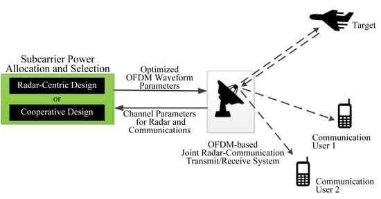
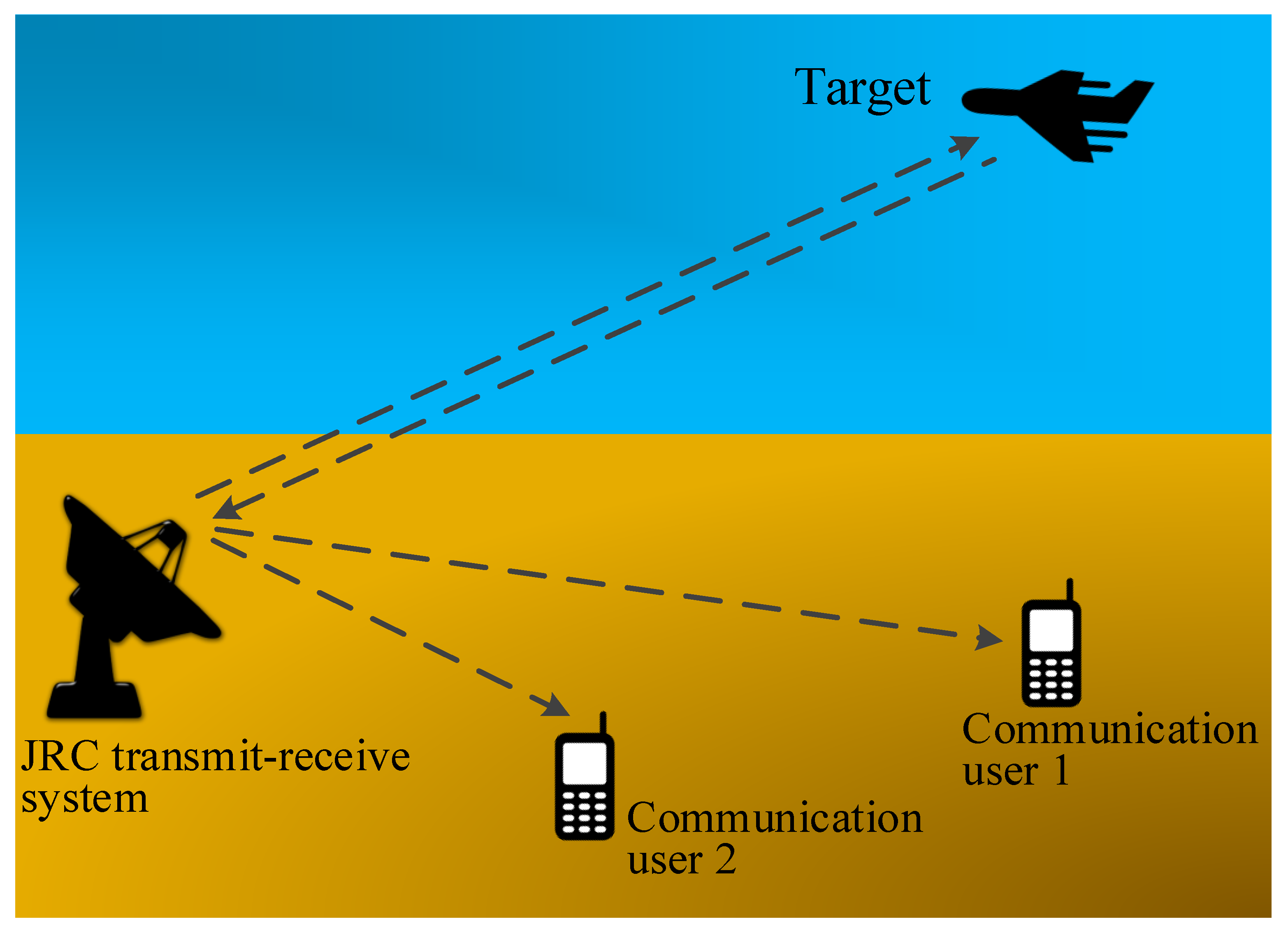
  • We propose a method for exploiting OFDM waveforms in JRC operation where all the subcarriers are used for the primary radar operation. At the same time, the subcarriers are further used for secondary communications and are distributed to multiple communication users in a mutually exclusively manner;
  • Considering frequency-selective radar target characteristics and communication channels, we derive the mathematical formulation of the MI for both radar and communication subsystems;
  • We devise solutions to the problem of subcarrier power allocation, as well as subcarrier distribution by exploiting the MI for both the radar and communication subsystems. In this context, we develope two optimization strategies respectively implementing radar-centric and cooperative JRC system designs. We show that the optimization strategy for power allocation is a convex optimization problem, whereas the optimization for the subcarrier distribution for multiple communication users is a mixed-integer linear programming (MILP) problem;
  • In order to reduce the computational complexity of the optimization problems, we introduce chunk power allocation and subcarrier assignment techniques. These techniques group close subcarriers in the form of chunks, leading to a reduction in the computational complexity without noticeable performance loss in both the radar and communication subsystems.
The paper is organized as follows. The system model of the JRC system exploiting OFDM waveforms is described in Section 2. In Section 3, we derive the mathematical formulations of the MI for the radar and communication subsystems by considering frequency-selective channels. Section 4 discuses optimal power allocation and subcarrier assignment for radar-centric and cooperative JRC system designs. Section 5 discusses the power allocation and subcarrier assignment for the chunk of subcarriers. Simulation examples are provided in Section 6 to demonstrate the effectiveness of the proposed methods. Finally, conclusions are drawn in Section 7.
Notations: We use lowercase (uppercase) bold characters to describe vectors (matrices). In particular, I K stands for the K × K identity matrix, whereas 1 K and 0 K respectively represent the K × 1 vectors of all ones and zeros. The operations ( · ) T and ( · ) H denote the transpose and conjugate transpose, respectively, while the symbol ∗ denotes the convolution operator. The notation h ( x ) denotes the differential entropy of x , I ( x ; s ) denotes mutual information between x and s , whereas E · and log ( · ) stand for statistical expectation and the logarithm of base two, respectively. Finally, diag ( x ) denotes the diagonal matrix whose main diagonal is comprised of the entries from x, while tr ( · ) denotes the trace of a matrix.

2. System Model

Consider a JRC system consisting of a single-antenna transmitter that transmits dual-purpose OFDM radar–communication waveforms [32]. We assume one radar target and R communication receivers present in the vicinity of the JRC transmitter. The target response to the OFDM waveform and the characteristics of the communication channels are assumed to vary with the frequency. All the OFDM subcarriers are exploited for the radar system, whereas they are allocated to the R communication users. Figure 2 illustrates an example of the power allocation for the OFDM subcarriers and their assignment to two communication receivers.
The L-symbol OFDM signal vector x , emitted from the dual-purpose transmitter, can be represented as:
x = F s ,
where s = [ s 1 , , s K ] T denotes a K × 1 signal vector, K L , with each s k , k corresponding to the amplitude and phase of the kth subcarrier. In addition, F is the L × K inverse discrete Fourier transform (IDFT) matrix such that each column of F corresponds to an OFDM subcarrier having a unique frequency. Note that the columns of F are orthogonal to each other, i.e.,
F H F = I K .
We exploit the quadratic phase shift keying (QPSK) scheme for each subcarrier. As such, the phase of s k carries the communication information in the kth subcarrier, whereas its magnitude determines the corresponding transmit energy | s k | 2 . Our objective is to allocate subcarrier powers and assign them to the communication users so as to optimize the performance of the JRC system.
The total transmit power of the transmitted OFDM waveform can be expressed as:
P total = x H x = s H F H F s = s H s = k = 1 K p k = tr { P } ,
such that P = diag { p } is a diagonal matrix with diagonal elements given as:
p = [ p 1 , , p K ] T ,
where p k = | s k | 2 . The maximum total transmit power by the dual-purpose JRC transmitter is represented by P total , max . We further denote the maximum and minimum transmit powers for the kth subcarrier as p k , max and p k , min , respectively, and define the following maximum and minimum transmit power vectors:
p max = [ p 1 , max , , p K , max ] T , p min = [ p 1 , min , , p K , min ] T .
Note that all the subcarriers having nonzero power are used for the radar function, and the same subcarriers are further allocated to the communication receivers. Thus, the dual-purpose waveform used by the radar also fulfills the communication objectives by transmitting distinct QPSK communication symbols described as the OFDM subcarrier signal vector s to the communication receivers.
The dual-purpose OFDM signal is reflected by the target having a frequency-dependent radar cross-section (RCS) and reaches the radar receiver. The radar channel vector is denoted as:
h = [ h 1 , , h K ] T ,
where h k denotes the radar channel coefficient for the kth OFDM subcarrier, which includes the RCS, as well as the propagation loss. The received signal reflected by the target and received at the radar can be expressed as:
y ˜ rad = h ˜ x + n ˜ ,
where h ˜ = F h is the impulse response of the radar channel and n ˜ is the zero-mean circularly complex additive white Gaussian noise vector.
After performing the discrete Fourier transform (DFT), the K subcarriers of the OFDM signal are recovered at the radar receiver as:
y rad = Hs + n ,
where H = diag ( h ) and n is the Fourier transform of n ˜ and denotes the zero-mean circularly complex additive white Gaussian noise vector. We assume that the noise components in the K subcarriers are independent and identically distributed with known covariance matrix Σ n = diag { σ n , 1 2 , , σ n , K 2 } .
The communication channel response vector for the rth communication user is expressed as:
g r = [ g r , 1 , , g r , K ] T ,
where g r , k is the communication channel response associated with the kth OFDM subcarrier. The transmit signal reaching the rth communication receiver is given as:
y com , r = G r s + m r , r = 1 , , R ,
where G r = diag ( g r ) . Moreover, m r is the zero-mean additive white complex Gaussian noise vector with a known covariance matrix Σ m r = diag { σ m r , 1 2 , , σ m r , K 2 } . In addition, the statistical properties of the radar and communication channels are known to be h CN 0 K , Σ h and g r CN 0 K , Σ g r , where Σ h = diag { σ h 1 2 , , σ h K 2 } and Σ g r = diag { σ g r , 1 2 , , σ g r , K 2 } are K × K diagonal matrices. We assume that h and n , as well as g r and m r , r = 1 , , R , are mutually independent.

3. Optimization Criteria Based on Mutual Information

In this section, we derive the mathematical relation for the MI-based optimization criteria respectively for the radar and communication subsystems.

3.1. Radar Subsystem

Consider the MI between the dual-purpose OFDM transmit waveform and the frequency-dependent target response h as the performance criterion for the radar subsystem. It is expressed as [35]:
I y rad ; h | s = h ( y rad | s ) h ( y rad | h , s ) = h ( y rad | s ) h ( n ) .
The covariance matrix of y rad can be derived by exploiting Equation (8) as follows [34]:
E y rad y rad H = E H s s H H H + n n H = P Σ h + Σ n .
Thus, y rad | s CN 0 K , P Σ h + Σ n . Equation (11) takes the following form [35]:
I ( y rad ; h | s ) = log π e K det P Σ h + Σ n log π e K det Σ n = log det P Σ h + Σ n log det Σ n .
Since P Σ h is a diagonal matrix, we can express its determinant as the product of its diagonal entries. Thus, Equation (13) takes the following form:
I ( y rad ; h | s ) = log k = 1 K p k σ h k 2 + σ n , k 2 σ n , k 2 = k = 1 K log 1 + p k σ h k 2 σ n , k 2 .

3.2. Communication Subsystem

In communication systems, maximizing the MI is analogous to maximizing the data rate [35]. The MI between the communication receivers and the dual-purpose OFDM transmit waveform can be derived by exploiting the same procedure as used for the radar subsystem. The MI between the transmitted OFDM signal vector s and the communication channel vector g r of the rth communication receiver is given by [35]:
I y com , r ; g r | s = h ( y com , r | s ) h ( y com , r | g r , s ) = h ( y com , r | s ) h ( m r ) .
Because y com , r | s CN 0 K , P Σ g r + Σ m r , we can rewrite Equation (15) as [35]:
I ( y com , r ; g r | s ) = log det P Σ g r + Σ m r log det ( Σ m r ) .
Since P Σ g r is a diagonal matrix, Equation (16) can be expressed as:
I ( y com , r ; g r | s ) = log k = 1 K p k H σ g r , k 2 + σ m r , k 2 σ m r , k 2 = k = 1 K log 1 + p k σ g r , k 2 σ m r , k 2 .

4. Optimal Power Distribution and Subcarrier Allocation

In this section, we optimize the transmit power allocated for each subcarrier and assign all the subcarriers exclusively among the communication receivers so that the MI is maximized. All the subcarriers are used for the radar function and are also optimally assigned exclusively to the communication users such that an individual subcarrier serves only one communication receiver. This enables interference-free multiple access by transmitting distinct data streams to different communication receivers using the subcarriers dedicated to them.
We consider two optimization strategies for power allocation and subcarrier assignment. The first approach performs a radar-centric operation where the power allocation to subcarriers is solely to maximize the radar MI based on the radar channel conditions and is irrespective of the communication channels. In the second scenario, the radar subsystem cooperates with the communication subsystem by sacrificing some of the achievable radar MI in order to provide more flexibility in the optimization and offer better performance for the communication subsystem. We provide optimization problems for both power allocation and subcarrier allotment to the communication receivers. These two scenarios are respectively considered in Section 4.1 and Section 4.2.
Considering that the computational complexity of these optimization problems increases with an increase of the number of OFDM subcarriers, in order to reduce the computational complexity involved in subcarrier power allocation and allotment, we further develop a grouped or chunk-based processing strategy. Such a strategy is considered in Section 5.

4.1. Radar-Centric Design

In this scenario, our objective is to maximize the MI for radar, as described in Equation (14), irrespective of the communication channel conditions. Such a design gives supreme precedence to the radar function, and the resulting subcarrier power allocation provides the maximum MI for the radar operation. However, this strategy does not guarantee that the communication objectives will be satisfied. As we further allocate the subcarriers to different communication users whose transmit power is determined based solely on the radar-centric operation, the transmit dual-purpose OFDM waveform can still be used by the communication receivers.

4.1.1. Power Allocation

The MI in Equation (14) is a concave function of p . Therefore, the resulting convex optimization that tends to maximize the radar MI can be expressed as follows [32]:
max p k = 1 K log 1 + p k σ h k 2 σ n , k 2 s . t . 1 K T p P total , max , p min p p max .
The constraints in the above optimization problem emphasize the fact that the power of all OFDM subcarriers is bounded by the total available power P total , max , whereas the power of the subcarriers is bounded by the respective maximum possible transmit power described in vector p max .

4.1.2. Subcarrier Assignment

We assign each subcarrier to a unique communication user. For this purpose, we exploit MILP optimization, which allots the OFDM subcarriers to the individual communication users such that the total communication MI is maximized. The assignment of each subcarrier for only one communication user ensures interference-free multiple access for all communication users.
Note that, in the underlying radar-centric operation, the transmit power of each subcarrier is already determined by exploiting the optimization problem (18), and the following optimization problems only assign each subcarrier to a communication receiver. For this purpose, we use two different optimization criteria, respectively maximizing the sum communication MI and the worst-case communication MI.
In the first criterion, the total communication MI that can be collectively achieved by the communication users is expressed as:
max w k r = 1 R k = 1 K w r , k log 1 + p k σ g r , k 2 σ m r , k 2 s . t . 1 K T w k = 1 , w r , k { 0 , 1 } , r , k ,
where w r , k is a binary assignment variable, which takes a value of w r , k = 1 when the kth subcarrier is assigned to the rth communication user. Furthermore, we define w k = [ w 1 , k , , w R , k ] T as the vector illustrating the assignment of the kth subcarrier.
Note that in this optimization scenario, it is possible that some communication users having poor channel conditions are ignored, resulting in negligible communication MI for them, even though the overall communication MI is maximized.
In order to mitigate the above-mentioned problem, the second optimization criterion maximizes the worst-case communication MI that ensures that all the communication users are fed with a fair value of the communication MI irrespective of their channel conditions. This is important for the critical communication infrastructure, which cannot tolerate being ignored in case it has bad channel conditions. The worst-case MI criterion can be ensured by employing the following max-min MILP optimization problem:
max w k min r k = 1 K w r , k log 1 + p k σ g r , k 2 σ m r , k 2 s . t . 1 K T w k = 1 , w r , k { 0 , 1 } , r , k .
The above optimization problem can also be expressed as follows:
max w k t s . t . k = 1 K w r , k log 1 + p k σ g r , k 2 σ m r , k 2 t , r , 1 K T w k = 1 , w r , k { 0 , 1 } , r , k .
Note again that the allocated power p k in the above optimizations is a constant and has already been derived from the optimization problem (18). Although the optimization in Problems (20) and (21) ensures the worst-case MI for each communication user, we should be careful that, if some communication users have extremely poor channel conditions, a worst-case optimization might drain significant power in the poor communication channels, rendering the overall communication performance to be very low.

4.2. Cooperative Design

We discussed earlier that the subcarrier power allocation in the radar-centric design solely depends on the radar channel conditions and results in the maximum possible MI for radar function. In this subsection, we consider the scenario where the radar shows some flexibility for the maximum possible MI that it can achieve. Such flexibility in the radar subsystem with an insignificant radar performance loss enables the communications users to achieve significantly higher MI.

4.2.1. Power Distribution

The first step is to determine the maximum possible MI α opt that can be achieved for the radar function determined by the optimization problem (18). Subsequently, the radar subsystem decides its flexibility parameter γ whose value varies between zero and one, where a higher value of γ favors the radar objectives. The new radar objective of the JRC system is to achieve a radar MI of at least γ α opt . In this way, the radar function allows some flexibility for the dual-purpose transmitters to adjust the transmit powers depending on the communication channels.
An iterative approach can be used for power distribution and subcarrier allocation. First, the initial values of the subcarrier allocation coefficients w r , k are either randomly chosen or extracted by exploiting the optimization problems (19) or (21). Subsequently, the following optimization problem then achieves the acceptable radar objective while maximizing the overall communication MI:
max p r = 1 R k = 1 K w r , k log 1 + p k σ g r , k 2 σ m r , k 2 s . t . k = 1 K log 1 + p k σ h k 2 σ n , k 2 γ α opt , 1 K T p P total , max , 0 K p p max .
Note that the subcarrier allocation coefficients w r , k are constant in the above optimization problem. This optimization problem results in the optimized power allocation for individual OFDM subcarriers at this stage. A similar optimization problem can be formulated for the case of worst-case communication MI optimization by replacing max p r = 1 R ( · ) in the optimization problem (22) with max p min r ( · ) .

4.2.2. Subcarrier Allocation

The optimal value of p k obtained from the optimization problem (22) is fed back to (19) or (21), depending on which type of communication optimization criterion is desired. The optimization for the power distribution (22) and that for subcarrier allocation (19) or (21) are repeated iteratively until there is no significant change in the achieved power distribution and subcarrier assignment profiles.

5. Chunk Subcarrier Processing

The number of optimization variables increases with the number of subcarriers, resulting in higher computational complexity. This problem becomes more serious for MILP optimization problems as the computational complexity approaches the brute-force search complexity for a high number of variables. We mitigate this issue by grouping multiple neighboring subcarriers together as a single variable. As the neighboring channel for the radar and communication subsystems shows close channel conditions, such an approach naturally leads to a good approximation of the optimized solution. However, the performance degradation is expected to increase with an increase in the chunk size.
Assume that the set of all K available OFDM subcarriers is evenly partitioned into Q nonoverlapping chunks of M subcarriers each. We can employ the following optimization problem for radar-centric power allocation:
max p k = 1 K log 1 + p k σ h k 2 σ n , k 2 s . t . 1 K T p P total , max , p min p p max , p n = p n + m ,
where m = 1 , , M 1 and n = 1 , M , 2 M , , K .
Similarly, we can address the chunk subcarrier assignment problem for radar-centric design that results in the maximum communication MI by exploiting the MILP optimization as follows:
max w k r = 1 R k = 1 K w r , k log 1 + p k σ g r , k 2 σ m r , k 2 s . t . 1 K T w k = 1 , w r , k { 0 , 1 } , r , k , w r , n = w r , n + m , r ,
where m = 1 , , M 1 and n = 1 , M , 2 M , , K .
Similar optimization strategies can be developed for cooperative power allocation and subcarrier assignment.

6. Numerical Results

Consider a JRC transmitter exploiting sixty-four subcarriers, and there are one radar target and two communication receivers in the scene. The maximum individual subcarrier power and the total maximum power are normalized to 10 units and 250 units, respectively. The normalized target and communication channel gains, respectively expressed as σ h k / σ n k and σ g r , k / σ m r , k , are illustrated in Figure 3. We used the Gurobi solver [37] to solve all the optimization problems, and the achieved MI for all the cases is expressed in bit/s/Hz as the unit.
First, we consider the radar-centric design for power allocation and subcarrier assignment problems. Figure 4 shows the power allocation for different subcarriers using the radar-centric optimization problem (18) that maximizes the MI for the radar function. It can be observed that most of the power is allocated to the subcarriers that have a high target reflection coefficient, resulting in the maximum MI for the radar function. We then employed the optimization problem (20) to assign the OFDM subcarriers to the two communication users so as to achieve the maximum total communication MI using the OFDM subcarriers whose power is already allocated using (18). The subcarriers in the red and blue colors depict the OFDM subcarriers respectively allocated to Communication Users 1 and 2, respectively. It is observed that, although the overall communication MI is maximized, Communication User 1 achieves only 36% of the total communication MI. In order to democratize the achieved communication MI by both communication users irrespective of their channel conditions, we employed the optimization problem (21), which performs max-min optimization to achieve this purpose. The results for this worst-case optimization are shown in Figure 4b, illustrating that a fair share of 49.5% of the total communication MI is now allocated to Communication User 1. Note that the MI distribution among the two users is not exactly the same because the powers are already allocated in the radar-centric design and the optimization problem (21) only tends to democratize the MI distribution between the two users.
Next, we discuss the cooperative radar–communication design where the radar flexibility parameter is set as γ = 0.9 . Figure 5a shows the power allocation and subcarrier distribution for the case of the maximum communication MI. We note in Table 1 that, at the expense of reducing the radar MI by 10%, the overall communication MI is improved by 30%. Similarly, Figure 5b illustrates the results, which maximize the worst-case communication MI for both communication users at the expense of reduced sum communication MI. Compared to the worst-case optimization results in the radar-centric case, we observed almost a 50% improvement in the overall communication MI. Moreover, the worst-case optimization strategy resulted in exactly the same MI of 19.65 for both communication users. Table 1 summarizes the achieved MI for the radar-centric and cooperative JRC designs without using the chunk power allocation. It can be observed that, compared to the radar-centric design, the cooperative design resulted in overall better performance for both the radar and communication systems.
Figure 6 and Figure 7 show the results of the chunk-based resource allocation strategies for both the radar-centric and cooperative JRC system designs. For this purpose, we use the neighboring subcarriers grouped into a set of M = 4 subcarriers, resulting in a total of Q = 16 groups. The achieved MI for all chunk-based resource allocation strategies is summarized in Table 2. It can be observed that the chunk-based resource allocation strategy shows exactly the same performance trends compared to the resource allocation without using chunks of subcarriers as in Table 1, except the fact that the achieved JRC performance is slightly lower for the chunk-based scenarios. However, the number of total optimization variables is reduced by a factor of four, thereby effectively reducing the computational complexity of the system and highlighting the benefit of using the chunk-based optimization approach.
Figure 8 shows the achieved MI for the cooperative JRC system design by varying the radar flexibility parameter γ from 0.8–1. It is observed that the communication MI advantage increased as the value of γ reduced, but such a communication advantage saturated when γ is below 0.9. A similar trend is observed in Figure 9, which shows the achieved MIs for the cooperative design using the chunk-based strategy. These results showed that the only an insignificant performance reduction is required for the radar subsystem to enable the optimized performance for the communication subsystem.
Finally, we investigate the power allocation and subcarrier assignment for the cooperative JRC system where the radar and communication channel responses are relatively flat, as shown in Figure 10a. Note that User 1 had higher communication channel gains for all the subcarriers compared to User 2. Such a situation can arise particularly if User 1 is located closer to the transmitter compared to User 2. In such a case, it is natural to use the JRC strategy employing the worst-case communication MI because the sum communication MI maximization will allocate all the subcarriers to User 1, which has better channel conditions, leaving User 2 with a communication outage.
Figure 10b shows the power allocation and subcarrier assignment resulting from the worst-case cooperative JRC strategy. It can be observed that more subcarriers are allocated to User 2 so that both communication users are provided the same communication MI of 20.58. A similar trend can been observed in Figure 10c, where chunk subcarrier allocation is considered. Since each chunk consisted of four consecutive subcarriers that can be assigned to either of the communication users, chunk association with either of the communication users can create a significant communication MI advantage. Therefore, the resulting power allocation is less uniform for this approach compared to Figure 10b. It can also be noted that both users are provided with an equal communication MI of 20.42.
Now, we compare the complexity of the proposed strategies in terms of the computational time. All the simulations are performed on a computer equipped with an Intel(R) Core(TM) i7-9750H (2.60 GHz) processor and 16 GB RAM. We used MATLAB R2021a (64-bit), the CVX toolbox (Version 2.2, Build 1148) [38], and the Gurobi solver (Version 9.1) [37] for all optimization problems. Table 3 shows the average computation time, rounded off to the nearest millisecond, for the proposed optimization strategies. Note that the JRC power allocations are the most computationally expensive because they involve both the radar and communication objectives.

7. Conclusions

In this paper, we presented a novel JRC system that exploits OFDM waveforms to perform both radar and communication operations simultaneously. A dual-purpose OFDM transmitter was exploited that optimizes the transmit power of different subcarriers to fulfil the objectives of the radar function. Subsequently, the same OFDM subcarriers were then allocated to different communication receivers to enable the communication function of the JRC system. The MI between the frequency-sensitive radar target and communication channels was used as the criteria for the optimization of the JRC system performance. The radar-centric and cooperative designs were extended to chunk-based resource allocation, which reduced the computational cost of the desired performance optimizations. The simulation results verified the effectiveness of the proposed strategies.
The proposed JRC strategies can be readily extended to the multiple target case where the targets have similar channel responses. However, more involved research efforts are needed for multiple target cases where the channel response varies from one target to another. Such scenarios face challenging problems such as missed target detection, target prioritization, and increased computational complexity. In addition, further research efforts are required in the domain of mathematical optimization to reduce the computational cost of the resource allocation problems. Moreover, quantitative studies of the impact of channel uncertainties in both the radar and communication systems would help better understand the advantages offered by the proposed resource optimization approaches.

Author Contributions

Conceptualization, A.A.; validation, A.A. and A.H.; investigation, A.A. and Y.D.Z.; writing—original draft preparation, A.A.; writing—review and editing, A.H. and Y.D.Z.; supervision, Y.D.Z. All authors have read and agreed to the published version of the manuscript.

Funding

This research received no external funding.

Institutional Review Board Statement

Not applicable.

Informed Consent Statement

Not applicable.

Conflicts of Interest

The authors declare no conflict of interest.

Abbreviations

The following abbreviations are used in this manuscript:
DFTdiscrete Fourier transform
IDFTinverse discrete Fourier transform
JRCJoint Radar-communication
MImutual information
MILPmixed-integer linear programming
OFDMorthogonal frequency division multiplexing
QPSKquadrature phase shift keying
RCSradar cross-section

References

  1. Sturm, C.; Zwick, T.; Wiesbeck, W. An OFDM system concept for joint radar and communications operations. In Proceedings of the VTC Spring 2009-IEEE 69th Vehicular Technology Conference, Barcelona, Spain, 26–29 April 2009. [Google Scholar]
  2. Blunt, S.D.; Cook, M.R.; Stiles, J. Embedding information into radar emissions via waveform implementation. In Proceedings of the 2010 International Waveform Diversity and Design Conference, Niagara Falls, ON, Canada, 8–13 August 2010; pp. 195–199. [Google Scholar] [CrossRef]
  3. Griffiths, H.; Blunt, S.; Cohen, L.; Savy, L. Challenge problems in spectrum engineering and waveform diversity. In Proceedings of the 2013 IEEE Radar Conference (RadarCon13), Ottawa, ON, Canada, 29 April–3 May 2013; pp. 1–5. [Google Scholar] [CrossRef]
  4. Deng, H.; Himed, B. Interference mitigation processing for spectrum-sharing between radar and wireless communications systems. IEEE Trans. Aerosp. Electron. Syst. 2013, 49, 1911–1919. [Google Scholar] [CrossRef]
  5. Hassanien, A.; Amin, M.G.; Zhang, Y.D.; Ahmad, F. Signaling strategies for dual-function radar–communications: An overview. IEEE Aerosp. Electron. Syst. Mag. 2016, 31, 36–45. [Google Scholar] [CrossRef]
  6. Kumar, S.; Costa, G.; Kant, S.; Flemming, B.F.; Marchetti, N.; Mogensen, P. Spectrum sharing for next generation wireless communication networks. In Proceedings of the 2008 First International Workshop on Cognitive Radio and Advanced Spectrum Management, Aalborg, Denmark, 14 February 2008; pp. 1–5. [Google Scholar] [CrossRef]
  7. Zhang, Y.; Zheng, J.; Chen, H.H. Cognitive Radio Networks: Architectures, Protocols, and Standards, 1st ed.; CRC Press, Inc.: Boca Raton, FL, USA, 2010. [Google Scholar]
  8. Guerci, J.R. Cognitive Radar: The Knowledge-Aided Fully Adaptive Approach; Artech House: Norwood, MA, USA, 2010. [Google Scholar]
  9. Blunt, S.D.; Metcalf, J.G.; Biggs, C.R.; Perrins, E. Performance characteristics and metrics for intra-pulse radar-embedded communication. IEEE J. Sel. Areas Commun. 2011, 29, 2057–2066. [Google Scholar] [CrossRef]
  10. Bliss, D.W. Cooperative radar and communications signaling: The estimation and information theory odd couple. In Proceedings of the 2014 IEEE Radar Conference, Cincinnati, OH, USA, 19–23 May 2014; pp. 50–55. [Google Scholar] [CrossRef] [Green Version]
  11. Hayvaci, H.T.; Tavli, B. Spectrum sharing in radar and wireless communication systems: A review. In Proceedings of the 2014 International Conference on Electromagnetics in Advanced Applications (ICEAA), Palm Beach, Aruba, 3–8 August 2014; pp. 810–813. [Google Scholar] [CrossRef]
  12. Euzière, J.; Guinvarc’h, R.; Lesturgie, M.; Uguen, B.; Gillard, R. Dual function radar–communication time-modulated array. In Proceedings of the 2014 International Radar Conference, Lille, France, 13–17 October 2014; pp. 1–4. [Google Scholar] [CrossRef]
  13. Geng, Z.; Deng, H.; Himed, B. Adaptive radar beamforming for interference mitigation in radar-wireless spectrum sharing. IEEE Signal Process. Lett. 2015, 22, 484–488. [Google Scholar] [CrossRef]
  14. Huang, K.W.; Bică, M.; Mitra, U.; Koivunen, V. Radar waveform design in spectrum sharing environment: Coexistence and cognition. In Proceedings of the 2015 IEEE Radar Conference (RadarCon), Arlington, VA, USA, 10–15 May 2015; pp. 1698–1703. [Google Scholar]
  15. Guerci, J.R.; Guerci, R.M.; Lackpour, A.; Moskowitz, D. Joint design and operation of shared spectrum access for radar and communications. In Proceedings of the 2015 IEEE Radar Conference (RadarCon), Arlington, VA, USA, 10–15 May 2015; pp. 761–766. [Google Scholar] [CrossRef]
  16. Ciuonzo, D.; De Maio, A.; Foglia, G.; Piezzo, M. Intrapulse radar-embedded communications via multiobjective optimization. IEEE Trans. Aerosp. Electron. Syst. 2015, 51, 2960–2974. [Google Scholar] [CrossRef]
  17. Hassanien, A.; Amin, M.G.; Zhang, Y.D.; Ahmad, F. Dual-function radar–communications: Information embedding using sidelobe control and waveform diversity. IEEE Trans. Signal Process. 2016, 64, 2168–2181. [Google Scholar] [CrossRef]
  18. Liu, Y.; Liao, G.; Xu, J.; Yang, Z.; Zhang, Y. Adaptive OFDM integrated radar and communications waveform design based on information theory. IEEE Commun. Lett. 2017, 21, 2174–2177. [Google Scholar] [CrossRef]
  19. Ahmed, A.; Zhang, Y.D.; Himed, B. Multi-user dual-function radar–communications exploiting sidelobe control and waveform direversity. In Proceedings of the 2018 IEEE Radar Conference (RadarCon), Oklahoma City, OK, USA, 23–27 April 2018. [Google Scholar]
  20. Liu, F.; Zhou, L.; Masouros, C.; Li, A.; Luo, W.; Petropulu, A. Toward dual-functional radar–communication systems: Optimal waveform design. IEEE Trans. Signal Process. 2018, 66, 4264–4279. [Google Scholar] [CrossRef] [Green Version]
  21. Ahmed, A.; Gu, Y.; Silage, D.; Zhang, Y.D. Power-efficient multi-user dual-function radar–communication. In Proceedings of the 2018 IEEE 19th International Workshop on Signal Processing Advances in Wireless Communications (SPAWC), Kalamata, Greece, 25–28 June 2018; pp. 1–5. [Google Scholar]
  22. Ahmed, A.; Zhang, Y.D.; Gu, Y. Dual-function radar-communications using QAM-based sidelobe modulation. Digital Signal Process. 2018, 82, 166–174. [Google Scholar] [CrossRef]
  23. Bică, M.; Koivunen, V. Radar waveform optimization for target parameter estimation in cooperative radar–communications systems. IEEE Trans. Aerosp. Electron. Syst. 2018, 55, 2314–2326. [Google Scholar] [CrossRef] [Green Version]
  24. Wang, X.; Hassanien, A.; Amin, M.G. Sparse transmit array design for dual-function radar–communications by antenna selection. Digital Signal Process. 2018, 83, 223–234. [Google Scholar] [CrossRef] [Green Version]
  25. Bică, M.; Koivunen, V. Multicarrier radar–communications waveform design for RF convergence and coexistence. In Proceedings of the ICASSP 2019–2019 IEEE International Conference on Acoustics, Speech and Signal Processing (ICASSP), Brighton, UK, 12–17 May 2019; pp. 7780–7784. [Google Scholar]
  26. Ahmed, A.; Zhang, Y.D.; Himed, B. Distributed dual-function radar–communication MIMO system with optimized resource allocation. In Proceedings of the 2019 International Radar Conference (RADAR), Toulon, France, 23–27 September 2019. [Google Scholar]
  27. Dimas, A.; Clark, M.A.; Li, B.; Psounis, K.; Petropulu, A.P. On radar privacy in shared spectrum scenarios. In Proceedings of the ICASSP 2019–2019 IEEE International Conference on Acoustics, Speech and Signal Processing (ICASSP), Brighton, UK, 12–17 May 2019; pp. 7790–7794. [Google Scholar]
  28. Ahmed, A.; Zhang, S.; Amin, V.S.; Zhang, Y.D. Spectrum sharing strategy for radio frequency based medical services. In Proceedings of the 2019 IEEE Signal Processing in Medicine and Biology Symposium (SPMB), Philadelphia, PA, USA, 7 December 2019; pp. 1–4. [Google Scholar]
  29. Cheng, Z.; Liao, B.; Shi, S.; He, Z.; Li, J. Co-design for overlaid MIMO radar and downlink MISO communication systems via Cramér–Rao bound minimization. IEEE Tran. Signal Process. 2019, 67, 6227–6240. [Google Scholar] [CrossRef]
  30. Wang, F.; Li, H. Joint power allocation for radar and communication co-existence. IEEE Signal Process. Lett. 2019, 26, 1608–1612. [Google Scholar] [CrossRef]
  31. Li, Y.; Wu, X.; Tao, R. Waveform design for the joint MIMO radar and communications with low integrated sidelobe levels and accurate information embedding. In Proceedings of the ICASSP 2021-2021 IEEE International Conference on Acoustics, Speech and Signal Processing (ICASSP), Toronto, ON, Canada, 6–11 June 2021; pp. 8263–8267. [Google Scholar]
  32. Ahmed, A.; Zhang, Y.; Hassanien, A.; Himed, B. OFDM-based Joint Radar-communication system: Optimal subcarrier allocation and power distribution by exploiting mutual information. In Proceedings of the 2019 53rd Asilomar Conference on Signals, Systems, and Computers, Pacific Grove, CA, USA, 3–6 November 2019.
  33. Maio, A.D.; Lops, M. Design principles of MIMO radar detectors. IEEE Trans. Aerosp. Electron. Syst. 2007, 43, 886–898. [Google Scholar] [CrossRef]
  34. Yang, Y.; Blum, R.S. MIMO radar waveform design based on mutual information and minimum mean-square error estimation. IEEE Trans. Aerosp. Electron. Syst. 2007, 43, 330–343. [Google Scholar] [CrossRef]
  35. Cover, T.M.; Thomas, J.A. Elements of Information Theory; Wiley: Hoboken, NJ, USA, 2006. [Google Scholar]
  36. Gu, Y.; Zhang, Y.D. Information-theoretic pilot design for downlink channel estimation in FDD massive MIMO systems. IEEE Trans. Signal Process. 2019, 67, 2334–2346. [Google Scholar] [CrossRef]
  37. Gurobi. Gurobi Optimizer Reference Manual. Available online: http://www.gurobi.com (accessed on 24 October 2021).
  38. Grant, M.; Boyd, S. CVX: Matlab Software for Disciplined Convex Programming, Version 2.1. 2014. Available online: http://cvxr.com/cvx (accessed on 24 October 2021).
Figure 1. JRC system model.
Remotesensing 13 04376 g001
Figure 2. An example of power distribution and subcarrier allocation for the JRC system consisting of two communication users.
Remotesensing 13 04376 g002
Figure 3. Radar and communication channel conditions for the simulations under consideration.
Remotesensing 13 04376 g003
Figure 4. Radar-centric design for power allocation and subcarrier assignment. (a) Sum communication MI maximization ( I ( y rad ; h | s ) = 31.56 , I ( y com , 1 ; g 1 | s ) = 12.67 , I ( y com , 1 ; g 2 | s ) = 18.27 ). (b) Worst-case communication MI maximization ( I ( y rad ; h | s ) = 31.56 , I ( y com , 1 ; g 1 | s ) = 13.16 , I ( y com , 1 ; g 2 | s ) = 13.42 ).
Remotesensing 13 04376 g004
Figure 5. Cooperative design for power allocation and subcarrier assignment ( γ = 0.9 ). (a) Sum communication MI maximization ( I ( y rad ; h | s ) = 28.41 , I ( y com , 1 ; g 1 | s ) = 23.02 , I ( y com , 1 ; g 2 | s ) = 17.22 ). (b) Worst-case communication MI maximization ( I ( y rad ; h | s ) = 28.41 , I ( y com , 1 ; g 1 | s ) = 19.65 , I ( y com , 1 ; g 2 | s ) = 19.65 ).
Remotesensing 13 04376 g005
Figure 6. Radar-greedy design with chunk subcarrier allocation ( I ( y rad ; h | s ) = 31.30 , I ( y com , 1 ; g 1 | s ) = 13.08 , I ( y com , 1 ; g 2 | s ) = 15.87 ). (a) Overall communication MI maximization ( I ( y rad ; h | s ) = 31.30 , I ( y com , 1 ; g 1 | s ) = 12.86 , I ( y com , 1 ; g 2 | s ) = 17.46 ). (b) Worst-case communication MI maximization.
Remotesensing 13 04376 g006
Figure 7. Cooperative design ( γ = 0.9 ) with chunk subcarrier allocation. (a) Overall communication MI maximization ( I ( y rad ; h | s ) = 28.17 , I ( y com , 1 ; g 1 | s ) = 22.50 , I ( y com , 1 ; g 2 | s ) = 16.58 ). (b) Worst-case communication MI maximization ( I ( y rad ; h | s ) = 28.17 , I ( y com , 1 ; g 1 | s ) = 17.71 , I ( y com , 1 ; g 2 | s ) = 17.71 ).
Remotesensing 13 04376 g007
Figure 8. Cooperative power allocation for varying γ . (a) Sum communication MI maximization. (b) Worst-case communication MI maximization.
Remotesensing 13 04376 g008
Figure 9. Cooperative power allocation for varying γ using chunk subcarrier allocation. (a) Sum communication MI maximization. (b) Worst-case communication MI maximization.
Remotesensing 13 04376 g009
Figure 10. Worst-case cooperative design for power allocation and subcarrier assignment in the case of relatively flat radar and communication channels. (a) Simulation scenario. (b) Worst-case MI maximization ( I ( y rad ; h | s ) = 22.35 , I ( y com , 1 ; g 1 | s ) = 20.58 , I ( y com , 1 ; g 2 | s ) = 20.58 ). (c) Worst-case communication MI maximization ( I ( y rad ; h | s ) = 22.48 , I ( y com , 1 ; g 1 | s ) = 20.42 , I ( y com , 1 ; g 2 | s ) = 20.42 ).
Remotesensing 13 04376 g010
Table 1. Achieved mutual information for the proposed strategies.
Radar-Centric DesignCooperative Design ( γ = 0.9 )
MaximumWorst-CaseMaximumWorst-Case
Comm. MIComm. MIComm. MIComm. MI
I ( y rad ; h | s ) 31.5631.5628.4128.41
I ( y com , 1 ; g 1 | s ) 12.6713.1623.0219.65
I ( y com , 2 ; g 2 | s ) 18.2713.4217.2219.65
Table 2. Achieved mutual information for the proposed chunk-based strategies.
Radar-Centric DesignCooperative Design ( γ = 0.9 )
MaximumWorst-CaseMaximumWorst-Case
Comm. MIComm. MIComm. MIComm. MI
I ( y rad ; h | s ) 31.3031.3028.1728.17
I ( y com , 1 ; g 1 | s ) 12.8613.0822.5017.71
I ( y com , 2 ; g 2 | s ) 17.4615.8716.5817.71
Table 3. Average computation time (ms) for the proposed resource allocation strategies: K = 1024 subcarriers, R = 2 users, and channel conditions from Figure 3.
Power
Allocation
(Radar-Centric)
(18)
Subcarrier
Assignment
(Sum com. MI)
(19)
Subcarrier
Assignment
(Worst-Case
com. MI)
(20) or (21)
Power
Allocation
(Sum com. MI)
(22)
Power
Allocation
(Worst-Case
com. MI)
Without chunks27623232180,60580,999
2 subcarrier chunks21422025134,41534,812
4 subcarrier chunks17721823515,65016,288
8 subcarrier chunks16621422172918204
Publisher’s Note: MDPI stays neutral with regard to jurisdictional claims in published maps and institutional affiliations.

