
Ground Moving Target Imaging for Highly Squint SAR by Modified Minimum Entropy Algorithm and Spectrum Rotation


Abstract
:
1. Introduction
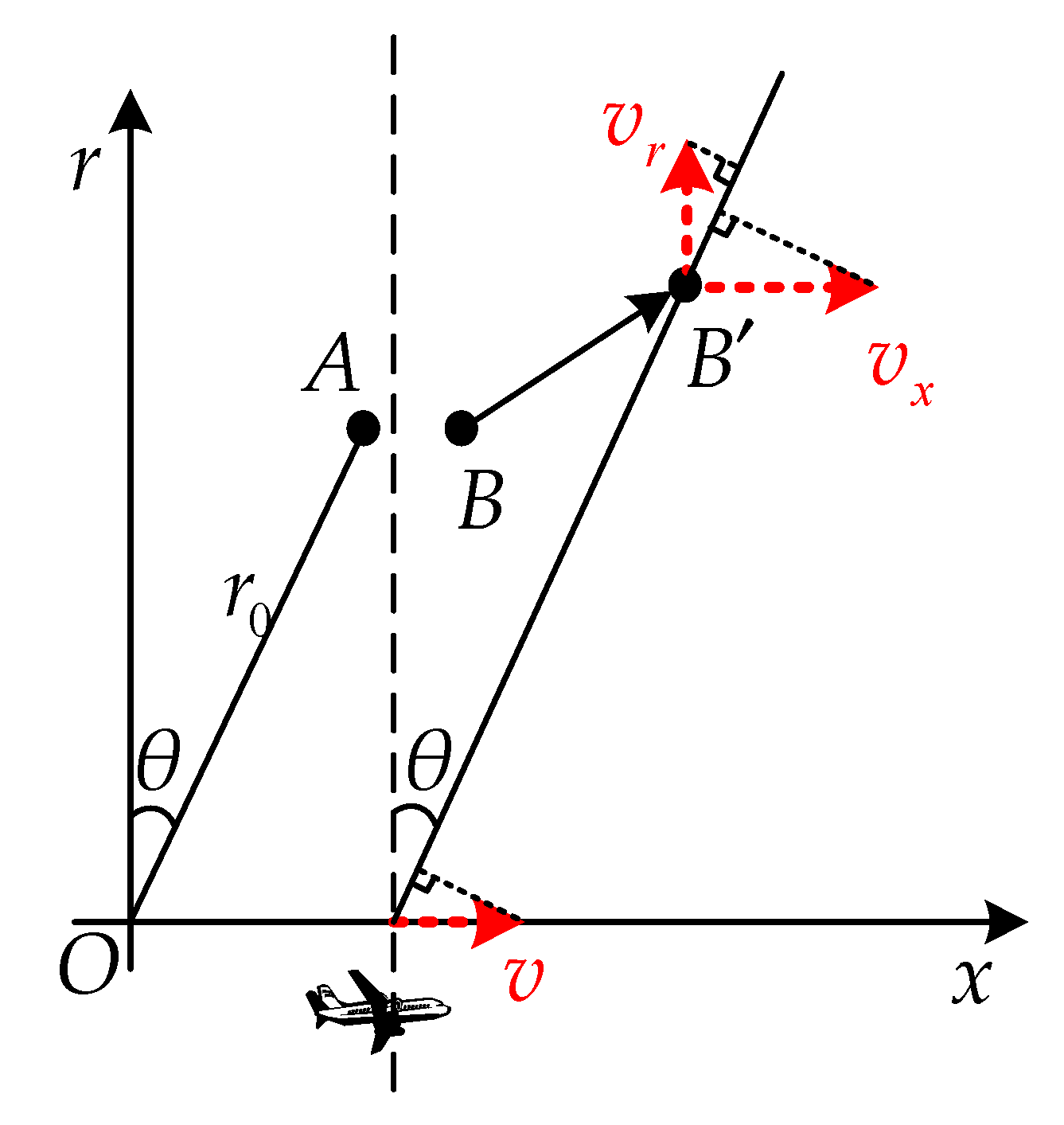
2. Signal Model
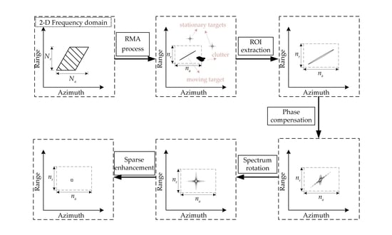
3. Proposed Method for Highly Squint SAR GMTIm
3.1. MMEA for Parameter Estimation
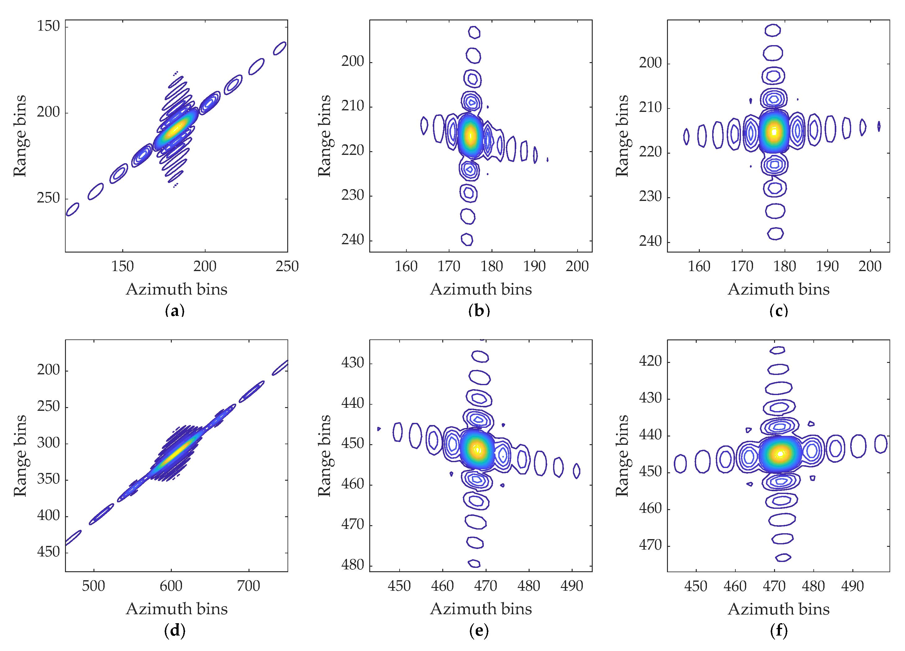
3.2. Spectrum Rotation for Geometry Correction
3.3. Sparsity Enhancement for Sidelobe Suppression
4. Results
4.1. GMTIm Based on Simulated Data
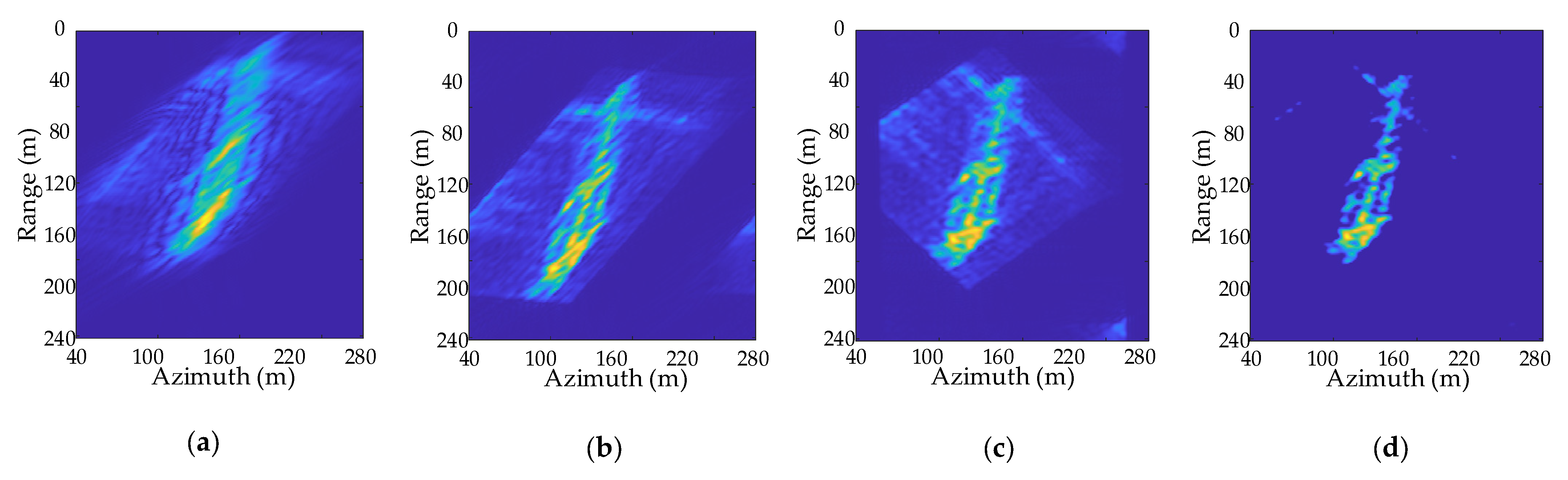
4.2. GMTIm Based on GF-3 Data
5. Conclusions
Author Contributions
Funding
Acknowledgments
Conflicts of Interest
Appendix A
References
- Werness, S.A.S.; Carrara, W.G.; Joyce, L.S.; Franczak, D.B. Moving Target Imaging Algorithm for SAR Data. IEEE Trans. Aerosp. Electron. Syst. 1990, 26, 57–67. [Google Scholar] [CrossRef]
- Çetin, M.; Stojanovi´c, I.; Önhon, Ö.; Varshney, K.; Samadi, S.; Karl, W.C.; Willsky, A.S. Sparsity-Driven Synthetic Aperture Radar Imaging: Reconstruction, Autofocusing, Moving targets, and Compressed Sensing. IEEE Signal. Process. Mag. 2014, 31, 27–40. [Google Scholar] [CrossRef]
- Graziano, M.D.; D’Errico, M.; Rufino, G. Wake Component Detection in X-band SAR Images for Ship Heading and Velocity Estimation. Remote Sens. 2016, 8, 498. [Google Scholar] [CrossRef] [Green Version]
- Zhao, Y.; Han, S.; Yang, J.; Zhang, L.; Xu, H.; Wang, J. A Novel Approach of Slope Detection Combined with Lv’s Distribution for Airborne SAR Imagery of Fast Moving Targets. Remote Sens. 2018, 10, 764. [Google Scholar] [CrossRef] [Green Version]
- Song, C.; Wang, B.; Xiang, M.; Wang, Z.; Xu, W.; Sun, X. A Novel Post-Doppler Parametric Adaptive Matched Filter for Airborne Multichannel Radar. Remote Sens. 2020, 12, 4017. [Google Scholar] [CrossRef]
- Chen, J.; Xing, M.; Yu, H.; Liang, B.; Peng, J.; Sun, G. Motion Compensation/Autofocus in Airborne Synthetic Aperture Radar: A Review. IEEE Geosci Remote Sens. Mag. 2021, 2–23. [Google Scholar] [CrossRef]
- Perry, R.P.; DiPietro, R.C.; Fante, R. SAR Imaging of Moving Targets. IEEE Trans. Aerosp. Electron. Syst. 1999, 35, 188–200. [Google Scholar] [CrossRef]
- Kirscht, M. Detection and Imaging of Arbitrarily Moving Targets with Single-Channel SAR. IET Radar Sonar Navig. 2003, 150, 7–11. [Google Scholar] [CrossRef]
- Henke, D.; Magnard, C.; Frioud, M.; Small, D.; Meier, E.; Schaepman, M.E. Moving-Target Tracking in Single-Channel Wide-Beam SAR. IEEE Trans. Geosci. Remote Sens. 2012, 50, 4735–4747. [Google Scholar] [CrossRef] [Green Version]
- Jin, G.H.; Dong, Z.; He, F.; Yu, A.X. Background-Free Ground Moving Target Imaging for Multi-PRF Airborne SAR. IEEE Trans. Geosci. Remote Sens. 2019, 57, 1949–1962. [Google Scholar] [CrossRef]
- Gu, F.F.; Zhang, Q.; Chen, Y.C. Parametric Sparse Representation Method for Motion Parameter Estimation of Ground Moving Target. IEEE Sens. J. 2016, 16, 7646–7652. [Google Scholar] [CrossRef]
- Pascazio, V.; Schirinzi, G.; Farina, A. Moving Target Detection by Alongtrack Interferometry. In Proceedings of the IEEE IGARSS, Sydney, NSW, Australia, 9–13 July 2001; pp. 3024–3026. [Google Scholar] [CrossRef]
- Suwa, K.; Yamamoto, K.; Tsuchida, M.; Nakamura, S.; Wakayama, T.; Hara, T. Image-Based Target Detection and Radial Velocity Estimation Methods for Multichannel SAR-GMTI. IEEE Trans. Geosci. Remote Sens. 2017, 55, 1325–1338. [Google Scholar] [CrossRef]
- Chen, Y.; Li, G.; Zhang, Q.; Sun, J. Refocusing of Moving Targets in SAR Images via Parametric Sparse Representation. Remote Sens. 2017, 9, 795. [Google Scholar] [CrossRef] [Green Version]
- Martorella, M.; Giusti, E.; Berizzi, F.; Bacci, A.; Mese, E.D. ISAR based technique for refocusing non-cooperative targets in SAR images. IET Radar Sonar Navig. 2012, 6, 332–340. [Google Scholar] [CrossRef]
- Zhang, Y.; Sun, J.; Lei, P.; Li, G.; Hong, W. High-Resolution SAR-Based Ground Moving Target Imaging with Defocused ROI Data. IEEE Trans. Geosci. Remote Sens. 2016, 54, 1062–1073. [Google Scholar] [CrossRef]
- Zhou, F.; Wu, R.; Xing, M.; Bao, Z. Approach for Single Channel SAR Ground Moving Target Imaging and Motion Parameter Estimation. IET Radar Sonar Navig. 2007, 1, 59–66. [Google Scholar] [CrossRef]
- Li, G.; Xia, X.G.; Peng, Y.N. Doppler Keystone Transform-An Approach Suitable for Parallel Implementation of SAR Moving Target Imaging. IEEE Geosci. Remote Sens. Lett. 2008, 5, 573–577. [Google Scholar] [CrossRef]
- Jin, G.H.; Dong, Z.; He, F.; Yu, A.X. SAR Ground Moving Target Imaging Based on a New Range Model Using a Modified Keystone Transform. IEEE Trans. Geosci. Remote Sens. 2019, 57, 3283–3295. [Google Scholar] [CrossRef]
- Wan, J.; Tan, X.; Chen, Z.; Li, D.; Liu, Q.; Zhou, Y.; Zhang, L. Refocusing of Ground Moving Targets with Doppler Ambiguity Using Keystone Transform and Modified Second-Order Keystone Transform for Synthetic Aperture Radar. Remote Sens. 2021, 13, 177. [Google Scholar] [CrossRef]
- Djurovic, I.; Thayaparan, T.; Stankovic, L. SAR Imaging of Moving Targets Using Polynomial Fourier Transform. IET Signal Process. 2008, 2, 237–246. [Google Scholar] [CrossRef] [Green Version]
- Chen, X.L.; Guan, J.; Chen, W.S.; Zhang, L.; Yu, X.H. Sparse Long-Time Coherent Integration-Based Detection Method for Radar Low-Observable Maneuvering Target. IET Radar Sonar Navig. 2020, 14, 538–546. [Google Scholar] [CrossRef]
- Huang, P.H.; Xia, X.G.; Gao, Y.S.; Liu, X.Z.; Liao, G.S.; Jiang, X. Ground Moving Target Refocusing in SAR Imagery Based on RFRT-FrFT. IEEE Trans. Geosci. Remote Sens. 2019, 57, 5476–5492. [Google Scholar] [CrossRef]
- Matan, L.; George, P.; Chrysoula, T. Low Rank Plus Sparse Decomposition of Synthetic Aperture Radar Data for Target Imaging. IEEE Trans. Comput. Imaging. 2020, 6, 491–502. [Google Scholar] [CrossRef]
- Kang, M.S.; Kim, K.T. Ground Moving Target Imaging Based on Compressive Sensing Framework with Single-Channel SAR. IEEE Sens. J. 2020, 20, 1238–1250. [Google Scholar] [CrossRef]
- Chen, Y.C.; Li, G.; Zhang, Q. Iterative Minimum Entropy Algorithm for Refocusing of Moving Targets in SAR Images. IET Radar Sonar Navig. 2019, 13, 1279–1286. [Google Scholar] [CrossRef]
- Li, Z.Y.; Liang, Y.; Xing, M.D.; Huai, Y.Y.; Gao, Y.X.; Zeng, L.T.; Bao, Z. An Improved Range Model and Omega-K-Based Imaging Algorithm for High-Squint SAR With Curved Trajectory and Constant Acceleration. IEEE Geosci. Remote Sens. Lett. 2016, 13, 656–660. [Google Scholar] [CrossRef]
- Yang, L.; Zhao, L.F.; Zhou, S. Sparsity-Driven SAR Imaging for Highly Maneuvering Ground Target by the Combination of Time-Frequency Analysis and Parametric Bayesian Learning. IEEE J. Sel. Topics Appl. Earth Observ. Remote Sens. 2017, 10, 1443–1455. [Google Scholar] [CrossRef]
- Xin, Z.H.; Liao, G.S.; Yang, Z.W.; Huang, P.H.; Ma, J.T. A fast ground moving target focusing method based on first-order discrete polynomial-phase transform. Digit. Signal Process. 2017, 60, 287–295. [Google Scholar] [CrossRef]
- Tian, M.; Liao, G.; Zhu, S.; He, X.; Liu, Y.; Li, Y. An Efficient Method for Ground Maneuvering Target Refocusing and Motion Parameter Estimation Based on DPT–KT–MFP. Remote Sens. 2021, 13, 1092. [Google Scholar] [CrossRef]
- Cumming, I.G.; Wong, F.H. Digital Processing of Synthetic Aperture Radar Data: Algorithm and Implementation; Artech House: Norwood, MA, USA, 2005. [Google Scholar]
- Yang, J.; Liu, C.; Wang, Y. Imaging and parameter estimation of fast-moving targets with single-antenna SAR. IEEE Geosci. Remote Sens. Lett. 2014, 11, 529–533. [Google Scholar] [CrossRef]
- Jing, K.; Xu, J.; Hang, Z.; Yao, D.; Long, T. GMTI for Squint Looking XTI-SAR with Rotatable Forward-Looking Array. Sensors 2016, 16, 873. [Google Scholar] [CrossRef] [PubMed] [Green Version]
- Wang, Y.; Cao, Y.H.; Qi, C.; Han, J.S.; Liu, Y.T. Multi-channel SAR-GMTI Clutter Suppression Method Based on Hypersonic Platform Forward Squint. J. Electron. Inf. Technol. 2020, 42, 458–464. [Google Scholar]
- Xiong, B.; Xu, J.; Peng, S.; Yang, J. Ground moving targets signal modeling for multi-channel squint-looking SAR. In Proceedings of the International Radar Conference, Xi’an, China, 14–16 April 2013; pp. 1–7. [Google Scholar]
- Han, J.; Cao, Y.; Yeo, T.-S.; Wang, F. Robust Clutter Suppression and Ground Moving Target Imaging Method for a Multi-channel SAR with High-Squint Angle Mounted on Hypersonic Vehicle. Remote Sens. 2021, 13, 2051. [Google Scholar] [CrossRef]
- Garren, D.A. Signature morphology effects of squint angle for arbitrarily moving surface targets in spotlight synthetic aperture radar. IEEE Trans. Geosci. Remote Sens. 2015, 53, 6241–6251. [Google Scholar] [CrossRef]
- Chen, Z.; Zhou, Y.; Zhang, L.; Lin, C.; Huang, Y.; Tang, S. Ground Moving Target Imaging and Analysis for Near-Space Hypersonic Vehicle-Borne Synthetic Aperture Radar System with Squint Angle. Remote Sens. 2018, 10, 1966. [Google Scholar] [CrossRef] [Green Version]
- Bi, H.; Bi, G.A.; Zhang, B.C.; Hong, W.; Wu, Y.R. From Theory to Application: Real-Time Sparse SAR Imaging. IEEE Trans. Geosci. Remote Sens. 2020, 58, 2928–2936. [Google Scholar] [CrossRef]
- He, X.P.; Liao, G.S.; Zhu, S.Q.; Xu, J.W.; Guo, Y.F.; Wei, J.Q. Fast Non-Searching Method for Ground Moving Target Refocusing and Motion Parameters Estimation. Digit. Signal Process. 2018, 79, 152–163. [Google Scholar] [CrossRef]


| PSNR(dB) | ISLR(dB) | ||
|---|---|---|---|
| Ideal value | −13.25 | −9.80 | 1.5708 |
| MMEA | −13.01 | −9.56 | 0.9303 |
| MMEA + SASR | −13.09 | −9.64 | 1.4366 |
| MMEA + ESASR | −13.12 | −9.71 | 1.5307 |
| 60 Degrees | 75 Degrees | |
|---|---|---|
| Ideal value | 1.5708 | 1.5708 |
| MMEA | 0.9132 | 0.8714 |
| MMEA + SASR | 1.3652 | 1.3827 |
| MMEA + ESASR | 1.5263 | 1.5174 |
Publisher’s Note: MDPI stays neutral with regard to jurisdictional claims in published maps and institutional affiliations. |
© 2021 by the authors. Licensee MDPI, Basel, Switzerland. This article is an open access article distributed under the terms and conditions of the Creative Commons Attribution (CC BY) license (https://creativecommons.org/licenses/by/4.0/).
Share and Cite
Xiong, S.; Ni, J.; Zhang, Q.; Luo, Y.; Yu, L. Ground Moving Target Imaging for Highly Squint SAR by Modified Minimum Entropy Algorithm and Spectrum Rotation. Remote Sens. 2021, 13, 4373. https://doi.org/10.3390/rs13214373
Xiong S, Ni J, Zhang Q, Luo Y, Yu L. Ground Moving Target Imaging for Highly Squint SAR by Modified Minimum Entropy Algorithm and Spectrum Rotation. Remote Sensing. 2021; 13(21):4373. https://doi.org/10.3390/rs13214373
Chicago/Turabian StyleXiong, Shichao, Jiacheng Ni, Qun Zhang, Ying Luo, and Longqiang Yu. 2021. "Ground Moving Target Imaging for Highly Squint SAR by Modified Minimum Entropy Algorithm and Spectrum Rotation" Remote Sensing 13, no. 21: 4373. https://doi.org/10.3390/rs13214373