Building Shadow Detection on Ghost Images

1
GuangXi Key Laboratory of Spatial Information and Geomatics, Guilin University of Technology, Guilin 541004, China
2
College of Geomatics and Geoinformation, Guilin University of Technology, Guilin 541004, China
*
Author to whom correspondence should be addressed.
Remote Sens. 2020, 12(4), 679; https://doi.org/10.3390/rs12040679
Submission received: 16 January 2020
/
Revised: 13 February 2020
/
Accepted: 18 February 2020
/
Published: 19 February 2020
(This article belongs to the Section Urban Remote Sensing)
Abstract
:Although many efforts have been made on building shadow detection from aerial images, little research on simultaneous shadows detection on both building roofs and grounds has been presented. Hence, this paper proposes a new method for simultaneous shadow detection on ghost image. In the proposed method, a corner point on shadow boundary is selected and its 3D approximate coordinate is calculated through photogrammetric collinear equation on the basis of assumption of average elevation within the aerial image. The 3D coordinates of the shadow corner point on shadow boundary is used to calculate the solar zenith angle and the solar altitude angle. The shadow areas on the ground, at the moment of aerial photograph shooting are determined by the solar zenith angle and the solar altitude angle with the prior information of the digital building model (DBM). Using the relationship between the shadows of each building and the height difference of buildings, whether there exists a shadow on the building roof is determined, and the shadow area on the building roof on the ghost image is detected on the basis of the DBM. High-resolution aerial images located in the City of Denver, Colorado, USA are used to verify the proposed method. The experimental results demonstrate that the shadows of the 120 buildings in the study area are completely detected, and the success rate is 15% higher than the traditional shadow detection method based on shadow features. Especially, when the shadows occur on the ground and on the buildings roofs, the successful rate of shadow detection can be improved by 9.42% and 33.33% respectively.

1. Introduction
The high resolution urban aerial images are widely used in the applications of digital city building. The original high resolution aerial images need to be orthorectificated for further applications, such as for superimposing the geographic information system (GIS) vector data [1,2]. If high-quality orthoimages are required, the building’s shadows have to be detected and compensated, since the shadows seriously affect the usability of the orthoimages [3,4,5]. In recent decades, many methods on the shadow detection are proposed and can be categorized as:
(1) Shadow detection based on the natural characteristics of shadow: According to the differences of the spectral, texture and edge information between the shadow region and the non-shadow region, the detection methods are carried out by combining the feature threshold, statistical mixed model and D-S evidence theory. For example, Turker et al. [6] proposed a method to detect the shadows by immersive watershed segmentation. The boundaries of buildings are stored as vector polygons in the geographic information system (GIS), and the shadow edges are used to match their corresponding shadows. Zhou et al. [7] compared and analyzed three methods of shadow detection. They found that the first method combined the space feature information and the space classification information of the shadow; the second method used a correction method of the linear correlation to detect the shadows; the third method proposed a data classification method of the multi-source image to determine the shadows. The experimental results demonstrated that the second method achieves a better performance on shadow detection. Liu et al. [8] proposed an object-oriented classification method which is based on the relationship between the shadow and the adjacent non-shadow areas. They found that the method can effectively detect the shadow areas in the image. Chen et al. [9] proposed an algorithm of super-pixel segmentation, which is called SLIC (Simple Linear Iterative Cluster). In this algorithm, a LDA (Linear Discriminant Analysis) is used to extract the color features of the block for shadow detection. The experimental results presented that the algorithm has better robustness and accuracy than other models. Nandini et al. [10] used a shadow detection algorithm which is based on PSO (Particle Swarm Optimization) to identify shadows. The image is first preprocessed using a bilateral filter to eliminate the noise followed by PSO-based shadow segmentation used to segment the shadow regions. The accuracy is validated using precision and recall parameters. Ye et al. [11] used the spectrum ratio and Otsu threshold segmentation methods to detect building shadows in the true color and color infrared urban aerial images. The experiments show that the result of this method is better than that of the contrast stretching method in the shadow area based on the segmentation of shadowed and unshadowed areas. Luo et al. [12] proposed a target-based shadow detection method to generate original targets by a multi-scale segmentation method-FNEA. It was observed that after the segmentation parameters are optimized, the optimal overall accuracy (OA) of the shadow detection can be improved to 89.60%. Mo et al. [13] proposed an object-oriented automatic shadow detection method, which detects shadows by pixels. A Gaussian mixture model and linear filtering are used to simulate gray distribution and to refine the soft shadow map, respectively. After combining the image segmentation, a precise shadow region with a complete shape, and without holes is obtained. Because the prior information, such as scenes, light source, etc., are not required, these types of methods are widely used for shadow detection. However, these methods still have several deficiencies, such as (1) the color features have a poor resolving power; (2) the pixel values of the texture features are need to be computed around the detection area; (3) the optimal threshold is difficult to be determined or selected, since some of the parameters are variable in different scenic areas; (4) the edge detection method is based on the edge of features, but the true shadow edges are difficult to be distinguished from other edges. Moreover, when the shadow edge widths are greater than one pixel, the shadow location is poorly determined. Therefore, the efficiency of the above methods is greatly impacted with various practical scenes.
(2) Shadow detection based on shadow descriptions using mathematical models: In this method, a statistical model of shadow detection is established, which is based on the geometry of the scene, the solar zenith angle, digital surface model (DSM), the sensor, etc. The shadow area is determined pixel by pixel. For example, Li et al. [14] proposed a method of height field ray tracing which is based on boundary of the building. The building shadow is simulated by DSM, the solar altitude and the model of the camera. The collinearity equation is used to calculate the corresponding scanning lines of the shadow. This method greatly improves the tracking efficiency. Zhou et al. [15] detected the building shadows by using a model which is stored in a DBM database. They found that the length of the shadow is determined by height of the building and the solar zenith angle, the direction of the shadow is determined by the position of the sun relative to the building, and the solar zenith angle at the time of imaging remains constant. The shadow of the building is detected by the relationship between the length and direction of the architectural shadow and the DBM. Tian et al. [16] proposed a new method that focuses on extracting shadows from a single outdoor image. A three-color attenuation model (TAM) which is based on the theory of image formation to describe the attenuation relationship between shadow and its non-shadow background is proposed. The parameters of the TAM are fixed by using the spectral power distribution (SPD) of daylight and skylight, which is estimated according to Planck radiation law. Based on TAM, a multi-step algorithm of shadow detection is proposed to extract the shadow. The algorithm obtains a single image in a real complex scene which can be applied to image processing without prior knowledge. Huang et al. [17] used Morphological Building Index (MBI) and Morphological Shadow Index (MSI) to detect shadows of buildings in dense city and town areas. Elbakary et al. [18] proposed a new model of the contours for segmenting the shadow and the dark regions, and the optimal threshold is used to distinguished real shadows and clutter complexity. Tong et al. [19] analyzed the geometric relationship between the urban buildings and their shadows in the detection of earthquake collapsed buildings. Li et al. [20] proposed the bright channel prior (BCP) to model and extract the occlusion map in an image. Then, combining the model-based result with observation cues (i.e., pixel values, luminance, and chromaticity properties) to refine the shadow mask. This method only achieves approximately an 85% success rate of shadow detection.
Obviously, the model-based shadow detection method has higher accuracy than the method of shadow detection based on the natural characteristics of shadow. The model-based shadow detection methods can accurately extract the mathematical relationship between buildings and shadows, and they are relatively simple to use therefore, they have been widely used for shadow detection especially in high resolution images. However, the following deficiencies still exist: (1) ray tracing is easily affected by three factors on the light path: absorption, reflection, and refraction; (2) joint model may confuse shadows with water regions; (3) prior information such as the location of the light source is unknown in most cases; (3) shadow detection based on aerial images does not take into account the impact of projection errors and tilt errors in the detection results. Moreover, most methods are only suitable for the shadow detection of a simple building. For the detection of the shadow area of a complex building, there is still no effective method present. For example, to completely detect the shadow area located on the building roof or complex building, an improved shadow detection model is required.
Therefore, to solve the above problems, this paper proposes a building shadow detection method on a ghost image. Orthoimage is basically an orthorectified or geometrically corrected aerial image having a uniform scale and can be used as a map. However, ghost image refers to the phenomenon where the same building roof appears twice in the orthoimage because the roof of the building is superimposed on the bottom of the building [15], and the ghost image does not consider the effect of shadows. Therefore, our method is effective in detecting the complete shadows of even complex buildings, and the shadow areas located on the building roofs. Detecting and rectifying the shadow areas in the orthoimages will improve the overall quality and accuracy of the orthoimages, and hence will improve the utilization of the orthoimages. Shadow detection and its further removal is useful for various image processing applications such as object recognition, scene interpretation, land use classification, and video surveillance. The improved images offer better accuracy and quality for real world applications such as urban planning, hydrological modeling, environmental planning, natural resources management, etc.
2. Materials and Methods
2.1. Data Set
The detailed descripts of the experimental data used in this paper can be seen in Zhou et al. [21]. In summer, it includes:
Aerial image data: the aerial image was taken by the RC30 aerial camera at an altitude of 1650 m averagely for the city of Denver, Colorado, the United States of America. Two strips with an overlap of 65% along the strip and a side overlap of 30% were set up. One aerial image with ID: dv 1119 was selected for experiments (see Figure 1). It is estimated that the ground sample distance (GSD) is averagely approximately 25.4 cm.
The ghost image was generated by the photogrammetric orthorectification algorithm on the basis of the collinear equation, i.e., which can be referred to Zhou et al. [1].
DBM data: the digital building model (DBM) describes the building structure, three-dimensional (3D) coordinates, topologic relationship, etc., and covers the entire city of Denver, downtown. The DBM was also provided by the City of Denver, Colorado. The DBM is visualized and is shown in Figure 2.
It is to be noted that the whole image had many buildings, but DBM was available only for 120 building as illustrated in Figure 2. It is one of the limitations of our work as the DBM data was only available for these 120 buildings. Complete detection meant the shadows of all the types of 120 buildings were detected, whether they were the shadows of buildings on ground or roof. We have evaluated the results both by pixels and objectsin Section 3.2.2, as required.
2.2. The Shadow’s Relationship between the Original Aerial Image and the Ghost Image
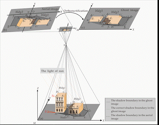
Figure 3 depicts a relationship between the aerial image and the ghost image. Figure 3a shows that the buildings are illuminated by the parallel light of the sun at a certain moment, forming shadow areas corresponding to the time on the ground and adjacent building. The points of m, O, and S are defined as the origins of the frame coordinate system-xyz, the principal point of photograph, and the center for photography, respectively. The ground nadir point is marked as Nadir.
Two buildings in Figure 1a are defined as Bldg1 and Bldg2. Bldg1 is represented with eight points A1′, B1′, C1′, D1′, A1, B1, C1, D1 and the shadow on the ground is enclosed at A1B1C1L1 A2′A2G1F1E1. The shadow area on the building roof is enclosed by L1I1H1A2′ and the shadow area on the building wall is marked as A2′H1G1A2. In the aerial image, the shadow areas of bldg1 on the ground, on the building’s roof, and on the building’s wall are a1b1c1l1a2′a2g1f1e1, l1i1h1a2′, and a2′h1g1a2, respectively. Similarly, Bldg2 consists of eight corner points A2′, B2′, C2′, D2′, A2, B2, C2, D2. The shadowed area for Bldg2 on the ground is represented by A2B2C2G2F2E2. bldg2 is the image of Bldg2 in the aerial image, and the shadow area of Bldg2 on the ground is a2b2c2g2f2e2.
The ghost image is obtained from the aerial image through conventional orthorectification algorithm. In the ghost image, a1′b1′c1′d1′ of original building roof of bldg1 is orthorectified to the original bottom of building (namely, a1b1c1d1). Similarly, a2′b2′c2′d2′ of original building roof of bldg2 is orthorectified to the bottom of the building (namely, a2b2c2d2). Meanwhile, the shadow areas of the buildings also have corresponding offsets due to the influence of the correction from roofs. As shown in Figure 3, the ghost image, the three types of line represent respectively the shadow boundary of buildings in the ghost image, the shadow boundary of buildings in the aerial image, and the right shadow boundary of buildings in the ghost image. After the orthorectification is finished, the shadow area of each building within the ghost image is probably shifted to different extent from the aerial image due to the influence of orthorectification process. Obviously, the shadow areas in the ghost image are shifted from the original shadow areas. Therefore, a shadow detection method based on the ghost image is proposed.
To establish a mathematical relationship between the DBM and the ghost image, the geographic coordinate system M-XYZ is established, and the ghost image has the same coordinate system M-XY, the coordinate of Z represents the elevation information of the buildings. The corner coordinates of a building can be directly obtained from DBM.
The walls of buildings will be invisible in a true orthoimage. Therefore, the shadow areas on the wall of buildings will not be detected in the ghost image. This paper directly determines the shadow area by detecting the shadow boundary.
2.2.1. The Shadow Boundary on the Ground
The corner point on the shadow boundary, noted as, F1 in the coordinate system M-XYZ is taken as an example to determine the shadow boundary on the ground. When the shadow is projected on the ground without blocks, the corner point on the shadow boundary, F1, corresponding to the corner point of building’s roof B1′ from Bldg1 will be directly projected on the ground. The coordinates of point F1 can be determined by the solar zenith angle α, the solar altitude angle β and point B1 (XB1, YB1, ZB1). The solar zenith angle α and the solar altitude angle β can be determined from point A1′ (XA1′, YA1′, ZA1′) and point E1 (XE1, YE1, ZE1). The coordinates of A1′ and B1 can be obtained directly from the DBM. The point E1 (XE1, YE1, ZE1) can be determined according to photogrammetric collinear equation.
2.2.2. The Shadow Boundary on the Building Roof
Due to existence of different heights of buildings in adjacent buildings, the building shadows are not all projected on the ground. The two cases that exist are as follows:
- If a building is shadowed on another tall building, this building shadow can consist of two parts: the first part is on the ground and the other part is on the wall of the front tall building.
- If a building is shadowed on another low building this building shadow can consist of three parts: the first part is on the ground, the second part is on the wall of the front low building and the third part is on the roof of the front low building. The corner point on the shadow boundary, noted as, I1 in the coordinate system M-XYZ is taken as an example to determine the shadow boundary on the roof. When the building Bldg1 is shadowed on another low building Bldg2, the corner point, I1, corresponding to the corner point of building roof C1′ from Bldg1 will be directly projected on the roof of Bldg2. The coordinates of point I1 can be determined by the solar zenith angle α, the solar altitude angle β, the height of buildings and point C1 (XC1, YC1, ZC1). The coordinates of C1 can be obtained directly from the DBM.
2.3. The Mathematical Model of the Proposed Method
As shown in Figure 4, the method proposed in this paper first selects a corner point of the shadow with a relatively small error in the aerial image through analysis of tilt error and projection error, and then correcting the corner point of shadow through the correction of systematic error. Secondly, the corrected image point coordinates are combined with the mean elevation of the ground from the DBM through the collinearity equation, to determine the unique object point image coordinate on the image plane. When the 3D ground point coordinates are known, the solar zenith angle and the solar altitude angle are also known, and then the boundary coordinates of the shadow areas on the ground and the boundary coordinates of the shadow areas on the roofs can also be determined using the solar zenith angle and the solar altitude angle. Finally, the orthorectified shadow areas in the ghost image are obtained in accordance with the boundary coordinates of shadow areas as obtained through photogrammetric orthorectification.
2.3.1. Selection of a Shadow Boundary Point on Aerial Image
The solar zenith angle is computed based on the coordinates of a selected shadow boundary point. To obtain the coordinates of the selected corner point on shadow boundary with a high precision, the tilt error, the projection error of the aerial image and the displacement of the image are taken into consideration. To reduce the projection error caused by the terrain fluctuation as possible as could, the corner point on the shadow boundary is directly selected from the ground, as depicted in Figure 5.
In Figure 5, assuming that the ground is horizontal, and the corner point E1 which is on the shadow boundary is on the ground, a tilted image (a), in which a point E1 on the ground, is taken from the exposure center S, and the image (b) is assumed an ideal horizontal image. A ray from E1 is imaged at P1 on the image (a), and P2 on the image (b). The angle θ is a tilt angle of the image (a), point O and point O2 are the principal point and the image nadir point of image (a), point Ocenter is the geometric center of image (a), point C is the isocenter of image (a), and f is the focal length of the camera. As shown in Figure 5, the line (isometric parallel) where the intersection of the image (a) and image (b) is taken as XC-axis, and the principal line on the image (a) is taken as YC-axis for establishment of the image coordinate system C-XCYC. δ represents the angle between the line CP1 and the XC-axis, the length of line CP1 is defined as rCP1, and the length of CP2 is defined as rCP2.
The displacement of image Pch caused by the tilt of the image can be expressed as:
The formulation of Equation (1) can be expressed as:
where the pixel shift Pch is related to the rCP1, θ, f and the δ, θ ∈ [0,π].
The XC-axis is on the horizontal image, and therefore the point on the XC-axis does not cause the displacement of the image. The closer to the XC-axis and the smaller the rCP1, the smaller displacement of image is achieved from shadow boundary point. Therefore, the corner point on the shadow boundary P1 (xp1, yp1) with relatively small error is manually determined in the aerial image. Since the corner point on the shadow boundary E1 is on the ground, the value of Z in E1 (XE1, YE1, Z) can be obtained from the ground mean elevation in the DBM. Finally, the corrected coordinates of P1 (xp1, yp1) by the distortion of the lens are combined with the interior and exterior orientation parameters according to the collinear Equation (3), and point E1 is determined uniquely in the DBM.
where the f is the focal length of a camera; XS, YS and ZS are the element of exterior orientation of the image; ai, bi, ci (i = 1, 2, 3) are the 9 direction cosines composed of 3 exterior orientation elements of the image.
2.3.2. Determination of the Solar Zenith Angle and the Solar Altitude Angle
The principle of linear propagation of light determines the geometric similarity between the shadow boundary and the building. As shown in Figure 1a, the side of A1E1 from the shadow boundary of Bldg1 is determined by A1A1′. If the relationship between the building and the ground is an idealized vertical state, the shadow boundary corresponding to the building wall and the roof of the building is constructed as RtΔA1′A1E1. In RtΔA1′A1E1, the α is the solar zenith angle to be obtained, and ΔX, ΔY represent the difference between the horizontal and vertical coordinates of point A1 and point E1. According to the geometric principle of the triangle, the length of the shadow is Lshadow and the solar zenith angle α can be expressed as:
where HBldg1 is the height of Bldg1.
The β can also be used to simulate the basic geometric relationship between the instantaneous sunlight and the building by DBM. In Figure 1a, the size of ΔX, ΔY can be determined by:
The solar altitude angle β is finally determined by:
2.3.3. Shadow Detection
Based on the image information, the specific position of the geometric shadow boundary is determined by α and β. The shadow boundary can consist of two parts: the shadow boundary on the ground and the shadow boundary on the roof.
The Shadow Boundary Detection on the Ground
The length of the building’s shadow can be computed by:
where the (i) is the number of buildings, HBldg(i) is the height of Bldg(i). Then the geographic coordinates (XF1, YF1) of the corner point on the shadow boundary F1 can be expressed as:
where ΔXB, ΔYB represent the difference between the horizontal and vertical coordinates of point F1 and point B1, ΔXB = Lshadow × cos(β), ΔYB= Lshadow × sin(β). The points A1 and B1 are on the same building, and the shadow corner points on the shadow boundary are projected on the same height, so that ΔXB and ΔX, ΔYB and ΔY are the same, and ΔXB can be replaced by ΔX, ΔYB can be replaced by ΔY, the same effect can be achieved. Finally, using Equation (9), all the corner points on the shadow boundary can be obtained, and the shadow boundary projected by each building on the ground can be determined by connecting the corner points sequentially.
The Shadow Boundary Detection on the Roof
The detection of the shadow boundary from the roof is relatively complex compared to the detection of the shadow boundary from the ground. Although the ghost image is a two-dimensional plane, when the shadow areas on the roofs of the buildings are detected, we have to consider different heights of the roofs from the perspective of 3D in order to obtain the intersections of the shadow projection on the roof plane. At the same time, only a few roofs actually have intersections within the scope of the shadow areas. Therefore, in order to avoid unnecessarily calculations of the projection intersections on all target projection roofs, we identify adjacent buildings that may appear in the ground shadow areas from the 2D plane and combine the height information of the buildings to determine the roofs with projected intersections in three-dimensional space (see Figure 6).
As shown in Figure 6, this paper determines the shadow boundary L1I1H1A2′ of the Bldg1 by introducing vectors in the three-dimensional space of DBM.
In Figure 6, the corner points of a shadow boundary T1, E1, F1 and G1 on the ground can be determined by the Equation (11). The vector of shadow edge is the boundary of the shadow boundary from the corner of roof A1, which is projected by the sun. The angle between the vector and the vector can be expressed as:
Point A1 and the corner points of building as the starting point and the destination of the vector , to find the vector which is between the edge and the edge . The vector needs to satisfy the following condition. The set is computed by:
According to the determination principle of angle , the , and can be computed. Since the angle is ∈∠C1D1A1, is not considered.
According to the determination principle of angle , the set of and can be computed.
Finally, the set of vector is computed by:
In the set , finding and recording the corner points of roof whose frequency (number of times) of occurrence from the same termination. When the corner points of roof which are from the same termination point cannot be found in the set , and the number of vectors those are come from different starting points in is ≥ 2, we can directly obtain intersections by changing the target projection plane compared to the ground problem. When the corner point of roof whose frequency of occurrence from the same termination point is ≥ 2 in the set , and combining the corner point of roof corresponding to the corner point of the building that meets the condition with the relative height of the building, and then the corner point of roof can be determined whether it is a projected shadow.
Obviously, only the corner point of roof A2 whose frequency (number of times) of occurrence from the same termination point is ≥ 2 in the set . Therefore, in Figure 4, the corner point of roof A2′ corresponding to the corner point of roof A2 is combined with the relative height of the buildings to determine whether the A2′ of Bldg2 is projected by the Bldg1.
The distance from point A2′ to the plane B1C1C1′B1′ need to be determined. The formulation of the plane B1C1C1′B1′ is described as:
where the coefficients , , and can be determined according to the vector of each corner point from the Bldg1. is a normal vector, which is perpendicular to the plane B1C1C1′B1′. The vector can be represented by the coordinates of point and :
The distance from point to the plane B1C1C1′B1′ can be expressed as:
where
When the angle between and satisfies the condition of Equation (18), the corner point of roof can be judged that the corner point is projected shadow by Bldg1.
where .
In Figure 6, only the corner point of roof is projected shadow by Bldg1, the shadow boundary of roof can be determined as follows.
According to the method of point F1 from Equation (9), point I1 is computed, and the roof of Bldg2 is used as the projection plane of the Bldg1. The lengths of the shadow formed by the four corner points of roof on the same height, from the same building and projected on different levels of plane are different. Therefore, the length of the shadow which is the corner point of roof projection on the roof of the Bldg2 is recorded as Lshadow1:
The coordinates of I1 can be expressed as:
where
where XI1 and YI1 represent the horizontal and vertical difference between point A2 and point I1. Determination of point L1 and H1 which are located on the boundary of roof is based on the same method mentioned above (method presented in this section), to determine the corner point on the shadow boundary C1’ from Bldg1’s roof point projected on the roof of Bldg2, and then the intersection points L1, H1 can be determined. The shadow boundary L1 I1H1 A2′ of the Bldg1 projected on the roof of the Bldg2 can be determined.
3. Results and Discussion
3.1. Results
3.1.1. Determination the Solar Zenith Angle and the Solar Altitude Angle
In this paper, the aerial image is equivalent to image (a) in Figure 5. The principal point O, the image nadir point O2, the isocenter C [22] (pp.217–218), the corner point on the shadow boundary E1, and the isometric parallel are determined on the aerial image. Since the discussion of Section 3.1.1 requires referring the position of O and E1 in the aerial image, the results of the selected points O, O2, C, E1 and the isometric parallel are directly displayed on the aerial image, as shown in Figure 7. Then the solar zenith angle and the solar altitude angle are computed as α = 49.812° and β = 57.500°, using Equations (4)–(7).
In order to explain the advantages of selecting the shadow corner point EI and to verify the accuracy of the angle α and the angle β, we selected and analyzed the result of the point selection by comparing the other five shadow boundary corner points in the experimental area (see Figure 8). In Figure 8, The BLD is a building which is close to the principal point O. Point 1 is a corner point of shadow corresponding to BLD. Numbers 1–4 are the other four corner points of shadow which are arbitrarily selected in the experimental area.
We obtained the angle α and the angle β corresponding to the corner points of shadow (numbers 2–5) respectively, and calculated the height of the building BLD according to the calculation results and the corner point of shadow 1, respectively. The experimental results are shown in Table 1:
Based on the principle that the displacement of image is smaller as this point approaches the principal point [22] (p. 134), the building BLD closest to the principal point is regarded as a building closest to the true coordinate information. The magnitude of the difference between the calculated height of the BLG and the actual height of the BLG can be used to determine the size of the error of the corresponding corner point of shadow. According to Table 1, we found that the height of the BLD calculated by point E1 is closest to the actual height of the BLD; although the distance between the corner point of shadow 2 and the corner point of shadow 5 is similar to the principal point O, the size of the error is not similar, and point 5 which is closer to the isometric parallel and the distance from the isocenter point C, is relatively close and has a smaller error; point 4 which is far away from the isometric parallel and is the farthest from the isocenter C, has a larger error than other points. Therefore, we observed that the angle α and angle β calculated by the shadow point E1 closest to the isometric parallel and close to the isocenter C, selected in this paper are more accurate and E1 point is better than the results of other shadow points.
3.1.2. Shadow Detection
The Shadow Area on the Ground
The corner point coordinates of the shadow boundary projected on the ground in the DBM are derived from the solar zenith angle α and the solar altitude angle β according to Equations (5)–(7). As seen from Figure 9, a1, b1, c1, and d1 are the shadow areas from the four independent buildings in the DBM.
The shadow area on the ground and related data obtained in the DBM are converted into ghost images for displaying. The result shown in Figure 10 shows that the black shadow areas corresponding to different ghost roofs have different distances. The shadow areas formed by buildings of different heights have different lengths. The black areas are the completed areas of shadow where the buildings are projected onto the ground.
The Shadow Area on the Roof
The shadow areas on the ghost roof are determined by Equations (10)–(21). As seen from Figure 11, the coordinate system is the same as the coordinate system used by the ghost image. To facilitate the superimposition of the later layers, the shadow areas on the ghost roofs are highlighted in blue to make a distinction with the ground shadow.
The shadow areas on the ground from the ghost image and the shadow areas from the roofs are displayed in Figure 12. As seen from Figure 12, the complete shadow areas of four groups of buildings can be detected.
Using the operations outlined above, the shadow areas associated with all the 120 buildings in the study area are completely detected through DBM using the method proposed in this paper, and the gray values of the corresponding pixels are assigned to zero (i.e., black; see Figure 13). And then the shadow areas are all completely detected through DBM, the next step is to store boundary coordinates of the shadow areas, and orthorectifying the shadow areas according to the stored data.
For comparison tests, we have selected and used a heterogeneous patch of the area from our DBM consisting of three different types of buildings, i.e., (a) buildings having plane roofs, (b) buildings having tilts in the roofs, and buildings having some small rooms on the roofs. We used all these types of distinct buildings in our comparison tests as illustrated in Figure 14.
Figure 14b depicts a result that is generated by using our method. The red frames are only the markers to highlight or focus the areas on Figure 14a,b, just to compare and show the difference between a ghost image which is not orthorectified and the results of our method. Comparing Figure 14a,b, we observed the significant changes in the roof shadow areas marked by red frames. It is to be noted that the shadow area on the horizontal roof after the orthorectification does not overlap, and shadow area of the buildings having inclined roof has increased significantly. This is because the building shadows in Figure 14a are corrected by the traditional orthorectification method, and there are overlapping areas on the roofs, due to which some of the shadows of roofs cannot be completely displayed. Figure 14b shows the improvements in the image after using the improved orthorectification method. It is evident from Figure 14b that the shadow areas on the inclined roofs and horizontal roofs are corrected and have improved after orthorectification.
From Figure 14, the following can be concluded.
- (1)
- The shadow areas associated with all the 120 buildings in the study area are completely detected.
- (2)
- The proposed method not only detects the shadow areas on the horizontal roofs, but also detects shadow from buildings having tilts in the roofs, and buildings having some small rooms on the roofs (see a(2) and b(2)). The shadow from buildings having tilts in the roofs, and buildings having some small rooms on the roofs (see a(1), b(1), a(3) and b(3)).
- (3)
- The proposed method can simultaneously detect the shadows of buildings on the roofs and on the grounds.
3.2. Discussion
3.2.1. Accuracy Analysis
The experimental results mentioned above show that the proposed method can completely detect the shadows of buildings on the ghost images.
To test the accuracy of the experiment, the final experimental results are compared with the original shadow area from the ghost image. The results of the comparisons are displayed in Figure 15.
In Figure 15, we superimposed the shadow boundaries which are orthorectificated onto the original ghost image and statistically analyzed their accuracy by presenting four magnified buildings as examples. It can be observed that Bld-1, Bld-2, Bld-3, and Bld-4 have offsets of 1–3, 1–3, 0–3, and 3–5 pixels, respectively. Therefore, an average offset of 1.0–3 pixels was found.
3.2.2. Accuracy Comparison
Since there is no detailed model-based shadow detection method for roofs at present, we compare this method with the traditional shadow detection method based on the features of shadows [18]. The shadow areas detected by the two methods are displayed (see Figure 16):
As shown in Figure 16, the comparison can be summarized as follows:
(1) Comparison of Figure 16a with Figure 16b: Figure 16a uses the traditional shadow detection method based on features of the shadow to detect the shadow on the ground. The results show that on one hand, when using traditional methods based on shadow features to detect and segment the ground shadow area, if the range of the shadow area on the ground is detected to be small or the brightness of some shadow areas on the ground is close to the brightness of non-shadow areas, shadow areas will not be detected or cannot be fully detected; on the other hand, due to the influence of ground reflectivity and illumination conditions, traditional shadow detection methods based on shadow features are prone to false detection, missed detection and multiple detections. However, in Figure 16b, the model-based shadow detection method proposed in this paper can directly and correctly detect the shadow area on the ground without considering the effects of ground reflectivity and illumination conditions.
(2) Comparison of Figure 16c with Figure 16d: Figure 16c uses the traditional shadow detection method based on features of the shadow to detect the shadow on the roofs. The results show that because brightness of some roofs is close to the brightness of the shadow areas, the shadow areas on the roof cannot be detected correctly; the shadow area of the slanting roofs cannot be detected because its brightness is higher than other shadow areas accurately detected. While the result of the proposed method not only detects the shadow on the roof (the roof is highlighted in blue), but also detects the edge of the shadow areas completely.
(3) Comparison of Figure 16e with Figure 16f: Figure 16e uses the traditional shadow detection method based on features of the shadow to simultaneously detect the shadows of building on the roofs and on the grounds. The result shows that the proposed method can not only greatly improve the integrity of the detection results, but also can simultaneously detect the shadows of building on the roofs and on the grounds.
Comparison of the model-based shadow detection method proposed in this paper with the traditional shadow detection method based on features of the shadow: the model-based shadow detection method proposed in this paper can improve the detection rate of shadows on the ground by 9.42% and the detection rate of roof shadows by 33.33%. The statistical results are listed in Table 2.
To further analyze the performance of the proposed method, the correctness rate (Ptd = Ctd ÷ Ct × 100%), false alarm rate (Pfd = Cfd ÷ Cd × 100%), and the result of missed detection rate (Pld = Cld ÷ Ct × 100%) are used in this paper. As shown in Table 3, where Ct represents the number of shadows of the actual building; Cd represents the number of shadows actually detected; Ctd represents the number of shadows of the detected real buildings; Cfd indicates the number of unshadow areas detected as false alarms; Cld indicates the number of shadows missed. The method of this paper can not only improve the accuracy rate to 15% and reduce the false alarm rate to 6.54% but also reduce the missed detection rate to 9.17% compared to the traditional method.
From the literature review, it was observed that there is no such model-based shadow detection method currently available that is capable of detecting the shadow of the roof of a building. The main advantage of our method is the ability of the model to detect the shadow of a building roof. However, in the present study we used the traditional shadow detection method based on features of the shadow also. It was used only for comparison of our experimental results.
Although the traditional method (methods using shadow features) is capable of detecting the shadows of the features both on the ground and roofs to some extent but the accuracy and rate of the shadow detection is not very high. However, our method has a relatively higher accuracy and rate of the shadow detection, both on ground and roofs (Table 2 and Table 3).
One of the limitations of this study is that the data in this article relies on the specific DBM dataset, and DBM dataset is not currently available for other regions, therefore it is not possible to provide the detection results for other regions. Although it will be interesting to do such analysis in future. However, this paper has carried out detailed verification of the detection methods through four independent buildings, and has also shown the test results for all 120 buildings in the experimental area. At the same time, we have added a set of verification data to verify the feasibility of this method as shown in Section 3.2.1. Therefore, our model-based shadow detection method can detect the shadow areas of 120 buildings within the experimental area, including the shadow areas on the roofs of the buildings and shadows on the grounds. The quality of the DBM may affect the results of this method which is another limitation of this study.
4. Conclusions
To detect the shadows of the buildings in high-resolution urban imagery, this paper proposes a method that uses the DBM as an over-model to detect the shadows on both building roofs and grounds simultaneously. In this method, the solar zenith angle and the solar altitude angle are determined by selecting the geographical information of the corner point on the shadow boundary in the aerial image. The proposed method displays the actual shadow area which is determined in the DBM onto a ghost image.
There are obviously differences between the proposed method and the traditional shadow detection methods based on features of the shadow. On one hand, due to the influence of ground reflectivity and illumination conditions, traditional shadow detection methods based on shadow features are prone to false detection, missed detection and multiple detections, which may bring big errors to the detection results. However, the model-based shadow detection method proposed in this paper uses DBM scene, and this method is not influenced by ground reflectivity and illumination conditions. On the other hand, traditional shadow detection methods based on shadow features easily miss the detection of shadows on slating roofs with relatively high brightness, the multiple detections will also occur for some roofs with the same brightness as the shadow, but the model-based shadow detection method proposed in this paper detected the shadow areas on the roofs and ground of 120 buildings in the test area successfully, and the rate of shadow detection can be improved by 9.42% and 33.33% respectively. The overall detection accuracy of this method is also improved, which is 15% higher than traditional shadow detection method based on features of the shadow. Despite the complexity of the proposed algorithm, a high detection accuracy of roof shadows can be achieved which was not achieved in previous works. We believe this method can greatly improve the quality and accuracy of the digital orthoimages of a city, and can subsequently improve the utilization of the orthoimages.
Author Contributions
G.Z. contributed to the experimental design, advise of the idea and improvement of the manuscript; H.S. provides important support for the research, acquisition, analysis and interpretation of data, contributed the manuscript and takes responsibility for all aspects of the research. All authors have read and agreed to the published version of the manuscript.
Funding
This paper is financially supported by the National Natural Science of China under Grant numbers 41431179,41961065; Guangxi Innovative Development Grand Grant under the grant number: GuikeAA18118038, GuikeAA18242048; the National Key Research and Development Program of China under Grant numbers 2016YFB0502501 and the BaGuiScholars program of Guangxi (Guoqing Zhou).
Acknowledgments
The author would like to thank the reviewers for their constructive comments and suggestions.
Conflicts of Interest
The authors declare no conflict of interest.
References
- Zhou, G.; Xie, W.; Cheng, P. Orthoimage Creation of Extremely High Buildings. IEEE Trans. Geosci. Remote Sens. 2008, 46, 4132–4141. [Google Scholar] [CrossRef]
- Zhou, G.; Zhang, R.; Liu, N.; Huang, J.; Zhou, X. On-Board Ortho-Rectification for Images Based on an FPGA. Remote Sens. 2017, 9, 874. [Google Scholar] [CrossRef] [Green Version]
- Wang, Q.; Yan, L.; Yuan, Q.; Ma, Z. An Automatic Shadow Detection Method for VHR Remote Sensing Orthoimagery. Remote Sens. 2017, 9, 469. [Google Scholar] [CrossRef] [Green Version]
- Zhou, G.; Schickler, W.; Thorpe, A.; Song, P.; Chen, W.; Song, C. True orthoimage generation in urban areas with very tall buildings. Int. J. Remote Sens. 2004, 25, 5163–5180. [Google Scholar] [CrossRef]
- Wu, J.; Bauer, M.E. Evaluating the Effects of Shadow Detection on QuickBird Image Classification and Spectroradiometric Restoration. Remote Sens. 2013, 5, 4450–4469. [Google Scholar] [CrossRef] [Green Version]
- Türker, M.; Sümer, E. Building-based damage detection due to earthquake using the watershed segmentation of the post-event aerial images. Int. J. Remote Sens. 2008, 29, 3073–3089. [Google Scholar] [CrossRef]
- Zhou, W.; Huang, G.; Troy, A.R.; Cadenasso, M. Object-based land cover classification of shaded areas in high spatial resolution imagery of urban areas: A comparison study. Remote Sens. Environ. 2009, 113, 1769–1777. [Google Scholar] [CrossRef]
- Liu, W.; Yamazaki, F. Object-Based Shadow Extraction and Correction of High-Resolution Optical Satellite Images. IEEE J. Sel. Top. Appl. Earth Obs. Remote Sens. 2012, 5, 1296–1302. [Google Scholar] [CrossRef]
- Chen, D.; Shang, S.; Wu, C. Shadow-based Building Detection and Segmentation in High-resolution Remote Sensing Image. J. Multimed. 2014, 9, 181–188. [Google Scholar] [CrossRef]
- Nandini, D.U.; Leni, E.S. Efficient shadow detection by using PSO segmentation and region-based boundary detection technique. J. Supercomput. 2018, 75, 3522–3533. [Google Scholar] [CrossRef]
- Ye, Q.; Xie, H.; Xu, Q. Removing Shadows from High-Resolution Urban Aerial Images Based on Color Constancy. ISPRS Int. Arch. Photogramm. Remote Sens. Spat. Inf. Sci. 2012, 21, 525–530. [Google Scholar] [CrossRef] [Green Version]
- Luo, H.; Wang, L.; Shao, Z.; Li, D. Development of a multi-scale object-based shadow detection method for high spatial resolution image. Remote Sens. Lett. 2015, 6, 59–68. [Google Scholar] [CrossRef]
- Mo, N.; Zhu, R.; Yan, L.; Zhao, Z. Deshadowing of Urban Airborne Imagery Based on Object-Oriented Automatic Shadow Detection and Regional Matching Compensation. IEEE J. Sel. Top. Appl. Earth Obs. Remote Sens. 2018, 11, 585–605. [Google Scholar] [CrossRef]
- Li, Y.; Gong, P.; Sasagawa, T. Integrated shadow removal based on photogrammetry and image analysis. Int. J. Remote Sens. 2005, 26, 3911–3929. [Google Scholar] [CrossRef]
- Zhou, G.; Chen, W.; Kelmelis, J.; Zhang, D. A comprehensive study on urban true orthorectification. IEEE Trans. Geosci. Remote Sens. 2005, 43, 2138–2147. [Google Scholar] [CrossRef]
- Tian, J.; Sun, J.; Tang, Y. Tricolor Attenuation Model for Shadow Detection. IEEE Trans. Image Process. 2009, 18, 2355–2363. [Google Scholar] [CrossRef]
- Huang, X.; Zhang, L. Morphological Building/Shadow Index for Building Extraction From High-Resolution Imagery Over Urban Areas. IEEE J. Sel. Top. Appl. Earth Obs. Remote Sens. 2011, 5, 161–172. [Google Scholar] [CrossRef]
- Elbakary, M.I.; Iftekharuddin, K.M. Shadow Detection of Man-Made Buildings in High-Resolution Panchromatic Satellite Images. IEEE Trans. Geosci. Remote Sens. 2013, 52, 5374–5386. [Google Scholar] [CrossRef]
- Tong, X.; Lin, X.; Feng, T.; Xie, H.; Liu, S.; Hong, Z.; Chen, P. Use of shadows for detection of earthquake-induced collapsed buildings in high-resolution satellite imagery. ISPRS J. Photogramm. Remote Sens. 2013, 79, 53–67. [Google Scholar] [CrossRef]
- Li, J.; Hu, Q.; Ai, M. Joint Model and Observation Cues for Single-Image Shadow Detection. Remote Sens. 2016, 8, 484. [Google Scholar] [CrossRef] [Green Version]
- Zhou, G.; Wang, Y.; Yue, T.; Ye, S.; Wang, W. Building Occlusion Detection from Ghost Images. IEEE Trans. Geosci. Remote Sens. 2016, 55, 1074–1084. [Google Scholar] [CrossRef]
- Wolf, P.R.; Dewitt, B.A. Elements of Photogrammetry with Applications in GIS, 3rd ed.; McGraw-Hill: San Mateo, CA, USA, 2000; pp. 217–218. [Google Scholar]
Figure 1.
(a) is the aerial image. (b) is the ghost image.

Figure 2.
Three-dimensional display of digital building model on the ghost image.

Figure 3.
Relationship between the shadows in the aerial image and the ghost image. (a) DBM and shadow areas. (b) Image projected onto the image plane. (c) Ghost image after orthorectification.
Figure 3.
Relationship between the shadows in the aerial image and the ghost image. (a) DBM and shadow areas. (b) Image projected onto the image plane. (c) Ghost image after orthorectification.

Figure 4.
The flow chart of the shadow detection.

Figure 5.
Selection of a shadow boundary point.

Figure 6.
Roof shadow detection method.

Figure 7.
Selected shadow boundary point on the ghost image.

Figure 8.
The accuracy analysis of the solar zenith angle and the solar altitude angle.

Figure 9.
Detected shadow areas on the ground through DBM with gray values assigned to zero (i.e., black).
Figure 9.
Detected shadow areas on the ground through DBM with gray values assigned to zero (i.e., black).

Figure 10.
The shadows on the ground in the ghost images.

Figure 11.
The shadows on the ghost roofs.

Figure 12.
The results of detection from the buildings.

Figure 13.
The result of final detection through DBM.

Figure 14.
(a) is the shadow areas of ghost image that are not orthorectificated. (b) is the result of our method.
Figure 14.
(a) is the shadow areas of ghost image that are not orthorectificated. (b) is the result of our method.

Figure 15.
Accuracy comparison between the experimental results and the original ghost image.

Figure 16.
Comparative analysis between the proposed method and the traditional shadow detection method based on features of the shadow. (a) The result of the traditional shadow detection method based on features of the shadow to detect the shadow on the ground. (b) The result of our method to detect the shadow on the ground. (c) The result of the traditional shadow detection method based on features of the shadow to detect the shadow on the roofs. (d) The result of our method to detect the shadow on the roofs. (e) The result of the traditional shadow detection method based on features of the shadow to simultaneously detect the shadows of building on the roofs and on the ground. (f) The result of our method to simultaneously detect the shadows of building on the roofs and on the ground.


Table 1.
The accuracy analysis of the solar zenith angle and the solar altitude angle.
| The Corner Point of Shadow | α/° | β/° | The Height of BLD/ft | The Actual Height of BLD/ft | The Difference between the Height of BLD and the Actual Height of BLD/ft |
|---|---|---|---|---|---|
| E1 | 49.812 | 57.500 | 148.838 | 148.900 | 0.062 |
| 2 | 51.147 | 58.586 | 152.479 | 148.900 | 3.579 |
| 3 | 48.964 | 57.176 | 144.444 | 148.900 | 4.456 |
| 4 | 47.808 | 57.300 | 138.693 | 148.900 | 10.207 |
| 5 | 49.694 | 58.096 | 148.216 | 148.900 | 0.684 |
Table 2.
Comparison of the two methods.
| Approach | Number of Detected Buildings | Number of the Shadow Areas on the Ground Detected | Number of the Shadow Areas on the Roofs Detected | Improved Shadow Detection Rate on the Ground | Improved Shadow Detection Rate on the Roof |
|---|---|---|---|---|---|
| The traditional shadow detection method based on features of the shadow | 120 | 113 | 10 | - | - |
| Our method | 120 | 120 | 15 | 9.42% | 33.33% |
Table 3.
Comparison of detection accuracy by two methods.
| The Results | The Traditional Shadow Detection Method Based on Features of the Shadow (The Number of Buildings) | The Proposed Method (The Number of Buildings) |
|---|---|---|
| Ct | 120 | 120 |
| Cd | 116 | 120 |
| Ctd | 102 | 120 |
| Cfd | 7 | 0 |
| Cld | 11 | 0 |
| Ptd | 85% | 100% |
| Pfd | 6.54% | 0 |
| Pld | 9.17% | 0 |
© 2020 by the authors. Licensee MDPI, Basel, Switzerland. This article is an open access article distributed under the terms and conditions of the Creative Commons Attribution (CC BY) license (http://creativecommons.org/licenses/by/4.0/).
Share and Cite
MDPI and ACS Style
Zhou, G.; Sha, H. Building Shadow Detection on Ghost Images. Remote Sens. 2020, 12, 679. https://doi.org/10.3390/rs12040679
AMA Style
Zhou G, Sha H. Building Shadow Detection on Ghost Images. Remote Sensing. 2020; 12(4):679. https://doi.org/10.3390/rs12040679
Chicago/Turabian StyleZhou, Guoqing, and Hongjun Sha. 2020. "Building Shadow Detection on Ghost Images" Remote Sensing 12, no. 4: 679. https://doi.org/10.3390/rs12040679
Note that from the first issue of 2016, this journal uses article numbers instead of page numbers. See further details here.