Automated Resistivity Profiling (ARP) to Explore Wide Archaeological Areas: The Prehistoric Site of Mont’e Prama, Sardinia, Italy


Abstract
:
1. Introduction
2. Materials and Methods
2.1. The Archaeological Site of Mont’e Prama
2.2. Geological Setting
2.3. Methods and Instrumental Layout
2.3.1. ARP Survey
- the first dataset was collected in the sector located in the north of the area involved in the archaeological excavations (large 20,155 m2);
- the second dataset was acquired in the area around the open archaeological digs (2730 m2).
2.3.2. GPR Survey
3. Results
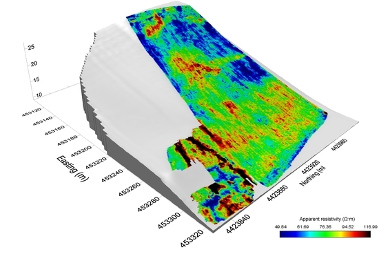
3.1. ARP Results
3.2. Vertical Analysis of ARP Anomalies and Comparison with GPR Data
4. Discussion
- dark gray color: areas with highly evident ARP anomalies without GPR comparison;
- red color: areas with high ARP resistivity contrast to background and consistent high amplitude GPR signals;
- orange color: areas with ARP anomalies with good accordance to strong GPR reflections;
- yellow color: areas with significant features of ARP anomalies with only partial accordance with GPR signals;
- light gray color: areas with relatively weak ARP spatial patterns without clear agreement or comparison with GPR data.
5. Conclusions
Author Contributions
Funding
Acknowledgments
Conflicts of Interest
References
- Campana, S. Archaeological site detection and mapping: Some thoughts on differing scales of detail and archaeological ‘non-visibility’. In Seeing the Unseen. Geophysics and Landscape Archaeology; Campana, S., Piro, S., Eds.; CRC Press, Taylor & Francis Group: London, UK, 2009; pp. 5–26. [Google Scholar]
- Drahor, M.G.; Göktürkler, G.; Berge, M.A.; Kurtulmuş, T. Özgür Application of electrical resistivity tomography technique for investigation of landslides: A case from Turkey. Environ. Earth Sci. 2006, 50, 147–155. [Google Scholar]
- Boyle, A.; Wilkinson, P.B.; Chambers, J.E.; Meldrum, P.I.; Uhlemann, S.; Adler, A. Jointly reconstructing ground motion and resistivity for ERT-based slope stability monitoring. Geophys. J. Int. 2017, 212, 1167–1182. [Google Scholar] [CrossRef]
- Perrone, A.; Lapenna, V.; Piscitelli, S. Electrical resistivity tomography technique for landslide investigation: A review. Earth-Sci. Rev. 2014, 135, 65–82. [Google Scholar] [CrossRef]
- Mastrocicco, M.; Vignoli, G.; Colombani, N.; Abu Zeid, N. Surface electrical resistivity tomography and hydrogeological characterization to constrain groundwater flow modeling in an agricultural field site near Ferrara (Italy). Environ. Earth Sci. 2009, 61, 311–322. [Google Scholar] [CrossRef]
- Watlet, A.; Kaufmann, O.; Triantafyllou, A.; Poulain, A.; Chambers, J.E.; Meldrum, P.I.; Wilkinson, P.B.; Hallet, V.; Quinif, Y.; Van Ruymbeke, M.; et al. Imaging groundwater infiltration dynamics in the karst vadose zone with long-term ERT monitoring. Hydrol. Earth Syst. Sci. 2018, 22, 1563–1592. [Google Scholar] [CrossRef] [Green Version]
- Braga, A.C.O.; Malagutti, F.W.; Dourado, J.C.; Chang, H.K. Correlation of Electrical Resistivity and Induced Polarization Data with Geotechnical Survey Standard Penetration Test Measurements. J. Environ. Eng. Geophys. 1999, 4, 123–130. [Google Scholar] [CrossRef]
- Cosenza, P.; Marmet, E.; Rejiba, F.; Cui, Y.J.; Tabbagh, A.; Charlery, Y. Correlations between geotechnical and electrical data: A case study at Garchy in France. J. Appl. Geophys. 2006, 60, 165–178. [Google Scholar] [CrossRef]
- Soupios, P.M.; Georgakopoulos, P.; Papadopoulos, N.; Saltas, V.; Andreadakis, A.; Vallianatos, F.; Sarris, A.; Makris, J.P. Use of engineering geophysics to investigate a site for a building foundation. J. Geophys. Eng. 2007, 4, 94–103. [Google Scholar] [CrossRef]
- Chambers, J.; Oglivy, R.; Meldrum, P.; Nissen, J. 3D resistivity imaging of buried oil- and tar-contaminated waste deposits. Eur. J. Environ. Eng. Geophys. 1999, 4, 3–15. [Google Scholar]
- Chambers, J.E.; Kuras, O.; Meldrum, P.I.; Ogilvy, R.D.; Hollands, J. Electrical resistivity tomography applied to geologic, hydrogeologic, and engineering investigations at a former waste-disposal site. Geophysics 2006, 71, B231–B239. [Google Scholar] [CrossRef] [Green Version]
- Corwin, D.L.; Lesch, S.M. Application of soil electrical conductivity to precision agriculture: theory, principles and guidelines. Agron. J. 2003, 95, 455–471. [Google Scholar] [CrossRef]
- Garre, S.; Javaux, M.; VanderBorght, J.; Pagès, L.; Vereecken, H. Three-Dimensional Electrical Resistivity Tomography to Monitor Root Zone Water Dynamics. Vadose Zone J. 2011, 10, 412–424. [Google Scholar] [CrossRef] [Green Version]
- Beff, L.; Günther, T.; Vandoorne, B.; Couvreur, V.; Javaux, M. Three-dimensional monitoring of soil water content in a maize field using Electrical Resistivity Tomography. Hydrol. Earth Syst. Sci. 2013, 17, 595–609. [Google Scholar] [CrossRef] [Green Version]
- Drahor, M.G. Integrated geophysical studies in the upper part of Sardis archaeological site, Turkey. J. Appl. Geophys. 2006, 59, 205–223. [Google Scholar] [CrossRef]
- Cardarelli, E.; Fischanger, F.; Piro, S. Integrated geophysical survey to detect buried structures for archaeological prospecting. A case-history at Sabine Necropolis (Rome, Italy). Near Surf Geophys. 2008, 6, 15–20. [Google Scholar] [CrossRef]
- Gaffney, C. Detecting trends in the prediction of the buried past: a review of geophysical techniques in archaeology. Archaeometry 2008, 50, 313–336. [Google Scholar] [CrossRef]
- Trogu, A.; Ranieri, G.; Calcina, S.V.; Piroddi, L. The Ancient Roman Aqueduct of Karales (Cagliari, Sardinia, Italy): Applicability of Geophysics Methods to Finding the Underground Remains. Archaeol. Prospect. 2014, 21, 157–168. [Google Scholar] [CrossRef]
- Ranieri, G.; Godio, A.; Loddo, F.; Stocco, S.; Casas, A.; Capizzi, P.; Messina, P.; Orfila, M.; Cau, M.; Chávez, M.; et al. Geophysical prospection of the Roman city of Pollentia, Alcúdia (Mallorca, Balearic Islands, Spain). J. Appl. Geophys. 2016, 134, 125–135. [Google Scholar] [CrossRef]
- Ranieri, G.; Trogu, A.; Loddo, F.; Piroddi, L.; Cogoni, M. Digital Museum from Integrated 3D Aerial Photogrammetry, Laser Scanner and Geophysics Data. In Proceedings of the 24th European Meeting of Environmental and Engineering Geophysics, Porto, Portugal, 9–13 September 2018; pp. 1–5. [Google Scholar]
- Piroddi, L.; Vignoli, G.; Trogu, A.; Deidda, G.P. Non-destructive Diagnostics of Architectonic Elements in San Giuseppe Calasanzio’s Church in Cagliari: A Test-case for Micro-geophysical Methods within the Framework of Holistic/integrated Protocols for Artefact Knowledge. In Proceedings of the 2018 IEEE International Conference on Metrology for Archaeology and Cultural Heritage, Cassino, Italy, 22–24 October 2018; pp. 17–21. [Google Scholar]
- Yilmaz, S.; Balkaya, Ç.; Çakmak, O.; Oksum, E. GPR and ERT explorations at the archaeological site of Kılıç village (Isparta, SW Turkey). J. Appl. Geophys. 2019, 170, 103859. [Google Scholar] [CrossRef]
- Samouëlian, A.; Cousin, I.; Tabbagh, A.; Bruand, A.; Richard, G. Electrical resistivity survey in soil science: A review. Soil Tillage Res. 2005, 83, 173–193. [Google Scholar] [CrossRef] [Green Version]
- Chávez, G.; Tejero, A.; Alcantara, M.A.; Chavez, R.E. The ‘L-Array’, a tool to characterize a fracture pattern in an urban zone. In Proceedings of the 17th Near Surface Geophysics meeting, European Section Meeting, Leicester, UK, 12–14 September 2011. [Google Scholar]
- Berge, M.A.; Drahor, M.G. Electrical Resistivity Tomography Investigations of MultiLayered Archaeological Settlements: Part I - Modelling. Archaeol. Prospect. 2011, 18, 159–171. [Google Scholar] [CrossRef]
- Santarato, G.; Ranieri, G.; Occhi, M.; Morelli, G.; Fischanger, F.; Gualerzi, D. Three-dimensional Electrical Resistivity Tomography to control the injection of expanding resins for the treatment and stabilization of foundation soils. Eng. Geol. 2011, 119, 18–30. [Google Scholar] [CrossRef]
- Trogu, A.; Ranieri, G.; Fischanger, F. 3D Electrical Resistivity Tomography to Improve the Knowledge of the Subsoil below Existing Buildings. Environ. Semeiot. 2011, 4, 63–70. [Google Scholar] [CrossRef]
- Argote-Espino, D.; Tejero-Andrade, A.; Cifuentes-Nava, G.; Iriarte, L.; Farías, S.; Chávez, R.E.; López, F. 3D electrical prospection in the archaeological site of El Pahñú, Hidalgo State, Central Mexico. J. Archaeol. Sci. 2013, 40, 1213–1223. [Google Scholar] [CrossRef]
- Chavez, R.E.; Vargas, D.; Cifuentes-Nava, G.; Hernandez-Quintero, J.E.; Tejero, A. Tri-Dimensional Electric Resistivity Tomography (ERT-3D) Technique, an Efficient Tool to Unveil the Subsoil of Archaeological Structures. Available online: https://ui.adsabs.harvard.edu/abs/2014AGUFMNS33A3945C/abstract (accessed on 30 January 2020).
- Loddo, F.; Ranieri, G.; Piroddi, L.; Trogu, A.; Cogoni, M. On the Use of Electrical Resistivity Tomography in Shallow Water Marine Environment for Archaeological Research. In Proceedings of the Near Surface Geoscience 2016—22nd European Meeting of Environmental and Engineering Geophysics, Barcelona, Spain, 4–8 September 2016. [Google Scholar] [CrossRef]
- Al-Saadi, O.S.; Schmidt, V.; Becken, M.; Fritsch, T. Very-high-resolution electrical resistivity imaging of buried foundations of a Roman villa near Nonnweiler, Germany. Archaeol. Prospect. 2018, 25, 209–218. [Google Scholar] [CrossRef]
- Piroddi, L.; Loddo, F.; Calcina, S.V.; Trogu, A.; Cogoni, M.; Ranieri, G. Integrated Geophysical Survey to Reconstruct Historical Landscape in Undug Areas of the Roman Ancient Town of Nora, Cagliari, Italy. In Proceedings of the 2018 IEEE International Conference on Metrology for Archaeology and Cultural Heritage, Cassino, Italy, 22–24 October 2018; pp. 244–248. [Google Scholar]
- Tejero-Andrade, A.; Argote-Espino, D.L.; Cifuentes-Nava, G.; Hernández-Quintero, E.; Chávez, R.E.; García-Serrano, A. ‘Illuminating’ the interior of Kukulkan’s Pyramid, Chichén Itzá, Mexico, by means of a non-conventional ERT geophysical survey. J. Archaeol. Sci. 2018, 90, 1–11. [Google Scholar] [CrossRef]
- Fischanger, F.; Catanzariti, G.; Comina, C.; Sambuelli, L.; Morelli, G.; Barsuglia, F.; Ellaithy, A.; Porcelli, F. Geophysical anomalies detected by electrical resistivity tomography in the area surrounding Tutankhamun’s tomb. J. Cult. Heritage 2019, 36, 63–71. [Google Scholar] [CrossRef]
- Dabas, M. Theory and practice of the new fast electrical imaging system ARP©. In Seeing the Unseen. Geophysics and Landscape Archaeology; Campana, S., Piro, S., Eds.; CRC Press, Taylor & Francis Group: London, UK, 2009; pp. 105–126. [Google Scholar]
- Pittau, L. La prospezione geofisica nella ricerca archeologica. Studio delle capacità risolutive e valutazione di opportunità di impiego. Ph.D. Thesis, “Ingegneria Geologico Ambientale - X ciclo”. Politecnico di Torino – Università degli Studi di Cagliari, Cagliari, Italy, 1994. [Google Scholar]
- Panissod, C.; Dabas, M.; Jolivet, A.; Tabbagh, A. A novel mobile multipole system (MUCEP) for shallow (0-3 m) geoelectrical investigation: the ‘Vol-de-canards’ array. Geophys. Prospect. 1997, 45, 983–1002. [Google Scholar] [CrossRef]
- Panissod, C.; Dabas, M.; Hesse, A.; Jolivet, A.; Tabbagh, J.; Tabbagh, A. Recent developments in shallow-depth electrical and electrostatic prospecting using mobile arrays. Geophysics 1998, 63, 1542–1550. [Google Scholar] [CrossRef]
- Papadopoulos, N.G.; Tsokas, G.N.; Dabas, M.; Yi, M.-J.; Tsourlos, P. 3D Inversion of Automated Resistivity Profiling (ARP) Data. ArchéoSciences 2009, 329–332. [Google Scholar] [CrossRef] [Green Version]
- Papadopoulos, N.G.; Tsokas, G.N.; Dabas, M.; Yi, M.-J.; Kim, J.-H.; Tsourlos, P. Three-dimensional inversion of automatic resistivity profiling data. Archaeol. Prospect. 2009, 16, 267–278. [Google Scholar] [CrossRef]
- Sasaki, Y. 3-D resistivity inversion using the finite-element method. Geophysics 1994, 59, 1839–1848. [Google Scholar] [CrossRef]
- Dabas, M.; Aubry, L.; Rouiller, D.; Larcher, J.M. Caractérisation de la variabilité spatiale intraparcellaire des sols agricoles Méthode MUCEP: une gestion prédictive des rendements dans le cadre de l’agriculture de précision. In Proceedings of the 2ème Colloque de Géophysique des Sols et des Formations Superficielles, Orléans, France, 21–22 September 1999; pp. 125–129. [Google Scholar]
- Dabas, M.; Cassassolles, X. Characterization of Soil Variability and Its Application to the Management of Vineyard (Arp System). Available online: http://www.liendelavigne.org/ANG/RapportsANG/11–2002ANG/LDV_021122_Dabas_en.pdf (accessed on 14 January 2012).
- Rossi, R.; Pollice, A.; Diago, M.-P.; Oliveira, M.; Millan, B.; Bitella, G.; Amato, M.; Tardáguila, J. Using an Automatic Resistivity Profiler Soil Sensor On-The-Go in Precision Viticulture. Sensors 2013, 13, 1121–1136. [Google Scholar] [CrossRef] [PubMed] [Green Version]
- Buvat, S.; Thiesson, J.; Michelin, J.; Nicoullaud, B.; Bourennane, H.; Coquet, Y.; Tabbagh, A. Multi-depth electrical resistivity survey for mapping soil units within two 3ha plots. Geoderma 2014, 232, 317–327. [Google Scholar] [CrossRef] [Green Version]
- Dabas, M.; Hesse, A.; Tabbagh, J. Experimental resistivity survey at Wroxeter archaeological site with a fast and light recording device. Archaeol. Prospect. 2000, 7, 107–118. [Google Scholar] [CrossRef]
- Chouteau, M.; Vallières, S.; Toe, E. A multi-dipole mobile array for the non-destructive evaluation of pavement and concrete infrastructures: A feasability study. In Proceedings of the International Symposium Non-Destructive Testing in Civil Engineering (NDT-CE 2003), Berlin, Germany, 16–19 September 2003. [Google Scholar]
- Andrenelli, M.; Magini, S.; Pellegrini, S.; Perria, R.; Vignozzi, N.; Costantini, E. The use of the ARP© system to reduce the costs of soil survey for precision viticulture. J. Appl. Geophys. 2013, 99, 24–34. [Google Scholar] [CrossRef]
- Reynolds, J.M. An Introduction to Applied and Environmental Geophysics. Available online: https://bit.ly/3b2dchN (accessed on 30 January 2020).
- Masini, N.; Capozzoli, L.; Chen, P.; Chen, F.; Romano, G.; Lu, P.; Tang, P.; Sileo, M.; Ge, Q.; Lasaponara, R. Towards an Operational Use of Geophysics for Archaeology in Henan (China): Methodological Approach and Results in Kaifeng. Remote. Sens. 2017, 9, 809. [Google Scholar] [CrossRef] [Green Version]
- Bedini, A.; Tronchetti, C.; Ugas, G.; Zucca, R. Giganti di Pietra. Monteprama. L’heroon che cambia la storia del Mediterraneo; Fabula Editore: Cagliari, Italy, 2012. [Google Scholar]
- Lilliu, G. La grande statuaria nella Sardegna nuragica. Atti Accademia dei Lincei; Memorie Scienze Morali Storiche Filologiche: Roma, Italy, 1997. [Google Scholar]
- Ranieri, G.; Zucca, R.; Trogu, A.; Calcina, S.V.; Piroddi, L.; Usai, A. Multi-channel GPR Prospection in the Archaeological Site of Monte Prama (Cabras, Italy). In Proceedings of the 20th Annual Meeting of European Association of Archaeologists, Istanbul, Turkey, 10–14 September 2014; pp. 187–188. [Google Scholar]
- Ranieri, G.; Zucca, R. Monte Prama I. Ricerche 2014. Collana Sardegna Archeologica, Scavi e Ricerche Vol. 12; Carlo Delfino Editore: Sassari, Italy, 2015. [Google Scholar]
- Ranieri, G.; Trogu, A.; Loddo, F.; Piroddi, L.; Zucca, R. Geophysics-An Essential Tool for Modern Archaeology. A Case from Monte Prama (Sardinia, Italy). In Proceedings of the Near Surface Geoscience 2015—21st European Meeting of Environmental and Engineering Geophysics, Torino, Italy, 6–10 September 2015; pp. 1–5. [Google Scholar]
- Trogu, A.; Ranieri, G.; Piroddi, L.; Loddo, F.; Cogoni, M. New GPR Data from the Archeological Site of Mont’e Prama (Sardinia, Italy). In Proceedings of the Near Surface Geoscience 2016—22nd European Meeting of Environmental and Engineering Geophysics, Barcelona, Spain, 4–8 September 2016; pp. 1–5. [Google Scholar]
- Lecca, L.; Carboni, S. The Tyrrhenian of San Giovanni di Sinis (central-western Sardinia): a stratigraphyc signal of a single high stand. Riv. Ital. Paleontol. S. 2007, 113, 509–523. [Google Scholar]
- Carboni, S. Il contesto geologico. In Monte Prama I. Ricerche 2014, Collana Sardegna Archeologica, Scavi e Ricerche; Ranieri, G., Zucca, R., Eds.; Carlo Delfino Editore: Sassari, Italy, 2015; Volume 12. [Google Scholar]
- Persico, R. Introduction to Ground Penetrating Radar: Inverse Scattering and Data Processing; IEEE Press Series on Electromagnetic Wave Theory; Wiley-IEEE Press: Hoboken, NJ, USA, 2014; p. 392. [Google Scholar]
- Jol, H. Ground Penetrating Radar Theory and Applications Elsevier Science. Available online: https://bit.ly/2tcRgPI (accessed on 30 January 2020).
- Loke, M.H. Tutorial: 2-D and 3-D electrical imaging surveys. Geotomo Software, accessed January 17, 2020. Available online: https://www.geotomosoft.com/downloads.php (accessed on 30 January 2020).


| Full Duration of the Acquisition | 3 h 39 m 25 s | |
| Mapping Coverage | 2.28 ha | |
| Covered distance | 27,536.81 m | |
| Medium speed | 7.53 km/h – 2.09 m/s | |
| Frequency of acquisition of GPS signal | 1 Hz | |
| Average distance between two next measurements along one profile | 0.098 m | |
| Number of measuring points | 277,319 | |
| Geometric factor K | Dipole 1 (0.5 m) | 4.62 |
| Dipole 2 (1.0 m) | 10.71 | |
| Dipole 3 (1.7 m) | 51.28 | |
| Intensity of injected DC | 10 mA | |
© 2020 by the authors. Licensee MDPI, Basel, Switzerland. This article is an open access article distributed under the terms and conditions of the Creative Commons Attribution (CC BY) license (http://creativecommons.org/licenses/by/4.0/).
Share and Cite
Piroddi, L.; Calcina, S.V.; Trogu, A.; Ranieri, G. Automated Resistivity Profiling (ARP) to Explore Wide Archaeological Areas: The Prehistoric Site of Mont’e Prama, Sardinia, Italy. Remote Sens. 2020, 12, 461. https://doi.org/10.3390/rs12030461
Piroddi L, Calcina SV, Trogu A, Ranieri G. Automated Resistivity Profiling (ARP) to Explore Wide Archaeological Areas: The Prehistoric Site of Mont’e Prama, Sardinia, Italy. Remote Sensing. 2020; 12(3):461. https://doi.org/10.3390/rs12030461
Chicago/Turabian StylePiroddi, Luca, Sergio Vincenzo Calcina, Antonio Trogu, and Gaetano Ranieri. 2020. "Automated Resistivity Profiling (ARP) to Explore Wide Archaeological Areas: The Prehistoric Site of Mont’e Prama, Sardinia, Italy" Remote Sensing 12, no. 3: 461. https://doi.org/10.3390/rs12030461