Differential Inter-System Biases Estimation and Initial Assessment of Instantaneous Tightly Combined RTK with BDS-3, GPS, and Galileo

Abstract
:1. Introduction
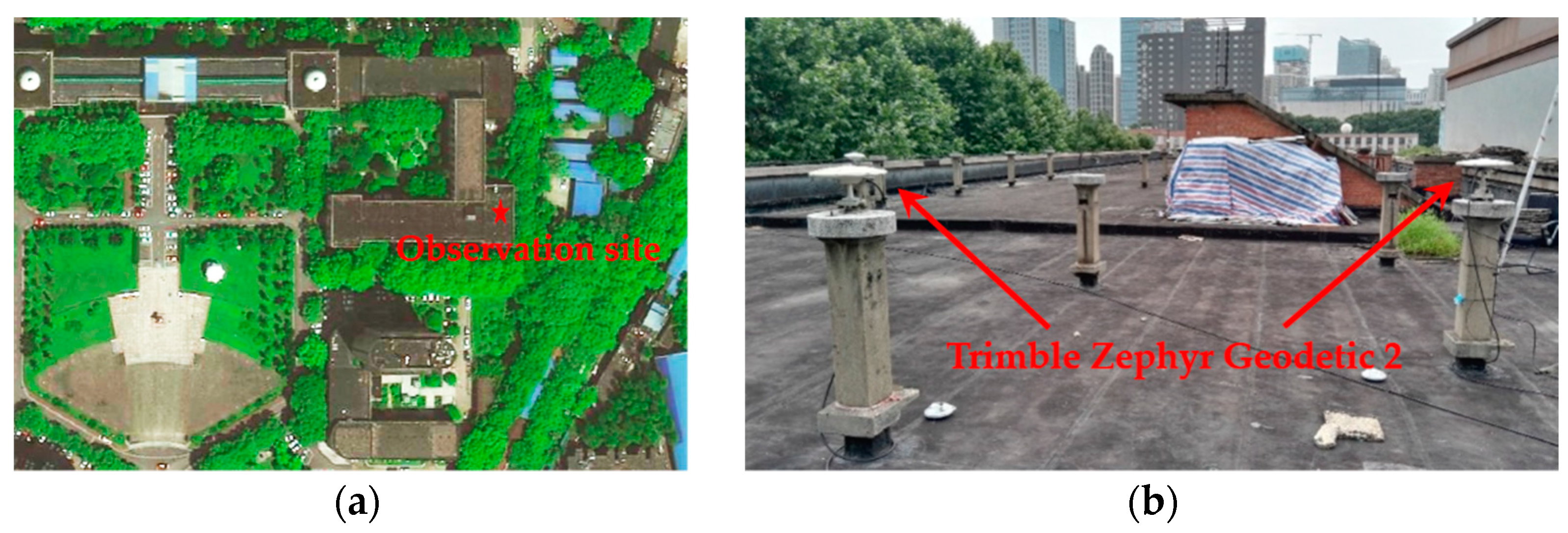
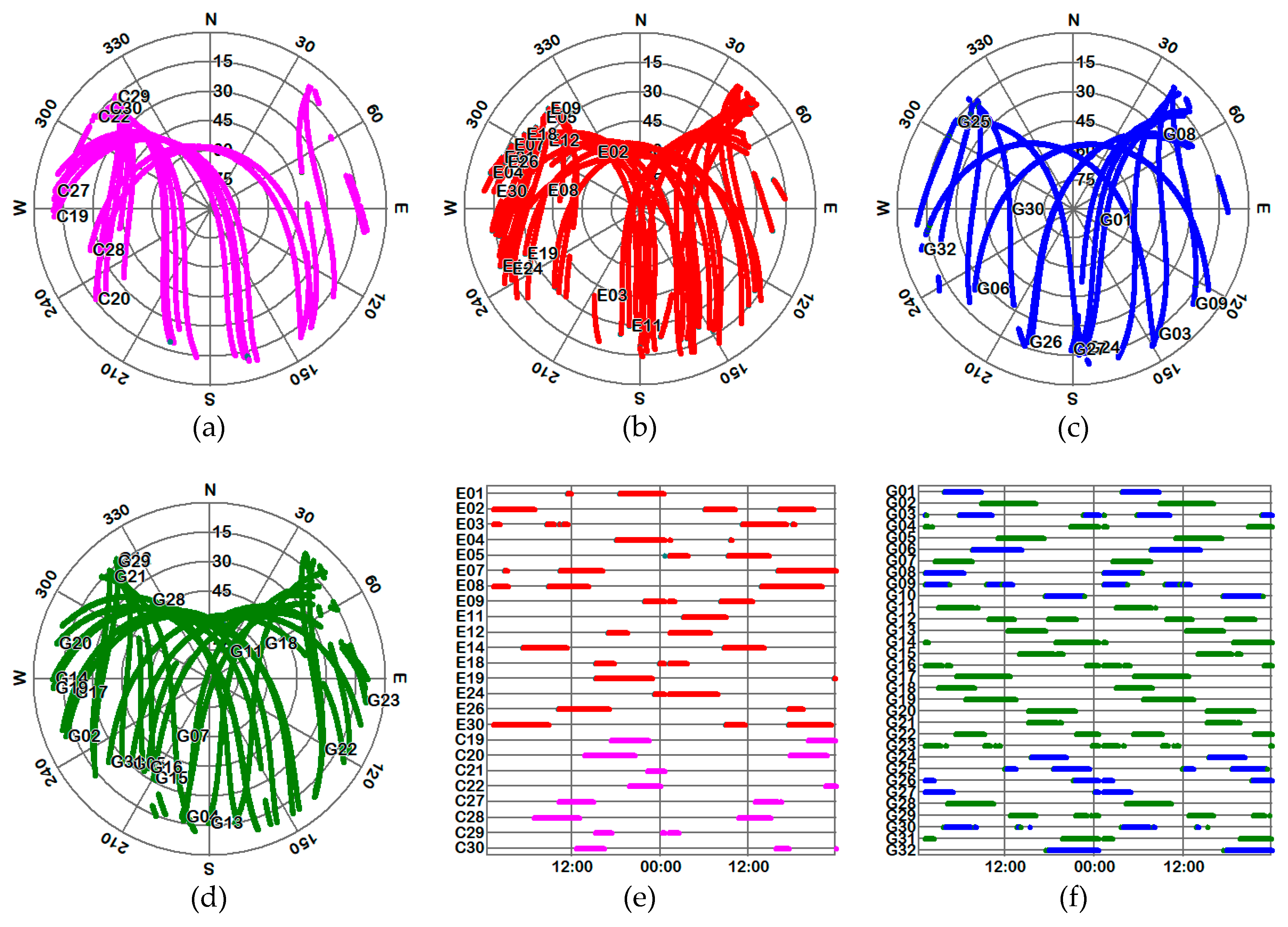
2. Data Collection
3. Quality Assessment of the B1C/B2a Signals from BDS-3 Operational Satellites
3.1. Carrier-to-Noise Density Ratio (C/N0)
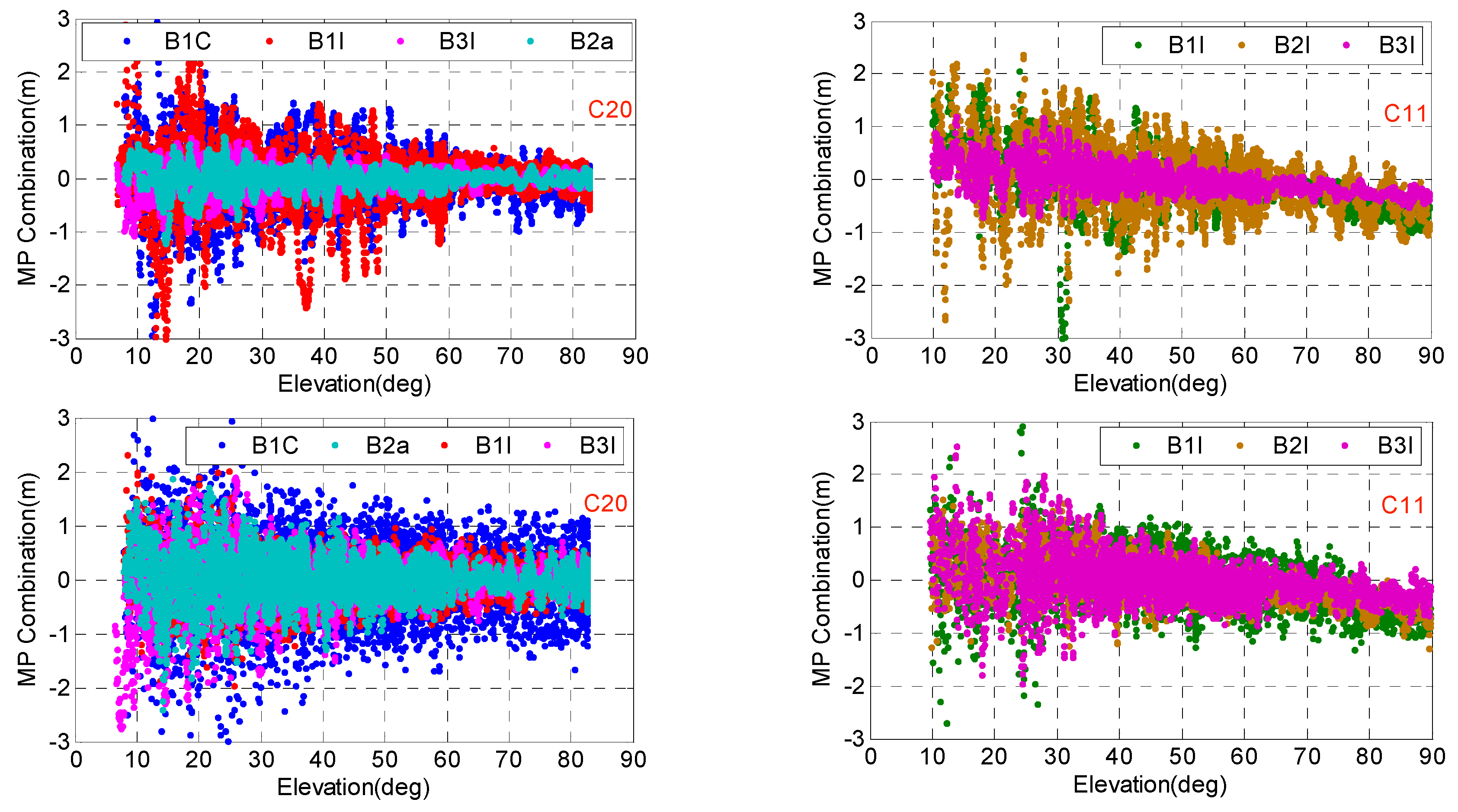
3.2. Pseudorange Multipath and Noise
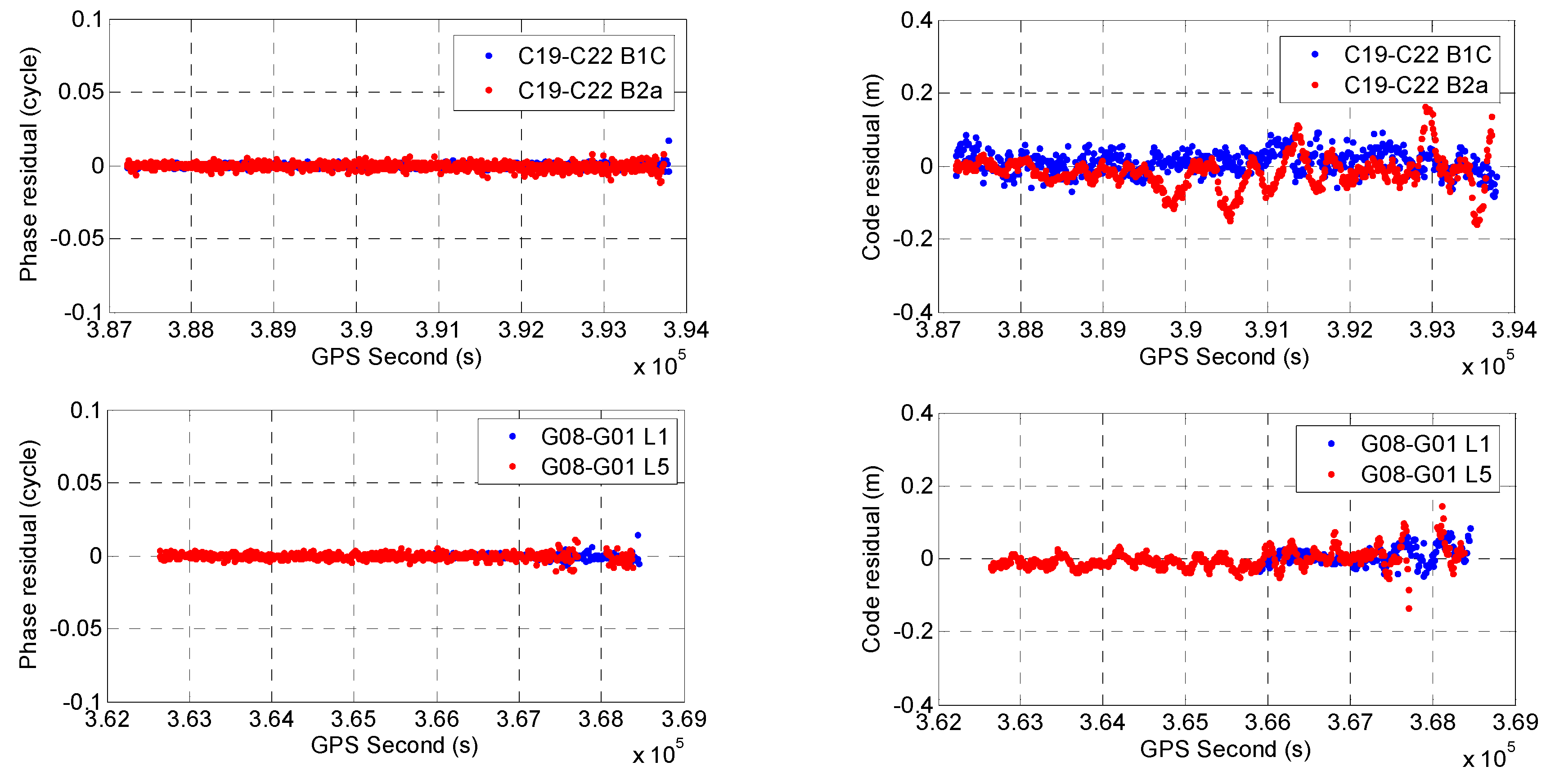
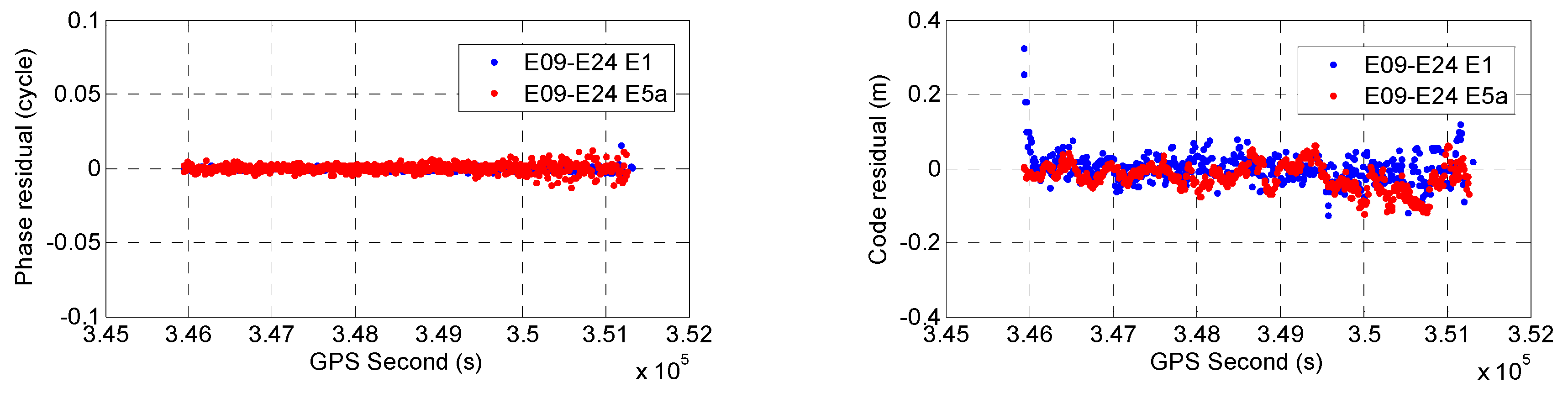
3.3. Zero-Baseline Double-Differenced Carrier Phase and Code Residuals
4. Differential ISB Estimation and Performance Evaluation of Tightly Combined RTK with BDS-3, GPS, and Galileo
4.1. Observation Models for Combined BDS-3, GPS, and Galileo RTK
4.1.1. Intra-System Double-Differenced Observations with Loosely Combined Model (LCM)
4.1.2. Differential ISBs Estimation with Tightly Combined Model (TCM)
4.1.3. Differential ISBs Correction with TCM
4.1.4. Stochastic Model
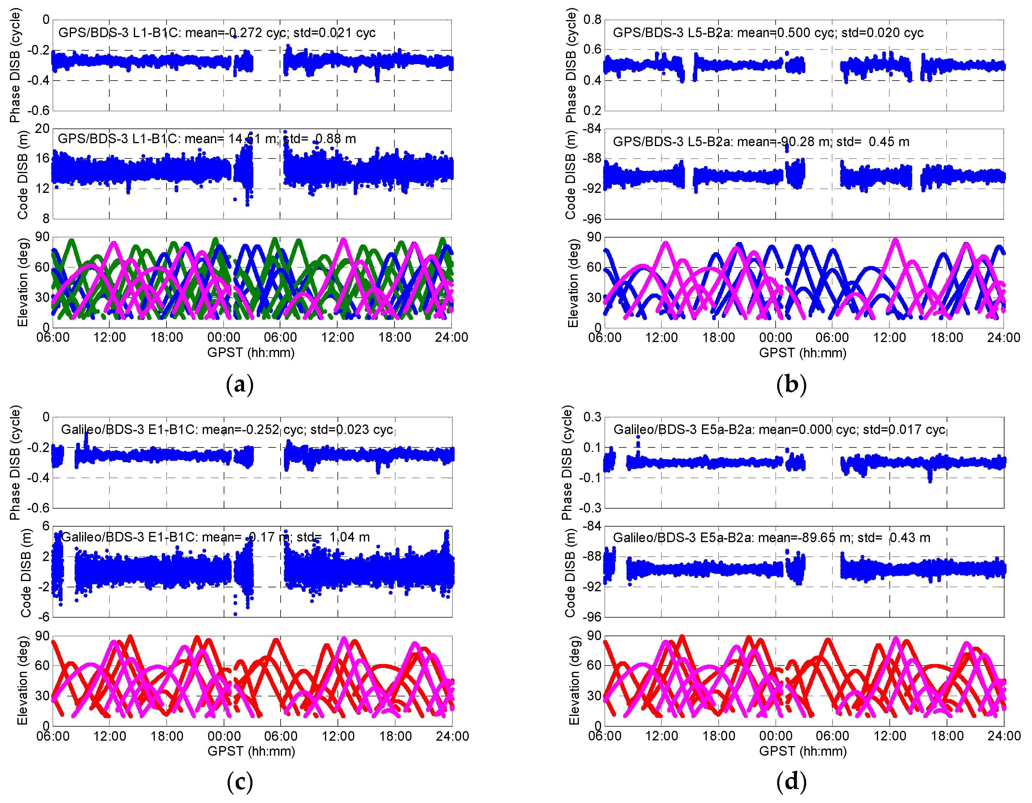
4.2. Differential ISB estimation between BDS-3/GPS/Galileo B1C-L1-E1 and B2a-L5-E5a signals
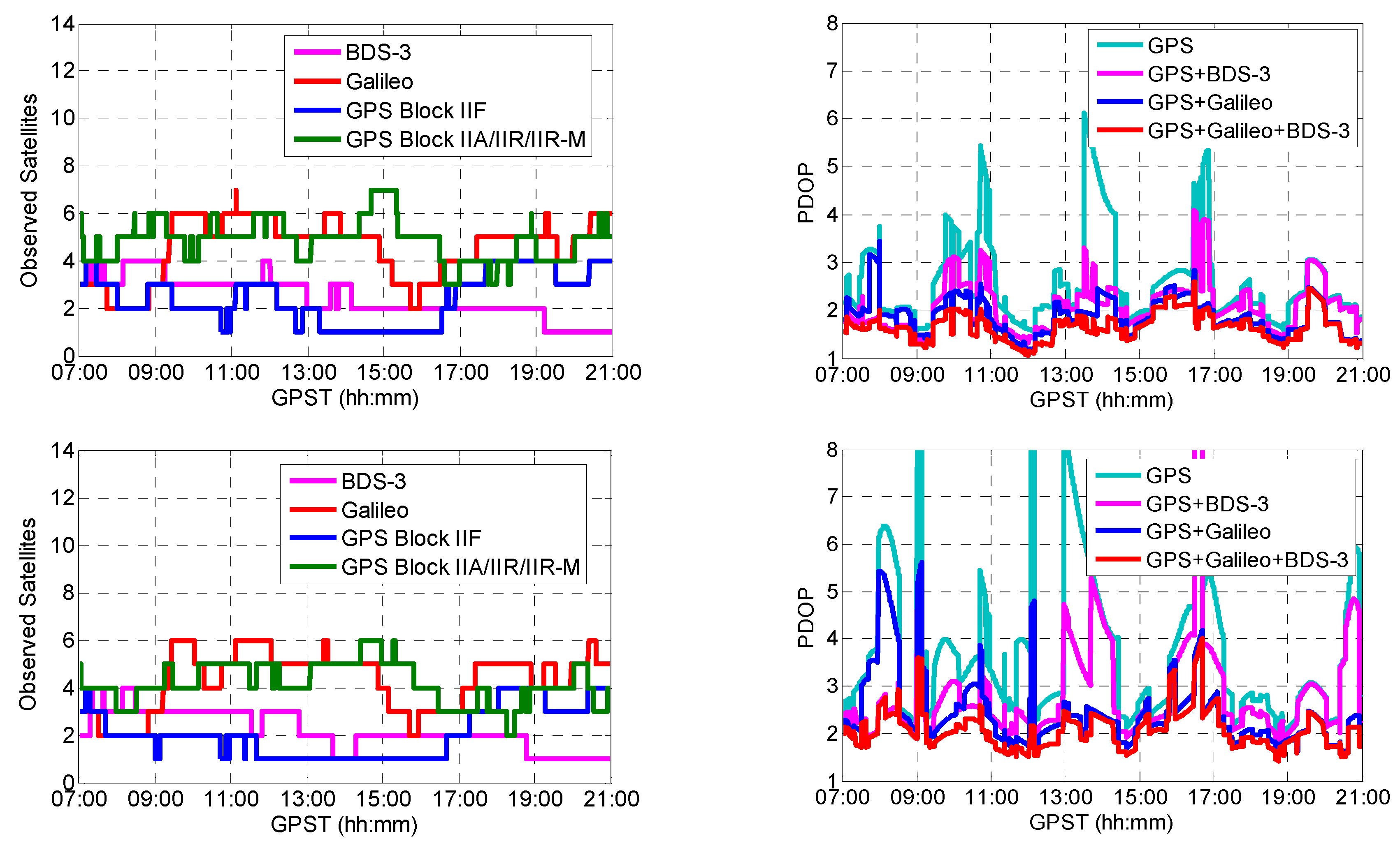
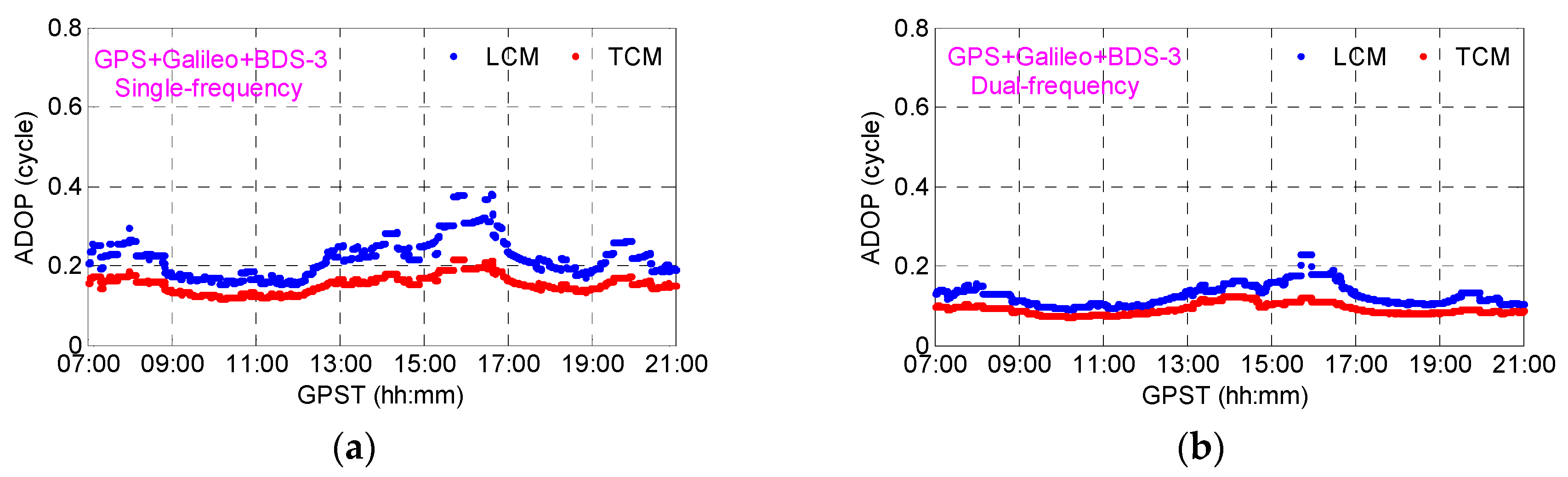
4.3. Initial Assessment of Instantaneous Tightly Combined RTK with GPS, Galileo, and BDS-3 Operational Satellites
4.3.1. Evaluation Statistics
4.3.2. Test Results
5. Conclusions
Author Contributions
Funding
Acknowledgments
Conflicts of Interest
References
- Yang, Y.; Gao, W.; Guo, S.; Mao, Y.; Yang, Y. Introduction to BeiDou-3 navigation satellite system. Navigation 2019, 66, 7–18. [Google Scholar] [CrossRef]
- Yang, Y.; Xu, Y.; Li, J.; Yang, C. Progress and performance evaluation of BeiDou global navigation satellite system: Data analysis based on BDS-3 demonstration system. Sci. Chin. Earth Sci. 2018, 61, 614–624. [Google Scholar] [CrossRef]
- Xie, X.; Fang, R.; Geng, T.; Wang, G.; Zhao, Q.; Liu, J. Characterization of GNSS signals tracked by the iGMAS network considering recent BDS-3 satellites. Remote Sens. 2018, 10, 1736–1749. [Google Scholar] [CrossRef]
- China Satellite Navigation Office (CSNO). Development of the BeiDou Navigation Satellite System (Version 3.0). Available online: http://www.beidou.gov.cn/xt/gfxz/201812/P020190117356.387956569.pdf (accessed on 27 December 2018).
- IGS MGEX BeiDou. Available online: http://mgex.igs.org/IGS_MGEX_Status_BDS.php (accessed on 2 June 2019).
- Lu, M.; Li, W.; Yao, Z.; Cui, X. Overview of BDS III new signals. Navigation 2019, 66, 19–35. [Google Scholar] [CrossRef] [Green Version]
- Zhang, X.; Wu, M.; Liu, W.; Li, X.; Yu, S.; Lv, C.; Wickert, J. Initial assessment of the COMPASS/BeiDou-3: New-generation navigation signals. J. Geod. 2017, 91, 1225–1240. [Google Scholar] [CrossRef]
- Xie, X.; Geng, T.; Zhao, Q.; Liu, J.; Wang, B. Performance of BDS-3: Measurement quality analysis, precise orbit and clock determination. Sensors 2017, 17, 1233–1246. [Google Scholar] [CrossRef] [PubMed]
- Zhou, R.; Hu, Z.; Zhao, Q.; Li, P.; Wang, W.; He, C.; Cai, C.; Pan, Z. Elevation-dependent pseudorange variation characteristics analysis for the new-generation BeiDou satellite navigation system. GPS Solut. 2018, 22, 60–70. [Google Scholar] [CrossRef]
- Zhang, X.; Li, X.; Lv, C.; Wu, M.; Pan, L. A comprehensive analysis of satellite-induced code bias for BDS-3 satellites and signals. Adv. Space Res. 2019, 63, 2822–2835. [Google Scholar] [CrossRef]
- Li, X.; Xie, W.; Huang, J.; Ma, T.; Zhang, X.; Yuan, Y. Estimation and analysis of differential code biases for BDS3/BDS2 using iGMAS and MGEX observations. J. Geod. 2019, 93, 419–435. [Google Scholar] [CrossRef]
- Lv, Y.; Geng, T.; Zhao, Q.; Liu, J. Characteristics of BeiDou-3 experimental satellite clocks. Remote Sens. 2018, 10, 1847–1859. [Google Scholar] [CrossRef]
- Wu, Z.; Zhou, S.; Hu, X.; Liu, L.; Shuai, T.; Xie, Y.; Tang, C.; Pan, J.; Zhu, L.; Chang, Z. Performance of the BDS3 experimental satellite passive hydrogen maser. GPS Solut. 2018, 22, 43–55. [Google Scholar] [CrossRef]
- Zhang, R.; Tu, R.; Liu, J.; Hong, J.; Fan, L.; Zhang, P.; Lu, X. Impact of BDS-3 experimental satellites to BDS-2: Service area, precise products, precise positioning. Adv. Space Res. 2018, 62, 829–844. [Google Scholar] [CrossRef]
- Li, X.; Yuan, Y.; Zhu, Y.; Huang, J.; Wu, J.; Xiong, Y.; Zhang, X.; Li, X. Precise orbit determination for BDS3 experimental satellites using iGMAS and MGEX tracking networks. J. Geod. 2019, 93, 103–117. [Google Scholar] [CrossRef]
- Yang, Y.; Huang, G.; Zhang, Q.; Liu, C.; Wang, L.; Qin, Z. Early analysis of precise orbit and clock offset determination for the satellites of the global BeiDou-3 system. Adv. Space Res. 2019, 63, 1270–1279. [Google Scholar]
- Odijk, D.; Teunissen, P.J.G. Characterization of between receiver GPS-Galileo inter-system biases and their effect on mixed ambiguity resolution. GPS Solut. 2013, 17, 521–533. [Google Scholar] [CrossRef]
- Paziewski, J.; Wielgosz, P. Accounting for Galileo–GPS inter-system biases in precise satellite positioning. J. Geod. 2015, 89, 81–93. [Google Scholar] [CrossRef]
- Yuan, Y.; Zhang, B. Retrieval of inter-system biases (ISBs) using a network of multi-GNSS receivers. J. Glob. Position Syst. 2014, 13, 22–29. [Google Scholar]
- Paziewski, J.; Sieradzki, R.; Wielgosz, P. Selected properties of GPS and Galileo-IOV receiver intersystem biases in multi-GNSS data processing. Meas. Sci. Technol. 2015, 26, 095008. [Google Scholar] [CrossRef]
- Odolinski, R.; Teunissen, P.J.G.; Odijk, D. Combined BDS, Galileo, QZSS and GPS single-frequency RTK. GPS Solut. 2015, 19, 151–163. [Google Scholar] [CrossRef]
- Odijk, D.; Nadarajah, N.; Zaminpardazm, S.; Teunissen, P.J.G. GPS, Galileo, QZSS and IRNSS differential ISBs: Estimation and application. GPS Solut. 2016, 21, 439–450. [Google Scholar] [CrossRef]
- Paziewski, J.; Wielgosz, P. Investigation of some selected strategies for multi-GNSS instantaneous RTK positioning. Adv. Space Res. 2017, 59, 12–23. [Google Scholar] [CrossRef]
- Wu, M.; Zhang, X.; Liu, W.; Ni, S.; Yu, S. Tightly combined BeiDou B2 and Galileo E5b signals for precise relative positioning. J. Navigation. 2017, 70, 1253–1266. [Google Scholar] [CrossRef]
- Li, G.; Geng, J.; Guo, J.; Zhou, S.; Lin, S. GPS+ Galileo tightly combined RTK positioning for medium-to-long baselines based on partial ambiguity resolution. J. Glob. Position Syst. 2018, 16, 3–12. [Google Scholar] [CrossRef]
- Gao, W.; Gao, C.; Pan, S.; Meng, X.; Xia, Y. Inter-system differencing between GPS and BDS for medium-baseline RTK positioning. Remote Sens. 2017, 9, 948–964. [Google Scholar] [CrossRef]
- Gao, W.; Meng, X.; Gao, C.; Pan, S.; Wang, D. Combined GPS and BDS for single-frequency continuous RTK positioning through real-time estimation of differential inter-system biases. GPS Solut. 2018, 22, 20–33. [Google Scholar] [CrossRef]
- Kubo, N.; Tokura, H.; Pullen, S. Mixed GPS-BeiDou RTK with inter-systems bias estimation aided by CSAC. GPS Solut. 2018, 22, 5–16. [Google Scholar] [CrossRef]
- Sui, X.; Shi, C.; Xu, A. The Stability of GPS/BDS inter-system biases at the receiver end and its effect on ambiguity resolution. Geomat. Inf. Sci. Wuhan Univ. 2018, 43, 175–182. [Google Scholar]
- Liu, J.; Tu, R.; Han, J.; Zhang, R.; Zhang, P.; Fan, L.; Lu, X. Inter-system biases in GPS and BDS combined relative positioning by double-differenced observations. Meas. Sci. Technol. 2019, in press. [Google Scholar]
- Zaminpardaz, S.; Teunissen, P.J.G. Analysis of Galileo IOV+ FOC signals and E5 RTK performance. GPS Solut. 2017, 21, 1855–1870. [Google Scholar] [CrossRef]
- Paziewski, J.; Sieradzki, R.; Wielgosz, P. On the applicability of Galileo FOC satellites with incorrect highly eccentric orbits: An evaluation of instantaneous medium-range positioning. Remote Sens. 2018, 10, 208–236. [Google Scholar] [CrossRef]
- Estey, L.H.; Meertens, C.M. TEQC: The multi-purpose toolkit for GPS/GLONASS data. GPS Solut. 1999, 3, 42–49. [Google Scholar] [CrossRef]
- Wanninger, L.; Beer, S. BeiDou satellite-induced code pseudorange variations: Diagnosis and therapy. GPS Solut. 2015, 19, 639–648. [Google Scholar] [CrossRef]
- Amiri-Simkooei, A.R.; Tiberius, C.C.J.M. Assessing receiver noise using GPS short baseline time series. GPS Solut. 2007, 11, 21–35. [Google Scholar] [CrossRef]
- Wu, M.; Zhang, X.; Liu, W.; Wu, R.; Zhang, R.; Le, Y.; Wu, Y. Influencing factors of differential inter-system bias and performance assessment of tightly combined GPS, Galileo, and QZSS relative positioning for short baseline. J. Navigation. 2019, 72, 965–986. [Google Scholar] [CrossRef]
- Odolinski, R.; Teunissen, P.J.G. Low-cost, 4-system, precise GNSS positioning: A GPS, Galileo, BDS and QZSS ionosphere-weighted RTK analysis. Meas. Sci. Technol. 2017, 28, 125801. [Google Scholar] [CrossRef]
- Odolinski, R.; Teunissen, P.J.G. Low-cost, high-precision, single-frequency GPS-BDS RTK positioning. GPS Solut. 2017, 21, 1315–1330. [Google Scholar] [CrossRef]
- Teunissen, P.J.G. A canonical theory for short GPS baselines. Part IV: Precision versus reliability. J. Geod. 1997, 71, 513–525. [Google Scholar] [CrossRef]
- Odijk, D.; Teunissen, P.J.G. ADOP in closed form for a hierarchy of multi-frequency single-baseline GNSS models. J. Geod. 2008, 82, 473–492. [Google Scholar] [CrossRef] [Green Version]
- Teunissen, P.J.G.; Odolinski, R.; Odijk, D. Instantaneous BeiDou+ GPS RTK positioning with high cut-off elevation angles. J. Geod. 2014, 88, 335–350. [Google Scholar] [CrossRef]
- Teunissen, P.J.G. Least squares estimation of the integer GPS ambiguities. In Proceedings of the General Meeting of the IAG, Beijing, China, 8–13 August 1995. [Google Scholar]
- Verhagen, S. The GNSS integer ambiguities: Estimation and validation. PhD Thesis, Delft University of Technology, Delft, The Netherlands, 2005. [Google Scholar]
- Verhagen, S.; Teunissen, P.J.G. The ratio test for future GNSS ambiguity resolution. GPS Solut. 2013, 17, 535–548. [Google Scholar] [CrossRef]


| SVN | RRN | Common Name | COSPAR ID | NORAD ID | Launch Time | Orbit |
|---|---|---|---|---|---|---|
| C201 | C19 1 | BDS-3 MEO-1 | 2017-069A | 43001 | 5.11.2017 | MEO |
| C202 | C20 | BDS-3 MEO-2 | 2017-069B | 43002 | 5.11.2017 | MEO |
| C203 | C27 | BDS-3 MEO-7 | 2018-003A | 43107 | 11.01.2018 | MEO |
| C204 | C28 2 | BDS-3 MEO-8 | 2018-003B | 43108 | 11.01.2018 | MEO |
| C205 | C22 | BDS-3 MEO-4 | 2018-018A | 43207 | 12.02.2018 | MEO |
| C206 | C21 | BDS-3 MEO-3 | 2018-018B | 43208 | 12.02.2018 | MEO |
| C207 | C29 | BDS-3 MEO-9 | 2018-029A | 43245 | 29.03.2018 | MEO |
| C208 | C30 | BDS-3 MEO-10 | 2018-029B | 43246 | 29.03,2018 | MEO |
| C209 | C23 | BDS-3 MEO-5 | 2018-062A | 43581 | 29.07.2018 | MEO |
| C210 | C24 | BDS-3 MEO-6 | 2018-062B | 43582 | 29.07.2018 | MEO |
| C211 | C26 | BDS-3 MEO-11 | 2018-067A | 43602 | 24.08.2018 | MEO |
| C212 | C25 | BDS-3 MEO-12 | 2018-067B | 43603 | 24.08.2018 | MEO |
| C213 | C32 | BDS-3 MEO-13 | 2018-072A | 43622 | 19.09.2018 | MEO |
| C214 | C33 | BDS-3 MEO-14 | 2018-072B | 43623 | 19.09.2018 | MEO |
| C215 | C35 | BDS-3 MEO-16 | 2018-078A | 43647 | 15.10.2018 | MEO |
| C216 | C34 | BDS-3 MEO-15 | 2018-078B | 43648 | 15.10.2018 | MEO |
| C217 | C59 | BDS-3 GEO-1 | 2018-085A | 43683 | 1.11.2018 | GEO |
| C218 | C36 | BDS-3 MEO-17 | 2018-093A | 43706 | 18.11.2018 | MEO |
| C219 | C37 | BDS-3 MEO-18 | 2018-093B | 43707 | 18.11.2018 | MEO |
| C220 | C38 | BDS-3 IGSO-1 | 2019-023A | 44204 | 20.04.2019 | IGSO |
| Band | Frequency (MHZ) | Signal Component | Modulation | Code Rate (Mcps) |
|---|---|---|---|---|
| B1 | 1575.42 | B1CD | 1 BOC (1,1) | 1.023 |
| B1CP | 2 QMBOC (6,1,4/33) | 1.023 | ||
| 1561.098 | B1I | 3 BPSK (2) | 2.046 | |
| B2 | 1176.45 | B2aD | 4 QPSK (10) | 10.23 |
| B2aP | 10.23 | |||
| 1207.14 | B2bI | QPSK (10) | 10.23 | |
| B2bQ | 10.23 | |||
| B3 | 1268.52 | B3I | BPSK (10) | 10.23 |
| Receiver | GPS | Galileo | BDS-3 | |||
|---|---|---|---|---|---|---|
| iGMAS | L1 C/A | L5I | E1B | E5aI | B1C Data | B2a Data |
| M300Pro | L1 C/A | L5I | E1 (B + C) | E5a (I + Q) | B1CC 1 | B2aA 2 |
| Freq. | Ratio | GPS/BDS-3 (Epoch) | GPS/Galileo/BDS-3 (Epoch) | ||||
|---|---|---|---|---|---|---|---|
| LCM | TCM | Imp. 3 | LCM | TCM | Imp. | ||
| SF 1 | ≥2.0 | 1941 | 3084 | 58.9% | 4004 | 4805 | 20.0% |
| ≥3.0 | 1087 | 2114 | 94.5% | 3108 | 4523 | 45.5% | |
| ≥5.0 | 450 | 1133 | 151.8% | 1782 | 3616 | 102.9% | |
| DF 2 | ≥2.0 | 3607 | 4387 | 21.6% | 4922 | 4978 | 1.1% |
| ≥3.0 | 3005 | 4015 | 33.6% | 4800 | 4888 | 1.8% | |
| ≥5.0 | 2088 | 3337 | 59.8% | 4334 | 4602 | 6.2% | |
| Freq. | Elev. | AVE. SAT. | AR Validation | GPS/BDS-3 | GPS/Galileo/BDS-3 | ||||
|---|---|---|---|---|---|---|---|---|---|
| LCM | TCM | Imp. 2 | LCM | TCM | Imp. | ||||
| SF | 10° | (9.3, 13.1) | Th 1 = 2.0 | 33.2 | 58.7 | 25.5 | 78.4 | 95.1 | 16.7 |
| Th = 3.0 | 19.7 | 40.8 | 21.1 | 60.6 | 89.4 | 28.8 | |||
| Pf = 1% | 9.8 | 39.5 | 29.7 | 71.8 | 97.5 | 25.7 | |||
| Pf = 0.1% | 0.1 | 14.5 | 14.4 | 43.5 | 93.9 | 50.4 | |||
| 20° | (8.0, 11.6) | Th = 2.0 | 24.1 | 47.3 | 23.2 | 66.8 | 91.4 | 24.6 | |
| Th = 3.0 | 14.7 | 34.5 | 19.8 | 49.8 | 84.5 | 34.7 | |||
| Pf = 1% | 3.3 | 22.3 | 19.0 | 51.0 | 93.2 | 42.2 | |||
| Pf = 0.1% | 0.0 | 5.8 | 5.8 | 23.6 | 84.5 | 60.9 | |||
| DF | 10° | (9.3, 13.1) | Th = 2.0 | 68.7 | 85.9 | 17.2 | 97.6 | 98.7 | 1.1 |
| Th = 3.0 | 58.2 | 79.2 | 21.0 | 95.1 | 96.9 | 1.8 | |||
| Pf = 1% | 63.2 | 84.8 | 21.6 | 99.2 | 100.0 | 0.8 | |||
| Pf = 0.1% | 53.6 | 79.0 | 25.4 | 97.2 | 100.0 | 2.8 | |||
| 20° | (8.0, 11.6) | Th = 2.0 | 59.1 | 80.1 | 21.0 | 95.1 | 96.9 | 1.8 | |
| Th = 3.0 | 48.8 | 73.4 | 24.6 | 92.8 | 96.4 | 3.6 | |||
| Pf = 1% | 50.6 | 78.9 | 28.3 | 96.3 | 97.5 | 1.2 | |||
| Pf = 0.1% | 35.5 | 70.1 | 34.6 | 93.2 | 97.5 | 4.3 | |||
| Freq. | Model | 10° | 20° | ||||
|---|---|---|---|---|---|---|---|
| E (cm) | N (cm) | U (cm) | E (cm) | N (cm) | U (cm) | ||
| SF | GB 1 LCM | 62.5/0.3 | 86.3/0.3 | 157.0/0.9 | 63.6/0.3 | 89.7/0.3 | 212.3/1.0 |
| GB TCM | 58.2/0.3 | 82.6/0.3 | 156.0/0.9 | 60.6/0.3 | 85.6/0.4 | 199.0/1.0 | |
| GEB 2 LCM | 53.6/0.2 | 70.3/0.3 | 134.8/0.8 | 55.5/0.2 | 71.4/0.3 | 160.6/0.8 | |
| GEB TCM | 49.5/0.2 | 67.3/0.3 | 130.7/0.9 | 52.0/0.2 | 68.6/0.3 | 154.0/0.9 | |
| DF | GB LCM | 54.5/0.2 | 75.0/0.3 | 137.6/0.8 | 55.2/0.2 | 76.4/0.3 | 177.3/0.8 |
| GB TCM | 48.3/0.3 | 65.9/0.3 | 130.9/1.0 | 48.9/0.3 | 66.7/0.3 | 158.9/1.0 | |
| GEB LCM | 39.5/0.3 | 48.9/0.3 | 102.9/0.9 | 40.7/0.3 | 49.5/0.3 | 118.0/0.9 | |
| GEB TCM | 35.6/0.2 | 45.7/0.3 | 93.4/0.8 | 36.3/0.2 | 46.3/0.3 | 105.8/0.8 | |
© 2019 by the authors. Licensee MDPI, Basel, Switzerland. This article is an open access article distributed under the terms and conditions of the Creative Commons Attribution (CC BY) license (http://creativecommons.org/licenses/by/4.0/).
Share and Cite
Wu, M.; Liu, W.; Wang, W.; Zhang, X. Differential Inter-System Biases Estimation and Initial Assessment of Instantaneous Tightly Combined RTK with BDS-3, GPS, and Galileo. Remote Sens. 2019, 11, 1430. https://doi.org/10.3390/rs11121430
Wu M, Liu W, Wang W, Zhang X. Differential Inter-System Biases Estimation and Initial Assessment of Instantaneous Tightly Combined RTK with BDS-3, GPS, and Galileo. Remote Sensing. 2019; 11(12):1430. https://doi.org/10.3390/rs11121430
Chicago/Turabian StyleWu, Mingkui, Wanke Liu, Wang Wang, and Xiaohong Zhang. 2019. "Differential Inter-System Biases Estimation and Initial Assessment of Instantaneous Tightly Combined RTK with BDS-3, GPS, and Galileo" Remote Sensing 11, no. 12: 1430. https://doi.org/10.3390/rs11121430