Article

Improving the GNSS-R Specular Reflection Point Positioning Accuracy Using the Gravity Field Normal Projection Reflection Reference Surface Combination Correction Method

1
Qian Xuesen Laboratory of Space Technology, China Academy of Space Technology, Beijing 100094, China
2
College of Astronautics, Nanjing University of Aeronautics and Astronautics, Nanjing 210016, China
*
Authors to whom correspondence should be addressed.
Remote Sens. 2019, 11(1), 33; https://doi.org/10.3390/rs11010033
Submission received: 20 November 2018 / Revised: 14 December 2018 / Accepted: 18 December 2018 / Published: 26 December 2018
(This article belongs to the Special Issue Radar Remote Sensing of Oceans and Coastal Areas)

Abstract

:
Global Navigation Satellite System Reflectometry (GNSS-R) is of great significance for the extraction and research of precise information of sea surface topography. Improving measurement accuracy is necessary for realizing spaceborne GNSS-R sea surface altimetry application. The main error source of GNSS-R distance measurement is the error of the specular reflection point positioning, which directly affects the sea surface altimetry accuracy on the reference datum. There is an elevation error of several tens of meters between the reflection reference surface used by the existing specular reflection point geometric positioning methods and the sea surface elevation, which is importantly influenced by the earth’s gravity field. Therefore, the gravity field reflection reference surface correction is the key to improving the specular reflection point positioning accuracy. In this study, based on the correction of the GNSS-R reflection reference surface, research on improving the positioning accuracy of the specular reflection point is carried out. Firstly, in order to reduce the positioning error caused by the elevation difference between the reflection reference surface and the sea surface, the gravity field reflection reference surface correction method (GFRRSCM) which corrects the reflection reference surface from the WGS-84 ellipsoid to geoid is proposed, and the positioning accuracy is improved by 25.15 m. Secondly, the normal projection reflection reference surface correction method (NPRRSCM) is proposed to correct the specular reflection point determined by the GFRRSCM from the reflection reference plane of the radial to that of the normal. Additionally, in the process of solving the spatial geometric relationship of the reflection path, the approximate substitution error is reduced by directly solving the normal projection on the plane, and the positioning accuracy is further improved by 13.05 m towards the normal. Thirdly, based on the gravity field normal projection reflection reference surface combination correction method (GF-NPRRSCCM), the specular reflection point positioning accuracy is synthetically improved by 28.66 m.

Graphical Abstract

1. Introduction

As a new technology of microwave remote sensing, Global Navigation Satellite System Reflectometry (GNSS-R) has advantages such as abundant signal source, low cost, low power consumption, all-day, all-weather, and it can acquire various global ocean dynamics and environmental parameters such as Sea Surface Height (SSH), sea surface wind field, sea ice, and ocean salinity with high spatiotemporal resolution [1]. In 1993, Martin Neria first proposed the feasibility of using Global Positioning System (GPS) reflected signals for altimetry [2]. In 1994, Auber detected the GNSS-R signal for the first time in the data of a receiver used in an aircraft test in July 1991 [3]. In 1996, NASA first proposed that GNSS-R can be applied to sea state remote sensing and developed a delay mapping receiver [4,5,6]. In 2000, Zavorotny and Voronovich gave a theoretical model (Z-V model) of sea surface reflection signals [7]. From 1997 to 2002, the Martin Neria team, the Jet Propulsion Laboratory (JPL) and the European Space Agency (ESA) conducted several shore-based and air-based GNSS-R altimetry experiments, many of which achieved accuracy at the centimeter level [8,9,10,11,12]. In 2003, Hajj et al. [13] gave systematic analysis of elevation measurements using GPS reflected signals. For the space-based GNSS-R, in 2002, Lowe [14] detected the reflected signal of GPS in the data collected by the Spaceborne Imaging Radar C-band (SIR-C). From 2001 to 2004, Beyerle found GPS reflection signals in the data collected by the Low Earth orbit (LEO) satellite of the Challenging Minisatellite Payload (CHAMP) mission [15,16]. In 2003 and 2014, the GNSS-R receiving equipment by the British Surrey Satellite Technology Ltd. were loaded on the UK Disaster Monitoring Constellation (UK-DMC) mission and the TechDemoSat-1 (TDS-1) mission, with observations of the sea surface wind field obtained [17,18]. In 2016, Clarizia [19] carried out the first spaceborne observation of SSH using GPS-R data from the TDS-1 satellite. In 2016, NASA launched the Cyclone Global Navigation Satellite System (CYGNSS) mission consisting of eight small satellites with the goal of tracking and monitoring the mid–low latitude surface wind field [20,21].
To date, the application of the high-temporal resolution observation capability of the GNSS-R satellites for sea surface wind research is relatively more often [17,18,20,21], but the application of spaceborne GNSS-R high-spatial resolution observation capability for global SSH research is relatively rare [19]. Our research team of navigation and detection based on the information of aerospace-aeronautics-marine integration (http://www.qxslab.cn/ndia/) of Qian Xuesen Laboratory of Space Technology has carried out preliminary exploration research on the theory, method, and key technology of improving underwater gravity matching navigation accuracy based on the GNSS-R altimetry constellation principle. Underwater gravity matching navigation is an effective method to correct the drift error of the submersible inertial navigation system [22], therefore, the construction of a global, high-spatial-resolution and high-accuracy ocean gravity field reference map is the key to determining the accuracy of underwater navigation [23]. The current conventional means of obtaining the global ocean gravity field is to convert the SSH obtained by the satellite radar altimeter into gravity anomaly, while this study aims to improve the specular reflection point position accuracy for the GNSS-R satellite altimetry, and thus to support the obtention of the high-spatial-resolution and high-accuracy ocean gravity fields. The multi-channel GNSS-R receiver can utilize the abundant signal source of more than 100 satellites of the four international GNSSs to acquire multiple GNSS-R signals simultaneously. Additionally, the cost of the GNSS-R satellite platform and payload are relatively low, thus a ~6–8 satellites constellation can be formed to increase the amount and frequency of observation by several times combined with a parameter optimized design of the dedicated nadir-pointing antenna, orbit, and constellation [24,25]. Therefore, GNSS-R satellite network observation is an effective means to obtain global high-spatial-resolution SSH.
On the other hand, the retrieval of high-accuracy ocean gravity field requires sea surface altimetry to achieve centimeter level accuracy [26]. The GNSS-R sea surface altimetry has strict requirements for path delay error control of signal transmission. The main error sources include the errors of transmission in atmospheric, sea surface scattering and receiving, and processing of the electromagnetic wave signals emitted by GNSS satellites, as well as the errors of positioning the specular reflection point and the receiver nadir point on the complex and changing sea surface [27,28]. The specular reflection point is the point on the reflection surface that minimizes the distance that the GNSS satellite signal reaches the receiver through reflection [1]. The GNSS-R Delay Doppler Map (DDM) which contains the information of the Doppler shift and code phase delay takes the specular reflection point position as standard reference. The position information of the specular reflection point is also used to accurately model the rising edge of the delayed wave [29]. Calculating the SSH according to the Leading Edge Derivative (LED) algorithm requires calculating the time delay of the reflected signal relative to the direct signal based on the positions of the transmitter, the receiver, and the specular reflection point [15,30]. In the case where the error caused by the orbital uncertainty of the GNSS satellite and the receiver is known, the error of the time delay and the length of the reflected signal path are mainly determined by the specular reflection point positioning error at the sea surface and the atmospheric transmission error of the signal [27,28]. In addition, the output signal-to-noise ratio of the dual-base radar system is related to the signal propagation path, which is directly related to the position of the specular reflection point [31]. In sea surface remote sensing applications, the precise position information of the specular reflection points can also be used to determine whether the reflected signal is from the surface of the sea, the land or the ice. The specular reflection point is taken as the reference point of the GNSS-R signal reflection geometry and the relevant parameters, its positioning error affects the accuracy of GNSS-R remote sensing products and the estimation of observation capabilities parameters such as spatiotemporal resolution on the reference datum [32], especially the SSH accuracy which is directly related to the path error.
The specular reflection point positioning methods can be divided into physical methods and geometric methods. The physical methods are based on the processing of the received signals [30], the geometric methods, on which this study carries out research, are based on the geometric conditions that the specular reflection points should satisfy [2,27,28,29,33,34]. At present, the geometric positioning methods of the specular reflection point are mainly the Sien-Chong (S-C) Wu method, the dichotomy, the Wagner method, and the Gleason method. The S-C Wu method has two steps: the first step is to use the spherical surface as the reflection surface to search the rough position of the specular reflection point, and the second step corrects the specular reflection point from the spherical surface to the reference ellipsoid [28]. The dichotomy iteratively searches the position of the specular reflection point on the spherical surface based on solving the zero-crossing solution of the equation by the dichotomy [33]. The Wagner method is based on the premise of the earth standard sphere model, and the geodetic coordinates of the specular reflection point on the spherical surface are obtained by the polar spherical triangle relationship [29,34]. The Gleason method estimates the position of the specular reflection point on the spherical surface based on the vector collinear method [35].
The existing geometric specular reflection point positioning methods take the reference ellipsoid or standard sphere as the reflection reference surface, but do not consider the positioning errors caused by the elevation difference between the sea surface and the reflection reference surface (Figure 1), and this error cannot be ignored. For the approximation of the earth surface, if the WGS-84 ellipsoid is selected, the elevation difference between the ellipsoid surface and the instantaneous sea level is tens of meters, while if global earth gravity model geoid is applied, the accuracy at the sea surface can reach the decimeter level [1].
A number of altimetry experiments by shore-based and air-based GNSS-R equipments on calm lake surface and in specific areas of the sea have been able to obtain measurements with high accuracy comparable to those by satellite altimeters [8,9,10,11,12]. However, the global ocean surface topography and roughness, which are complex and variable, are determined by various ocean dynamic parameters such as ocean gravity field, tidal field, circulation field, and sea surface wind field. The reflection reference surface error would introduce uncertainties to the spaceborne GNSS-R global sea surface altimetry. Clarizia carried out the first spaceborne GPS-R observation of SSH with about 8 m Root Mean Squared Error. The TDS-1 metadata’s specular reflection point position, which is used in Clarizia’s study and taken as reference in this study, takes the WGS-84 ellipsoid as reflection reference surface, resulting in positioning error which is propagated into SSH. Additionally, the GPS-R instruments onboard TDS-1 are not optimized for SSH estimation [19]. Therefore, integrating a variety of ocean dynamic parameters to establish a global all-sea-state reflection reference surface model is not only a basic work to improve the accuracy of sea surface altimetry and other applications of GNSS-R, but also a precondition for exerting its high spatial resolution observation advantage and realizing its application value.
Different from previous studies, this study proposes the gravity field—normal projection reflection reference surface combination correction method (GF-NPRRSCCM). The purpose is establishing the geoid reflection reference surface model to improve the positioning accuracy of the specular reflection point based on one of the important parameters determining the sea surface elevation—the earth’s gravity field. Firstly, the WGS-84 ellipsoid is used as the reflection reference surface to preliminarily position the specular reflection point. Then the elevation correction based on the earth’s gravity field model is introduced in the iteration, so that the reflection reference surface is corrected to geoid. The specular reflection point positioning error caused by the elevation difference between the reflection reference surface and the sea surface is reduced. Secondly, based on the elevation correction, the reflection reference surface is corrected from the radial to the normal of the specular reflection point, reducing the positioning error introduced by the normal-radial difference. Additionally, the influence of the approximate substitution on the positioning accuracy is reduced by directly solving the spatial geometric relationship between the normal projection on the plane and the reflection path. Thirdly, based on the combined application of the above two correction methods, the positioning error caused by the difference between the reflection reference surface and the sea surface is reduced, and the positioning accuracy is improved.

2. Materials and Methods

2.1. Data

2.1.1. TechDemoSat-1 Space GPS Receiver Remote Sensing Instrument Data

Positioning the specular reflection point requires the use of the transmitter and the receiver positions. In order to avoid introducing uncertainties from the orbit simulation, and to facilitate reference, the transmitter and the receiver positions contained in the dataset of the Space GPS Receiver Remote Sensing Instrument (SGR-ReSI) carried by the TDS-1 satellite are used to position specular reflection points which are then compared with those also contained in the dataset. The TDS-1 satellite was launched on 8 July 2014, the orbital altitude is 635 km and the inclination is 98°. The GNSS-R payload of the TDS-1 consists a zenith-pointing antenna for receiving direct GPS signals, a nadir-pointing antenna for receiving reflected GPS signals, and the remote sensing receiver SGR-ReSI, which continuously records the integration midpoint time and the corresponding receiver space coordinates. The SGR-ReSI also records the integration midpoint time of the four reflected signal receiving channels when capturing reflection. These two kinds of integration midpoint times are saved in the Level-1 metadata with the corresponding GPS satellites and the derived specular reflection points space coordinates (the TDS-1 data are obtained from: ftp://ftp.merrbys.co.uk) [36]. For extracting the positions, we need the receiver space coordinates when capturing reflection, these reflections are filtered out when the two kinds of integral midpoint times are the same by comparison. In order to achieve statistically significant results based on sufficient time and space coverage, we used a total of 4,492,927 reflections from all the 9444 tracks of April 2018.
The position of the specular reflection point in the TDS-1 satellite dataset takes the WGS-84 ellipsoid as the reflection reference surface. The calculation method is as follow [36]:
  • Applying the coordinate transformation to scale the WGS-84 ellipsoid to a sphere of unit radius in polar and equatorial axes independently. The positions of the transmitter and the receiver are scaled to the new coordinate system by the same transformation.
  • Then the specular reflection point position is calculated using the standard sphere as the reflection reference surface.
  • The inverse of the coordinate transform is applied to scale back to the original ellipsoid.

2.1.2. Earth Gravitational Model 2008

In this study, the Earth Gravitational Model (EGM) 2008 is used to calculate the geoid undulation for correcting the reflection reference surface. The spatial resolution of the EGM2008 is about 5′ (about 9 km), and the geoid undulation propagated standard deviation is 10.925 cm [37]. This study uses the highest-spatial-resolution model which is interpolated to a 1′ × 1′ grid, the interpolation error does not exceed ±1 mm [38].

2.2. Methodologies

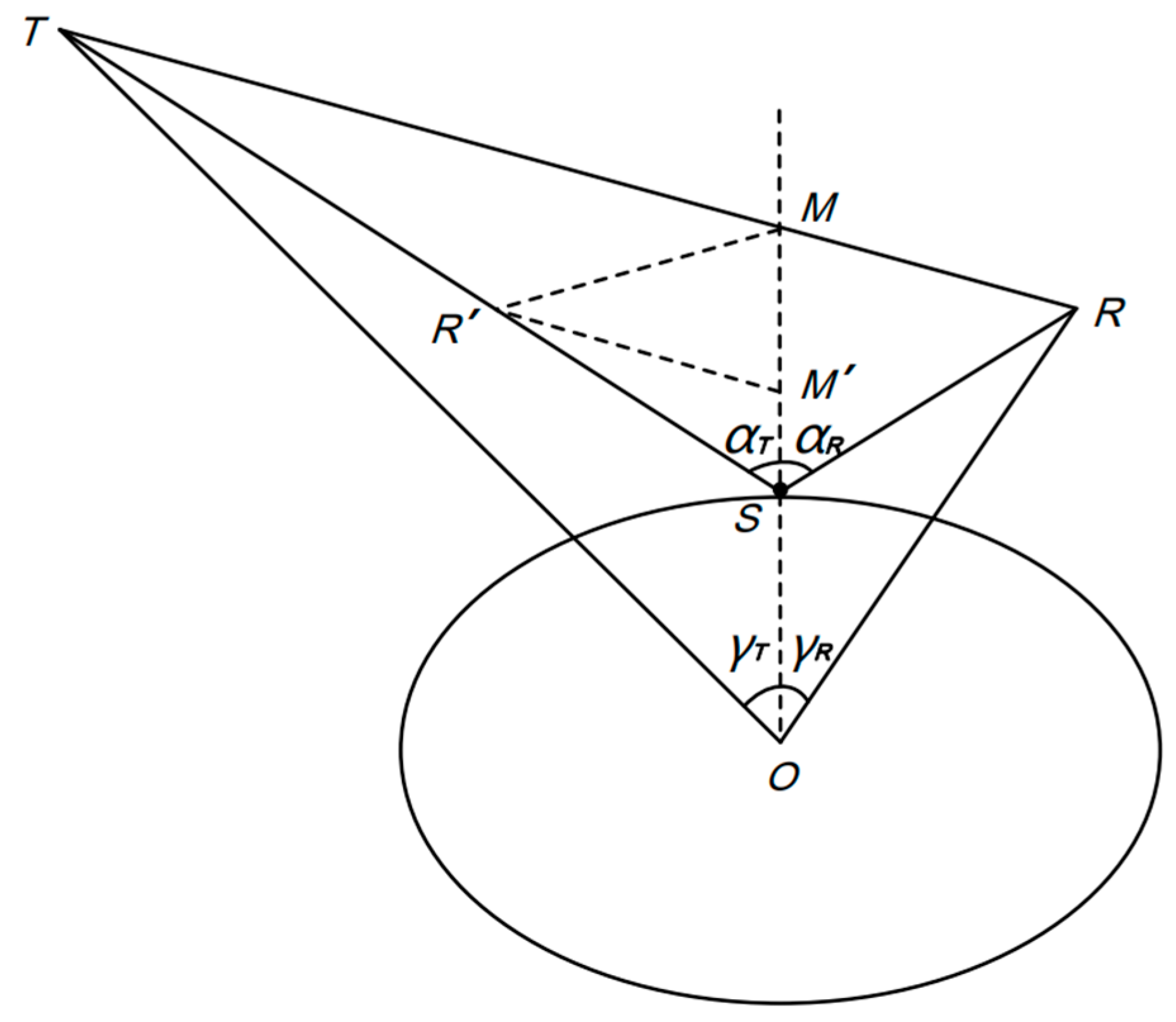
2.2.1. The Gravity Field Reflection Reference Surface Correction Method (GFRRSCM)

The coordinate system of this study is the WGS-84. The S-C Wu method is used to position the specular reflection point with the ellipsoid surface as the reflection reference surface, in each iteration correction, the corresponding geoid undulation of the specular reflection point position is calculated and substituted, and the specular reflection point is finally positioned onto geoid.
The evaluation and comparison of the positioning accuracy of specular reflection point is based on the Fresnel reflection law [2,27,28,29,33,34]. When the positions of the transmitter, the receiver and the reflection reference surface are determined, the angle of incidence, the angle of emergence and the normal of the reflection are determined by the position of the specular reflection point. According to the Fresnel reflection law, the criteria for judging whether the position of the specular reflection point is accurate are as follows: (1) the angle of emergence is equal to the angle of incidence; (2) the normal of the specular reflection point is perpendicular to the reflection surface. Because of the limited accuracy of the computation, the criteria above cannot be fully satisfied, the following standard is used to estimate the positioning accuracy. The smaller the difference between the angle of incidence and the angle of emergence as well as the difference between the normal of the specular reflection point and the vertical direction of the reflection surface, the more accurate the reflection geometric relationship, so that the higher the positioning accuracy of the specular reflection point.
Steps of positioning the specular reflection point are as follows [28]:
1.  Position of M.
In Figure 2, O is the center of the earth, and the position vectors of the receiver, the transmitter, and the specular reflection point are respectively R , T , and S . HR and HT are the geoid undulations of the nadirs of the transmitter and the receiver. M is the intersection of the OS extension line and the TR connection line, R′ is the mirror point of R to OM, and M′ is the mirror point of M to RR′, then:
M = R + H R / ( H R + H T ) ( T R ) ,
2.  Calculation and correction of the initial position of the specular reflection point.
The latitude and the longitude of S are the same as those of M, thus the geoid undulation HS of S can be calculated using EGM2008 model, and then HS is substituted in the conversion of S from the geodetic coordinates system into the space coordinates system, see Equations (2) and (3). Thus, the reflection reference surface is corrected from the ellipsoid towards geoid.
XS = (NS + HS)cos(BS)cos(LS) = NScos(BS)cos(LS) + σx
YS = (NS + HS)cos(BS)sin(LS) = NScos(BS)sin(LS) + σy
ZS = (NS (1 − e2) + HS)sin(BS) = NS(1 − e2) sin(BS) + σz,
where:
N S = a / [ 1 e 2 sin 2 ( B S ) ] ,
in Equation (2), the elevation correction σx, σy, and σz of S in the X, Y, and Z directions are HScos(BS)cos(LS), HScos(BS)sin(LS), HSsin(BS), respectively, and a is the long radius of the WGS-84 ellipsoid. The latitude and the longitude of S are obtained by using the WGS-84 ellipsoid as the reflection reference surface, the space coordinates obtained by this conversion are not based on geoid, hence the following corrections need to be continued.
3.  Calculation of the angle of incidence, the angle of emergence and geocentric.
The geocentric angles γ T and γ R are respectively calculated according to R , S , and T . The angle of incidence α T and the angle of emergence α R of the GPS satellite signals on the reflection surface are respectively calculated according to S R ,   S M , and S T .
4.  Weighted iteration.
Usually, α T and α R are not equal, and they need to be weighted and re-estimated as follows:
α T = α R =   ( H T α T   +   H R α R ) / ( H T   +   H R ) ,
According to the triangle OSR and OST, γ T and γ R are recalculated, respectively, which are recorded as γ T and γ R . The mean of γ T is taken as ( γ T + γ R + γ T γ R )/2, and then M , S ,   α T and α R are recalculated according to the new γ T . The above process is iterated, and the geoid undulation HS of S is introduced to correct in Equation (2) in each iteration until α T = α R , at which S determines the accurate reflection geometric relationship on geoid, meaning that S has been corrected to geoid from the WGS-84 ellipsoid. Seven iterations on average can make the difference between α T and α R less than 10−5 rad [1].

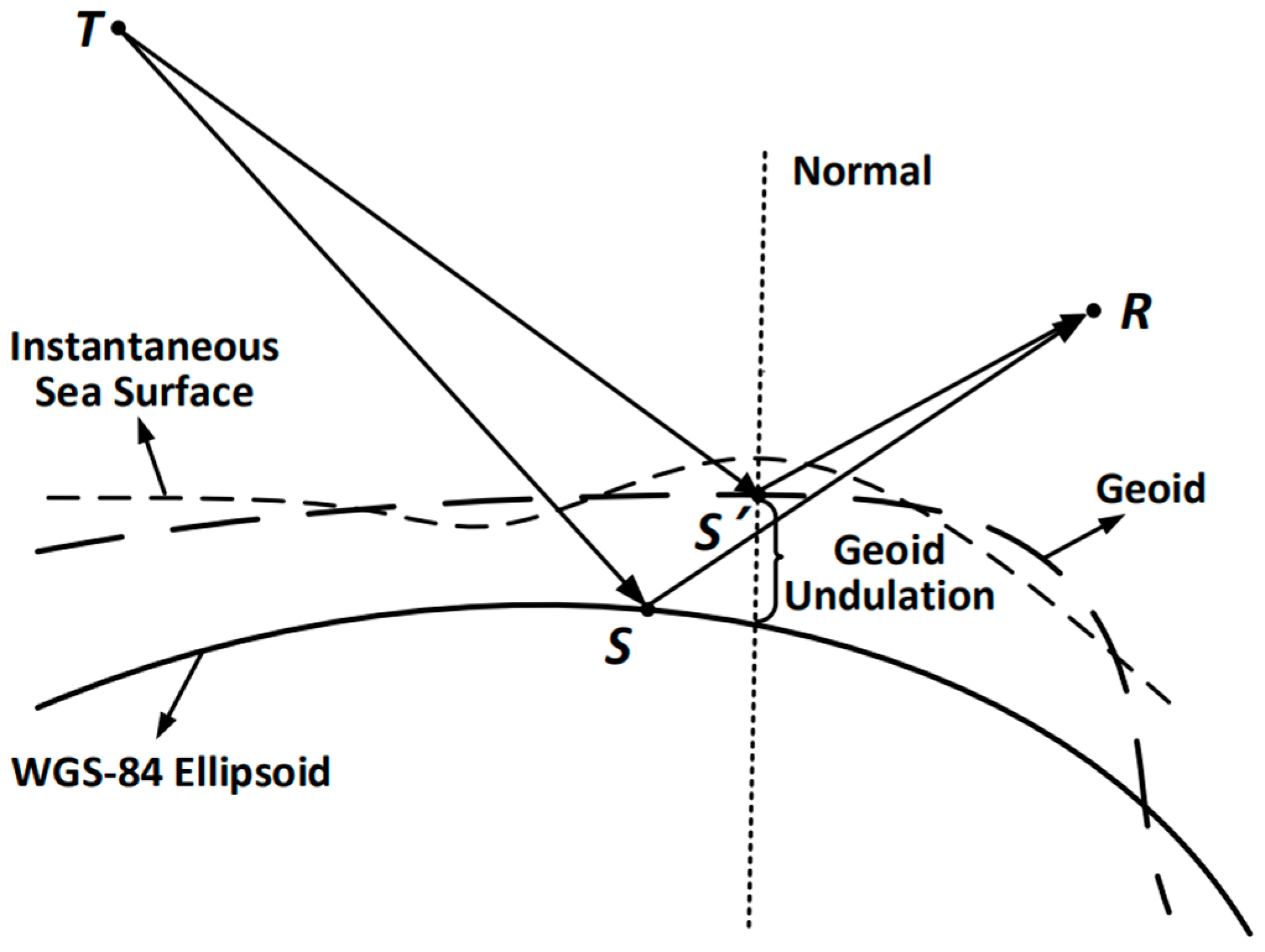
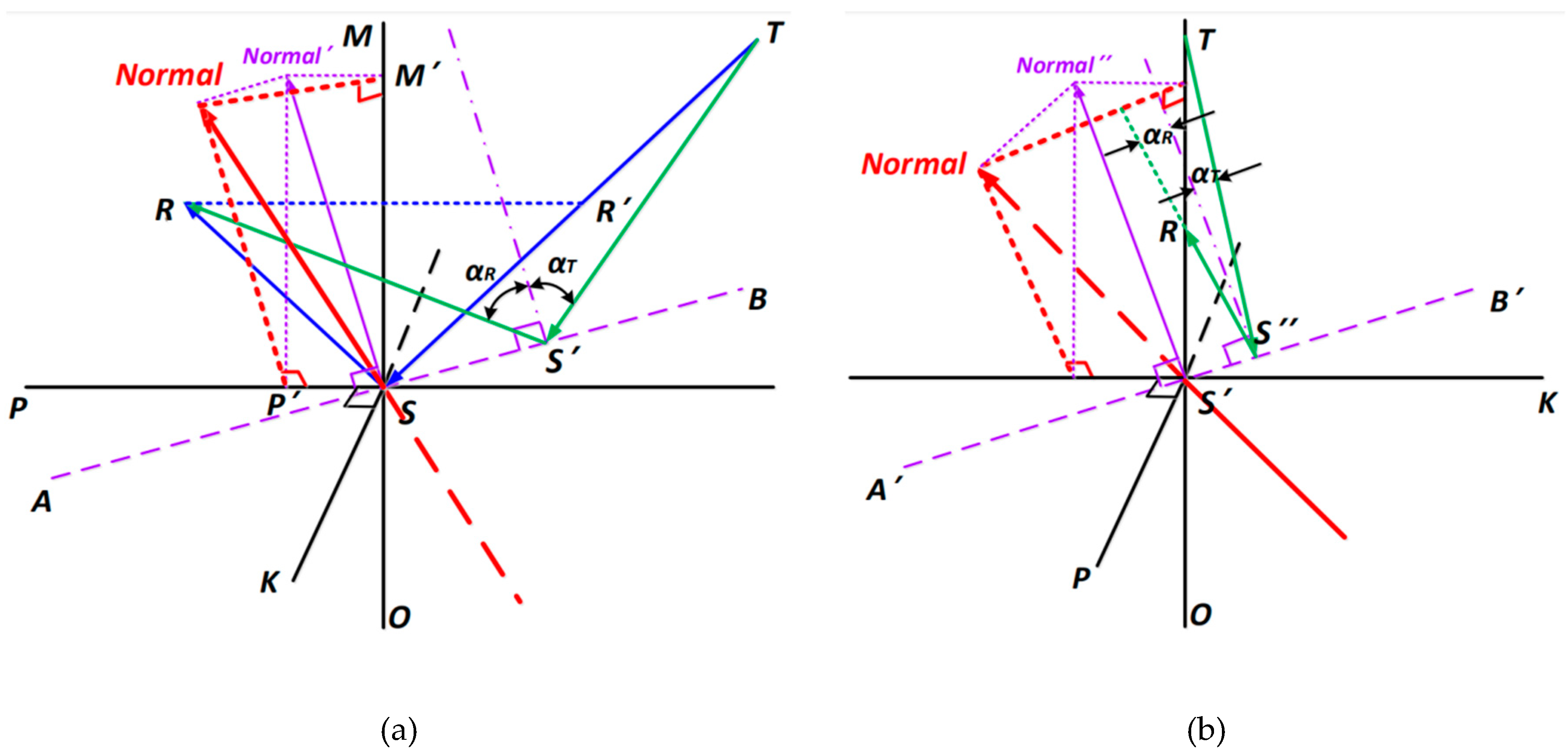
2.2.2. The Normal Projection Reflection Reference Surface Correction Method

The GFRRSCM is based on the assumption that the normal and the radial directions of the specular reflection point are identical, while actually, there is difference between them. Therefore, it is necessary to take the plane perpendicular to the normal as the reflection reference surface to correct the position by the GFRRSCM. The normal of the WGS-84 ellipsoid is taken as the normal here.
The idea of the radial–normal correction of the S-C Wu method is to calculate the correction based on a geometric relationship built by equal-quantity substitution, iterating until the correction is small, but the positioning accuracy would be affected by the approximation in the substitution [28]. In order to reduce the influence of the approximation, a normal projection correction method is proposed, which positions the specular reflection point by directly solving the spatial geometric relationship between the projection of the normal on the plane and the reflection path. The positioning error caused by the normal–radial difference can be decomposed into the incidence planes TSR and its vertical plane SOK, as shown in Figure 3, the correction is carried out in these two planes. It has been found through experiments that after the normal correction in TSR, the normal correction is usually small in SOK, therefore, the correction is first applied in TSR and then in SOK for ease of calculation. As shown in Figure 3a, the projection of the normal of S in TSR is calculated first, then the intersection AS of the normal reflection reference plane and TSR is calculated, and finally the position of the specular reflection point on the intersection line is calculated, details are as follows.
1.   The projection of the normal in TSR.
S is the projection of the normal S in TSR, it is the resultant vector of the sub-vectors S M and S P in S M and S P (i.e., R R ) directions, respectively, thus:
S = S P + S M ,
2.  The intersection of the normal reflection reference plane and TSR.
The intersection AS of the normal reflection reference plane and TSR must satisfy (1) A S is perpendicular to S ; (2) A is in TRS, thereby the direction of A S is determined.
3.  Position of S′.
The specular reflection point S′ must satisfy (1) S′ is on AS; (2): α T = α R , according to which the space coordinates of S′ can be calculated.
4.  Iteratively correcting the position of S′.
The above processes are iterated by replacing the S position with the S′ position until SS′ is less than the iteration cutoff threshold 0.01 m. The correction in SOK is similar as that in TSR above, see Figure 3b.

3. Results

3.1. The Normal Projection Reflection Reference Surface Correction Method

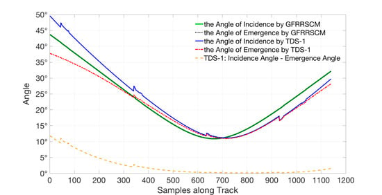
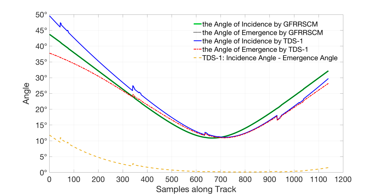
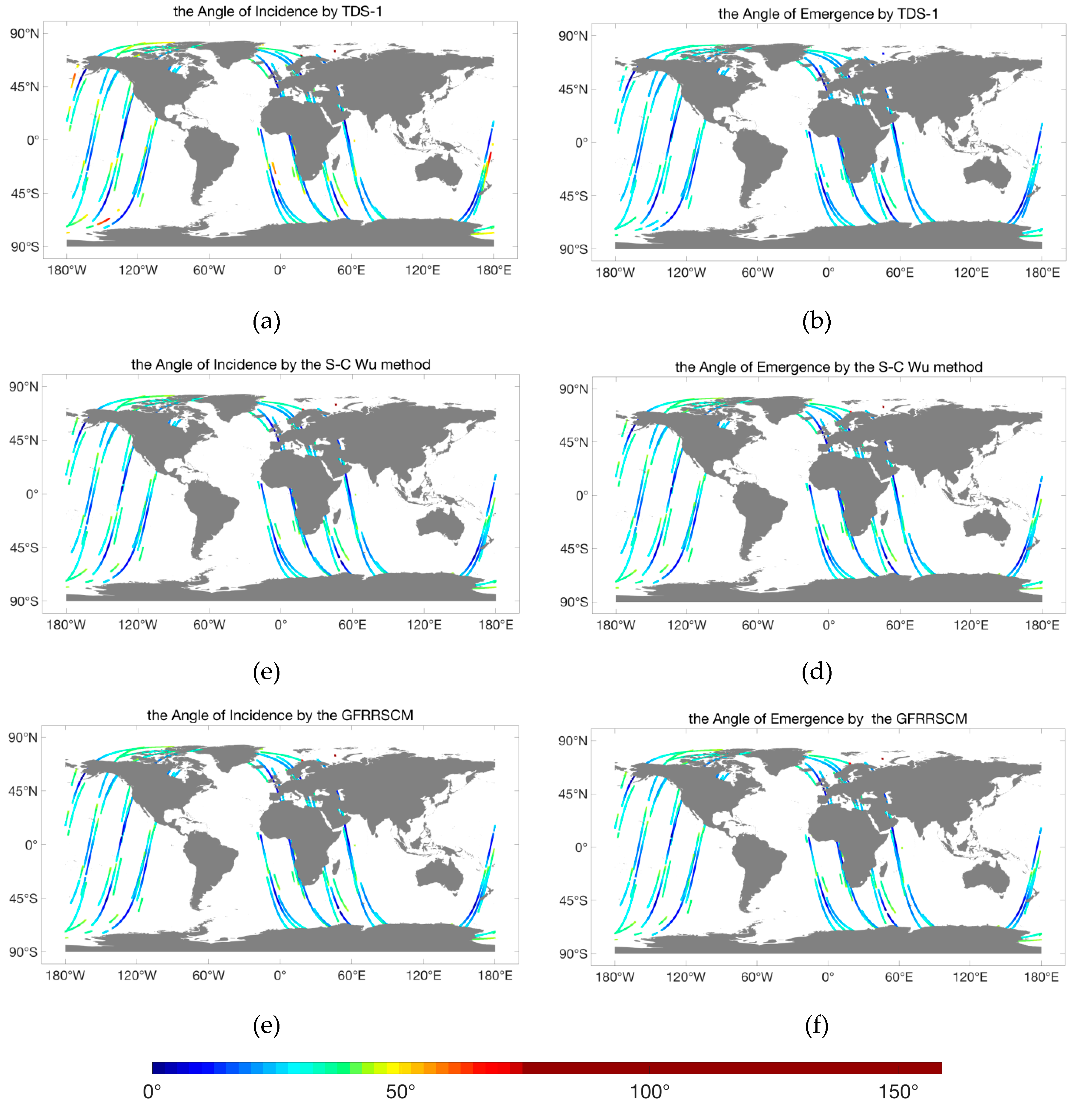
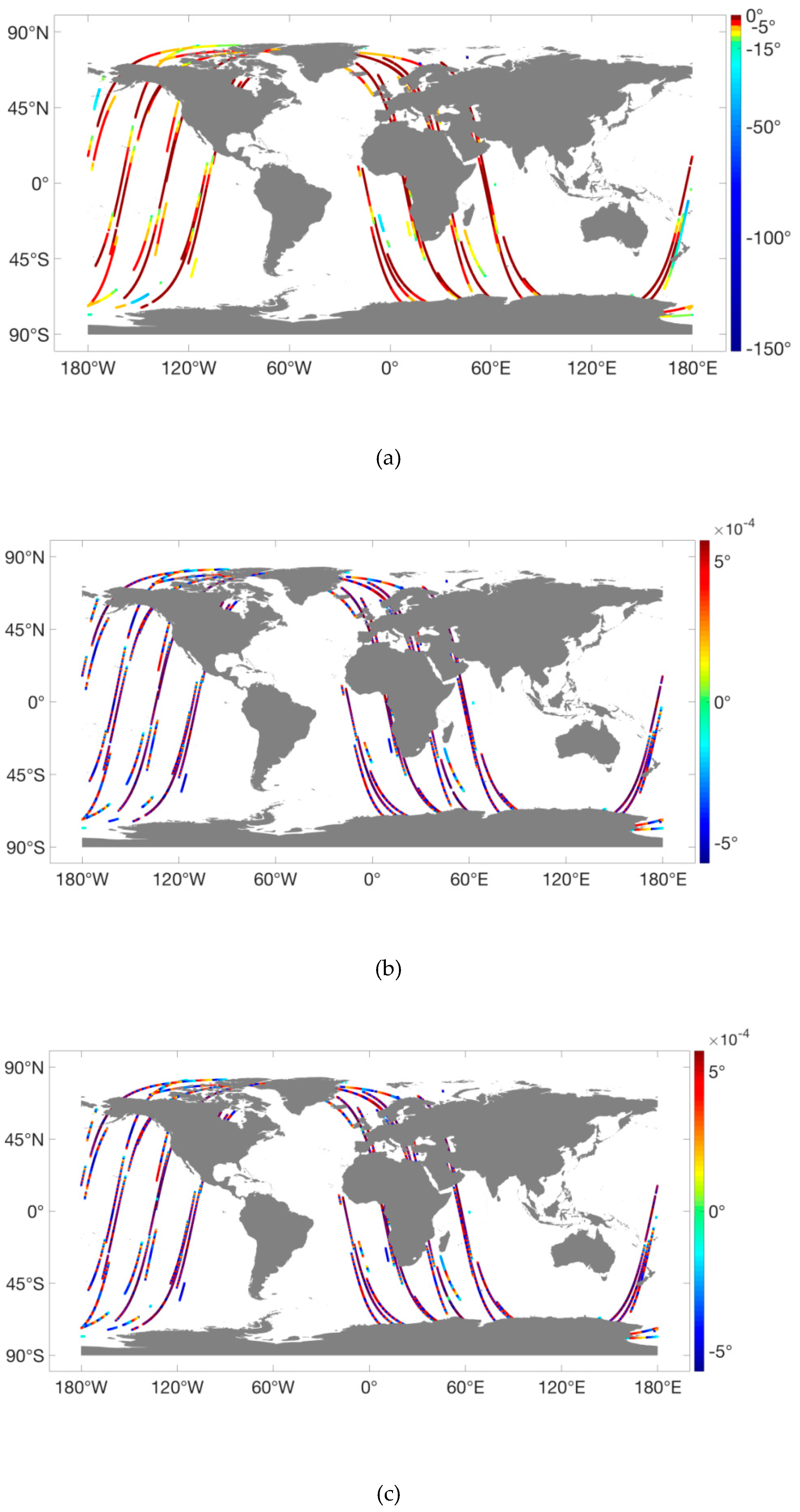
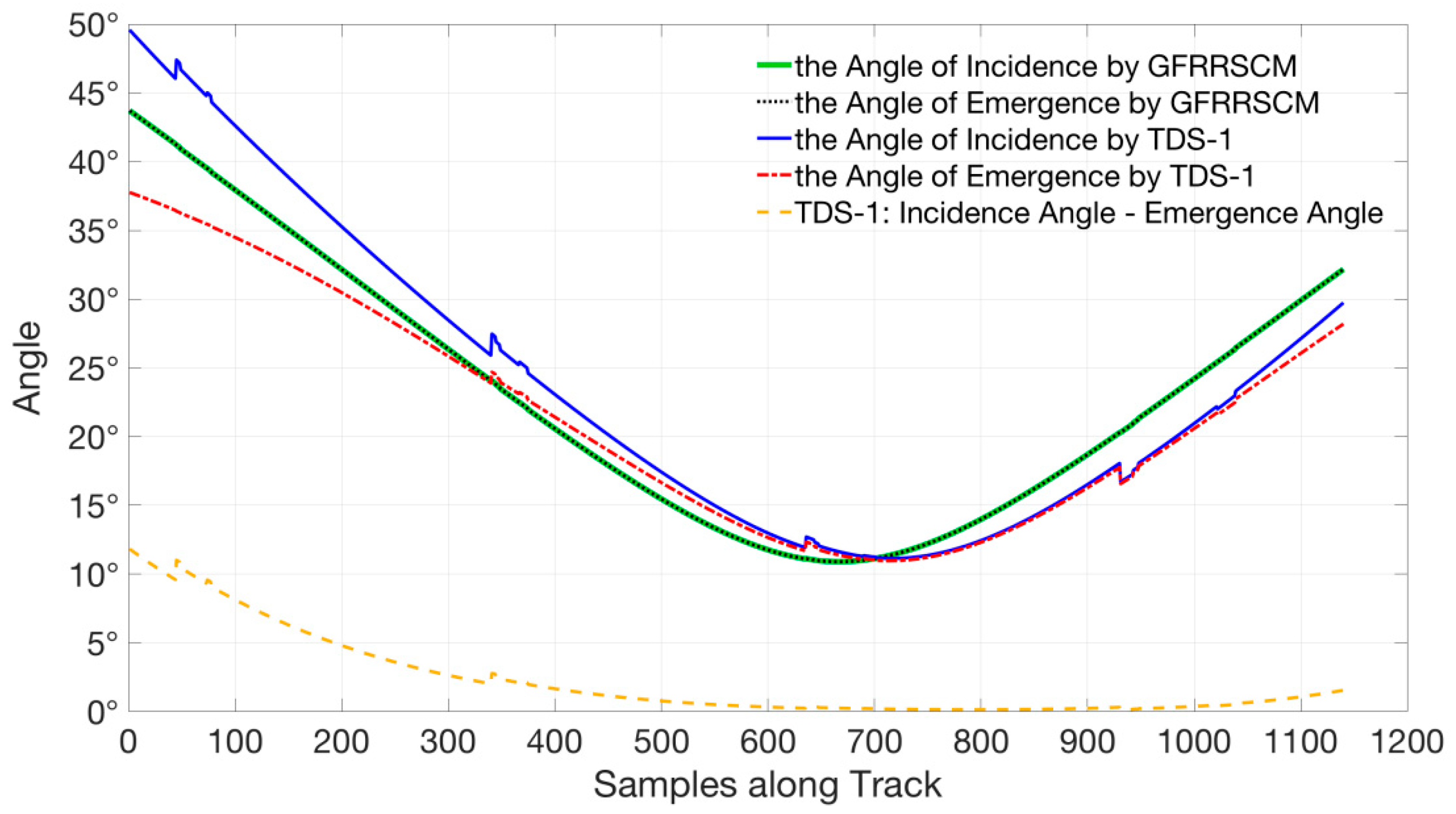
3.1.1. The Angle of Incidence and Emergence

In order to compare the accuracy of the specular reflection point position methods, the angle of incidence and emergence were calculated according to the positions of the transmitter, the receiver, and the specular reflection points contained in the TDS-1 dataset and those calculated by the S-C Wu method and the GFRRSCM. Taking the results of the 95 tracks from 21:00 31 March to 3:00 1 April 2018 (UTC) as an example, the specular reflection point positions in the geodetic coordinate system and the corresponding angles of incidence and emergence are shown in Figure 4. The TDS-1 orbited the earth for about four circles in six hours, and there was a maximum of four sub-tracks on earth’s surface at the same time in each circle, resulting from the four channels of the SGR-ReSI. The angle of incidence by TDS-1 varies the most, the variation on the same track can be up to about 50°, which is significantly higher than the other methods. With a significant difference from the angle of incidence, TDS-1 has smaller variation in the angle of emergence. Since the GFRRSCM and the S-C Wu method approach the actual position of the specular reflection point on the reflection reference surface based on iterative method, the maximum difference between the angle of incidence and emergence is less than the high-accuracy iteration cutoff threshold. There is no distinguishable difference between the angle of incidence and emergence by both the S-C Wu method and the GFRRSCM. In addition, there was no significant difference between the tracks by the S-C Wu method and those by the GFRRSCM, which means that the positioning results of the two methods are very close in the geodetic coordinate system, while the tracks by TDS-1 are different from the other two methods.
Figure 5 is the difference between the angles of emergence and incidence by the three methods in Figure 4. The TDS-1 has the largest angle difference, and the maximum reaches 150°, indicating that the specular reflection point positioning error is large. Since the same high-accuracy correction iteration cutoff threshold 10−5 rad is set, the angle difference by the S-C Wu method and that by the GFRRSCM are both small. No significant difference between the results of the two methods is observed, indicating that their reflection geometric relationships are more accurate than TDS-1’s, and the specular reflection points have higher positioning accuracy. Furthermore, it has been observed in the results of all the three methods that the angle difference on the same track is not changing continuously, there are continuous jumps along the tracks. The magnitude of the jumps are degrees in the TDS-1 results, and 10−4 degrees in the results of both the S-C Wu method and the GFRRSCM, discussions in detail are in Section 4.
In order to quantitatively analyze and compare the accuracy of the reflection geometric relationship determined by the specular reflection point positions of the three methods, the angle of incidence, emergence, and the difference between them are calculated based on the TDS-1 data of April 2018, as shown in Table 1. Because of the same iteration cut-off threshold set, the GDRRSCM and the S-C Wu method have very close angle difference, which are much smaller than that of TDS-1, indicating that the reflection geometric relationship and the corresponding specular reflection point position by the two methods are close and both of them are more accurate than those in the TDS-1 data.
The angle of incidence and emergence determined by the GFRRSCM and the S-C Wu method are equal in the effective numbers, and the standard deviation of the angle of incidence is slightly larger than that of the angle of emergence for both the two methods, indicating that the reflection geometric relationships determined by the two methods are very close. Compared with these two methods, the angle of incidence by TDS-1 is about 1.7° larger, the standard deviation is about 0.8° larger, while the angle of emergence is about 1.8° smaller, and the standard deviation is about 0.8° smaller. The angle of incidence and its variation by TDS-1 are larger, the angle of emergence and its variation are smaller than the other methods, which is consistent with the 6 h data results shown in Figure 4 and Figure 5. According to the standard deviations of the angles by all the three methods, the angles of incidence vary more than the angles of emergence by varying degrees, presumably due to the difference in satellite orbit height (GPS 20,200 km, TDS-1 635 km). The distance from the GPS satellites to the specular reflection point is much longer than that from the TDS-1 satellite to the specular reflection point, so that the specular reflection point positioning error is amplified in the incidence direction compared to the reflective direction. The GFRRSCM and the S-C Wu method both have much more stable angles of incidence and emergence along the tracks than TDS-1, these two methods apparently control the amplification effect of the specular reflection point positioning error with increasing distance better than TDS-1.

3.1.2. The Specular Reflection Point Positioning Accuracy

In order to quantify and compare the differences in the positioning accuracy of the three methods, the arithmetic mean of modes of the spatial distances (Euclidean distance) and the coordinates difference in the geodetic and the space coordinates systems with the corresponding standard deviations between the specular reflection points positions by the three methods were calculated based on April 2018 TDS-1 data, see Table 2. Based on the results in Section 3.1.1, the positioning accuracy of the S-C Wu method and the GFRRSCM is relatively close and both higher than that of TDS-1. Therefore, the positioning improvement by the S-C Wu method to TDS-1 can be regarded as that by the GFRRSCM to TDS-1, it also quite shows the positioning error caused by the elevation difference between the TDS-1 reflection reference surface and the sea surface, see the second row of Table 2. In the space coordinate system, the S-C Wu method improves the positioning accuracy by more than 40 km based on that by TDS-1. The accuracy in the Z direction is improved the most, exceeding 27 km, and the accuracy in the X and Y directions is improved by more than 17 km. In the geodetic coordinate system, the comprehensive positioning accuracy is improved by about 0.4°, the accuracy of longitude and latitude is improved by the same magnitude, while longitude is improved more.
The improvement of the positioning accuracy by the S-C Wu method to TDS-1 can be regarded as that by the GFRRSCM to TDS-1 considering the huge relative difference of positioning accuracy. Compared with the S-C Wu method, the GFRRSCM corrects the reflection reference surface from the WGS-84 ellipsoid to geoid. The difference in the specular reflection point position between the two methods shows the improvement by reducing the elevation difference between the reflection reference surface and the sea surface, it also quite shows the positioning error caused by the elevation difference between the WGS-84 ellipsoid and the sea surface, see the fourth row of Table 2. In the space coordinate system, the positioning accuracy is improved by 25.15 m. The improvement in the X, Y, and Z directions in Table 2 are the elevation correction σx, σy, and σz in Equation (2), respectively. The accuracy in the Z direction is improved the most, by about 15 m, and in the X and Y directions the accuracy is improved by about 11 m. In the geodetic coordinate system, the comprehensive positioning accuracy is improved by about 2 × 10⁻⁴°, the accuracy of latitude and longitude is improved by the same magnitude, while latitude is improved more.

3.2. The Normal Projection Reflection Reference Surface Correction Method

The Normal Projection Reflection Reference Surface Correction Method (NPRRSCM) was applied to the GPRRSCM’s specular reflection point positions of 24 h to further correct the reflection reference plane, and the positioning results were compared with those by the GFRRSCM and the S-C Wu method, respectively, as shown in Table 3. The NPRRSCM corrects the radial–normal difference of the specular reflection points positions by the GFRRSCM, and the positioning accuracy of the GFRRSCM is further improved by 13.05 m towards the normal. In all the space coordinate directions, the accuracy is improved by ~6–7 m, about 7 m in the X and Y directions, and about 6 m in the Z direction.
Compared with the position by the S-C Wu method, the position by the NPRRSCM is the result after the gravity field and the normal reflection reference plane correction in turn, that is the position by the gravity field (GF)-NPRRSCCM. The specular reflection point is corrected from the WGS-84 ellipsoid to geoid, and then the radial–normal difference is reduced, and the positioning accuracy of S-C Wu method is finally improved by 28.66 m. In the Z direction, the accuracy is improved the most, by about 16 m, and in the X and Y directions, the accuracy is improved by about 13 m.

4. Discussion

The improvements of the positioning accuracy of the specular reflection point are in accordance with the tens of meters magnitude of geoid undulation [1]. According to the corrections of the GFRRSCM and the NPPRSCM, the positioning error caused by the reflection reference surface elevation difference is about twice that caused by the normal–radial difference, indicating that the elevation difference of the reflection reference surface is the main error source of the specular reflection point positioning. In the space coordinate directions, the positioning accuracy improvement in the Z direction is the most by the GFRRSCM but the least by the NPRRSCM. As the combination result, the GF-NPRRSCCM also has the highest accuracy improvement in the Z direction consistent with the GFRRSCM; this is because the positioning correction to the elevation difference is larger than that to the normal–radial difference. The accuracy improvement in the X and Y directions are always close by both the GFRRSCM and the NPRRSCM.
In order to study the along-track variation of the reflection geometry determined by the specular reflection points by different methods, the results of the 5th track from 21:00 31 March to 3:00 1 April 2018 (UTC) are taken as an example. Figure 6 shows the angles of incidence and emergence, and the differences between them determined by the specular reflection point by the GFRRSCM and TDS-1. The angles of incidence and emergence by the two methods reduce first, and then increase. As the angles approach the minimum, the decreasing speed of the angles gradually reduces, while after reaching the minimum, the increasing speed of the angles gradually increases to a stable level subsequently. This change of the angles reflects the change in the angle between the position vectors of the TDS-1 satellite and the GPS satellites.
The angles of emergence by TDS-1 differ greatly from the angles of incidence, and their difference increases with the angle increases, indicating that the larger the angle of incidence or emergence, the larger the error of the reflection geometric relationship and the lower the accuracy of the specular reflection point positioning by TDS-1. When the angle of incidence exceeds 20°, the angle difference of TDS-1 is about 1°. When the angle of incidence exceeds 45°, the angle difference exceeds 10°. If the TDS-1 specular reflection point position data is used, the corresponding angle of incidence or emergence should be screened to select more accurate specular reflection point positions considering the related distance error. Compared with TDS-1, the angles of incidence and emergence by the GFRRSCM are very close, and their difference does not change significantly as the angle changes along the track.
In addition, the angles of incidence and emergence by TDS-1 are observed to jump along the track. This kind of jump causes the difference between the two to jump about ±2° as shown in Figure 5a. The interval of these jumps is about 300 samples, and since the sampling time interval of SGR-ReSI is 1 s, the jumps’ time interval is about 5 min. Furthermore, the positive and negative of the angle jumps are opposite before and after the angle reaching the minimum. This is presumably because the low-noise amplifier of the TDS-1 satellite receiver’s nadir load was switched from the nadir pointing antenna to the built-in blackbody to calibrate the noise reference every 5 min [36], but this calibration inevitably affects its own specular reflection point positioning accuracy. Although these jumps also affect the reflection geometry determined by the GFRRSCM, the jumps of the angle difference are on the order of 10−4°, which can be ignored.
The method proposed in this study will be an important support for the research team to improve the accuracy of underwater gravity matching navigation based on the high-accuracy and high-spatial-resolution GNSS-R altimetry constellation principle. At present, we have carried out sea surface altimetry experiments based on shipborne GNSS-R receiving instruments in different regions and weather conditions in the East China Sea and South China Sea. The method proposed in this study will be applied to the collected data to correct the position of the specular reflection point, and to study the different influences of the specular reflection points positioning accuracy improvement on the altimetry accuracy in regions with different geoid undulations and sea surface conditions. On the other hand, this study introduces the correction of the main factor which determines the sea surface elevation—the earth’s gravity field—and corrects the reflection reference surface to geoid. On this basis, the subsequent work will introduce the ocean tidal model to further correct the reflection reference surface, in order to further improve the positioning accuracy of the specular reflection point, and to finally establish a global and full-sea-state reflection reference surface model. Additionally, the TDS-1 satellite data only contains GPS reflection data. With the completion and full operation of the four major GNSSs and the publications of their precise orbit information in the future, we will introduce the data of more GNSSs. This will help us to study the difference in positioning accuracy of specular reflection points between different GNSSs due to their different parameters such as orbit and signal, etc., and the corresponding different effects on sea surface altimetry accuracy.

5. Conclusions

The positioning error of the specular reflection point is the main error source reducing the accuracy of GNSS-R sea surface altimetry, and reflection reference surface correction is the key to improving the positioning accuracy. Integrating a variety of ocean dynamic parameters to establish a global all-sea-state reflection reference surface model is not only an important task to improve the accuracy of GNSS-R sea surface altimetry, but also a precondition for exerting GNSS-R’s high-spatial-resolution observation advantage and realizing its application value. As an important factor determining the sea surface elevation, the earth’s gravity field plays a significant role in constructing the all-sea-state reflection reference surface model.
In this study, based on the correction of the GNSS-R reflection reference surface to geoid, a gravity field normal projection reflection reference surface combination correction method is proposed to improve the positioning accuracy of the specular reflection point. Firstly, the position of the specular reflection point was preliminarily calculated with the WGS-84 ellipsoid as the reflection reference surface using the receiver and the transmitter positions contained in the dataset of SGR-ReSI carried by the TDS-1 satellite. Secondly, the elevation correction calculated based on the earth’s gravity field model EGM2008 was introduced in the positioning iteration to correct the reflection reference surface to geoid, which is much closer to the sea surface than the WGS-84 ellipsoid surface. This step reduces the specular reflection point positioning error caused by the elevation difference between the reflection reference surface and the sea surface. Finally, based on the GFRRSCM, the normal projection reflection reference surface correction method corrected the normal–radial difference, and reduced the influence of the approximate substitution on the calculation accuracy by directly solving the spatial geometry related to the normal reflection reference plane.
Applying the GF-NPRRSCCM proposed in this study, the positioning accuracy of the GPS-R specular reflection point with the WGS-84 ellipsoid as the reflection reference surface was improved by 28.66 m. Specifically, the GFRRSCM improved the positioning accuracy by 25.15 m, based on which the NPRRSCM further improved the positioning accuracy by 13.05 m towards the normal. The elevation difference between the reflection reference surface and the sea surface was the main error source of the specular reflection point positioning relative to the normal–radial difference. Based on the quantitative evaluation and comparison of the reflection geometry accuracy, the GFRRSCM was more accurate than the TDS-1 positioning, which was improved by more than 40 km by the GFRRSCM. The amplification of the positioning error related to the satellite orbit height was much better controlled by the GFRRSCM. The reflection geometric relationship error of TDS-1 data increases with the the angle of incidence increases. When the angle of incidence exceeds 20°, the specular reflection point position data should be used with caution for accuracy concerns, while the GFRRSCM does not have this problem. The TDS-1 SGR-ReSI black-body calibration on the noise reference results in error of its own specular reflection point positioning, but no obvious impact of this calibration is observed in the geometric relationship determined by the GFRRSCM positioning result.

Author Contributions

F.W. and W.Z. conceived the experiments and wrote the paper; F.W. designed and performed the experiments; Z.Li provided theory support for the index requirement of GNSS-R sea surface altimetry; Z.Liu provided suggestions for the experiments and the analysis of the results.

Funding

This work was supported by the National Nature Science Foundation of China (41574014, 41774014), the Frontier Science and Technology Innovation Project (085015) and the Innovation Workstation Project of the Science and Technology Commission of the Central Military Commission, and the Outstanding Youth Fundation of the China Academy of Space Technology.

Acknowledgments

The TDS-1 SGR-RESI dataset used in this study is supported by the MERRByS team of Surrey Satellite Technology Limited.

Conflicts of Interest

The authors declare no conflict of interest.

References

  1. Yang, D.; Zhang, Q. GNSS Reflected Signal Processing: Fundamentals and Applications; Publishing House of Electronics Industry: Beijing, China, 2012. [Google Scholar]
  2. Martin-Neira, M. A Passive Reflectometry and Interferometry System (PARIS): Application to ocean altimetry. ESA J. 1993, 17, 331–355. [Google Scholar]
  3. Auber, J.C.; Bilbaut, A.; Rigal, J.M. Characterization of Multipath on Land and Sea at GPS Frequencies. In Proceedings of the 7th International Technical Meeting of the Satellite Division of the Institute of Navigation (ION GPS 1994), Salt Lake City, UT, USA, 20–23 September 1994; pp. 1155–1171. [Google Scholar]
  4. Katzberg, S.J.; Garrison, J.L. Utilizing GPS to Determine Ionospheric Delay over the Ocean; NASA Technical Memorandum; NASA Langley Technical Report Server: Hampton, VA, USA, 1996; p. 4750.
  5. Garrison, J.L.; Katzberg, S.J.; Hill, M.L. Effect of sea roughness on bistatically scattered range coded signal from the global positioning system. J. Geophys. Res. Lett. 1998, 25, 2257–2260. [Google Scholar] [CrossRef]
  6. Lowe, S.T.; Hajj, G.L. Detection of an ocean-Reflected GPS signal. In Proceedings of the GPS Surface Reflection Workshop at Goddard Space Flight Center, Pasadena, CA, USA, 20–21 July 1998. [Google Scholar]
  7. Zavorotny, V.U.; Voronovich, A.G. Scattering of GPS signals from the ocean with wind remote sensing application. J. IEEE Trans. Geosci. Remote Sens. 2000, 38, 951–964. [Google Scholar] [CrossRef]
  8. Martin-Neira, M.; Caparrini, M.; Font-Rossello, J.; Lannelongue, S.; Vallmitjana, C.S. The PARIS concept: An experimental demonstration of sea surface altimetry using GPS reflected signals. J. IEEE Trans. Geosci. Remote Sens. 2001, 39, 142–150. [Google Scholar] [CrossRef]
  9. Martin-Neria, M.; Colmenarejo, P.; Runi, G.; Serra, C. Ocean altimetry using the carrier phase of GNSS reflected signals. Cersat J. 2000, 11, 22. [Google Scholar]
  10. Rivas, M.; Martin-Neira, M. Coherent GPS Reflections from the Sea Surface. J. IEEE Geosci. Remote Sens. Lett. 2006, 3, 28–31. [Google Scholar]
  11. Lowe, S.T.; Zuffada, C.; Chao, Y.; Kroger, P.; Young, L.E.; LaBrecque, J.L. 5-cm precision aircraft ocean altimetry using GPS reflections. J. IEEE Geophys. Res. Lett. 2002, 29, 1375. [Google Scholar] [CrossRef]
  12. Ruffini, G.; Soulat, F.; Caparrini, M.; Germain, O.; Martín-Neira, M. The Eddy experiment: Accurate GNSS-R ocean altimetry from low altitude aircraft. J. Geophys. Res. Lett. 2004, 31. [Google Scholar] [CrossRef]
  13. Hajj, G.A.; Zuffada, C. Theoretical Description of a Bistatic System for Ocean Altimetry Using the GPS Signals. J. Ratio Sci. 2003, 38, 10. [Google Scholar] [CrossRef]
  14. Lowe, S.T.; LaBrecque, J.L.; Zuffada, C.; Romans, L.J.; Young, L.E.; Hajj, G.A. First spaceborne observation of an Earthreflected GPS signal. J. Radio Sci. 2002, 37, 1–28. [Google Scholar]
  15. Beyerle, G.; Hocke, K. Observation and Simulation of Direct and Reflected GPS Signals in Radio Occultation Experiment. J. Geophys. Res. Lett. 2001, 28, 1895–1898. [Google Scholar] [CrossRef]
  16. Beyerle, G.; Hocke, K.; Wickert, J.; Schmidt, T.; Marquardt, C.; Reigber, C. GPS Radio Occultations with CHAMP: A Radio Holographic Analysis of GPS Signal Propagation in the Troposphere and Surface Reflections. J. Geophys. Res. 2002, 107, 27. [Google Scholar] [CrossRef]
  17. Gleason, S.; Hodgart, S.; Sun, Y.; Gommenginger, C.; Mackin, S.; Adjrad, M.; Unwin, M. Detection and processing of bistatically reflected GPS signals from low Earth orbit for the purpose of ocean remote sensing. J. IEEE Trans. Geosci. Remote Sens. 2005, 43, 1229–1241. [Google Scholar] [CrossRef]
  18. Foti, G.; Gommenginger, C.; Jales, P.; Unwin, M.; Shaw, A.; Robertson, C.; Rosello, J. Spaceborne GNSS reflectometry for ocean winds: First results from the UK TechDemoSat-1 mission. J. Geophys. Res. Lett. 2015, 42, 5435–5441. [Google Scholar] [CrossRef] [Green Version]
  19. Clarizia, M.P.; Ruf, C.; Cipollini, P.; Zuffada, C. First spaceborne observation of sea surface height using GPS–Reflectometry. J. Geophys. Res. Lett. 2016, 43, 767–774. [Google Scholar] [CrossRef]
  20. Ruf, C.; Gleason, S.; Jelenak, Z.; Katzberg, S.; Ridley, A.; Rose, R.; Scherrer, J.; Zavorotny, V. The NASA EV-2 cyclone global navigation satellite system (CYGNSS) mission. In Proceedings of the IEEE Aerospace Conference, Big Sky, MT, USA, 2–9 March 2013; pp. 1–7. [Google Scholar]
  21. Ruf, C.; Lyons, A.; Unwin, M.; Dickinson, J.; Rose, R.; Rose, D.; Vincent, M. CYGNSS: Enabling the future of hurricane prediction [remote sensing satellites]. J. IEEE Geosci. Remote Sens. Mag. 2013, 1, 52–67. [Google Scholar] [CrossRef]
  22. Yan, L.; Cui, C.; Wu, H. A gravity matching algorithm based on TERCOM. J. Geomat. Inf. Sci. Wuhan Univ. 2009, 34, 261–264. [Google Scholar]
  23. Tong, Y.; Bian, S.; Jiang, D. A new intergrated gravity matching algorithm based on approximated local gravity map. J. Geophys. 2012, 55, 2917–2925. [Google Scholar]
  24. Dixon, T.; Rodriguez, E.; Martin, J.; Tralli, D. Section 2.1: High Resolution Continental Topographic Data: Scientific Applications and a Possible Approach. In Proceedings of the Consultative Meeting on Imaging Altimeter Requirements and Techniques, Mullard Space Science Lab, Dorking, UK, 30 May–1 June 1990. [Google Scholar]
  25. Alenia. Final Report for the Constellation of Pulse Limited Nadir Looking Radar Altimeters; IAB/FR/ALS/001, ESTEC Contract 9370/91; ESTEC: Noordwijk, The Netherlands, 1992. [Google Scholar]
  26. Zheng, W.; Xu, H.; Zhong, M.; Yuan, M.; Zhou, X.; Peng, B. Efficient and rapid estimation of the accuracy of future GRACE Follow-On Earth’s gravitational field using the analytic method. J. Geophys. 2010, 53, 796–806. [Google Scholar] [CrossRef]
  27. Helm, A. Ground-Based GPS Altimetry with the L1 OpenGPS Receiver Using Carrier Phase-Delay Observations of Reflected GPS Signals. Ph.D. Thesis, Postdam Deutsches GFZ, Potsdam, Germany, 2008. [Google Scholar]
  28. Wu, S.-C.; Meechan, T.; Young, L. The potential Use of GPS Signals as Ocean Altimetry Observation. In Proceedings of the National Technical Meeting, Santa Monica, CA, USA, 14–16 January 1997. [Google Scholar]
  29. Kostelecky, J.; Klokocnik, J.; Wagner, C.A. Geometry and acuracy of reflecting points in bistatic satelite altimetry. J. Geod. 2005, 79, 421–430. [Google Scholar] [CrossRef]
  30. Rius, A.; Cardellach, E.; Martin-Neira, M. Altimetric Analysis of the Sea-Surface GPS-Reflected Signals. IEEE Trans. Geosci. Remote Sens. 2010, 48, 2119–2127. [Google Scholar] [CrossRef]
  31. Skolnik, M. Radar Handbook; McGraw-Hill, Inc.: New York, NY, USA, 1990. [Google Scholar]
  32. Gao, F.; Xu, T.; Wang, N.; Jiang, C.; Du, Y.; Nie, W.; Xu, G. Spatiotemporal Evaluation of GNSS-R Based on Future Fully Operational Global Multi-GNSS and Eight-LEO Constellations. Remote Sens. 2018, 10, 67. [Google Scholar] [CrossRef]
  33. Zhang, B.; Wang, F.; Yang, D. The algorithm for the determination of the GNSS-R specular point based on the dichotomy of the line segment. J. GNSS World China 2013, 38, 11–16. [Google Scholar]
  34. Wagner, C.; Klokocnok, J. The value of ocean reflections of GPS signals to enhance satelite altimetry: Data distribution and error analysis. J. Geod. 2003, 77, 128–138. [Google Scholar] [CrossRef]
  35. Gleason, S.; Gebre-Egziabher, D. GNSS Applications and Methods; Artech House: Norwood, MA, USA, 2009; pp. 53–71. [Google Scholar]
  36. Jales, P.; Unwin, M. MERRByS Product Manual—GNSS Reflectometry on TDS-1 with the SGR-ReSI; Surrey Satellite Technology LTD: Guildford, UK, 2017. [Google Scholar]
  37. Pavlis, N.K.; Saleh, J. Error propagation with geographic specificity for very high degree geopotential models. In Gravity, Geoid and Space Missions; Jekeli, C., Bastos, L., Fernandes, J., Eds.; Springer: Berlin, Germany, 2005; Volume 129. [Google Scholar]
  38. Pavlis, N.K.; Holmes, S.A.; Kenyon, S.C.; Factor, J.K. The development and evaluation of the Earth Gravitational Model 2008 (EGM2008). J. Geophys. Res. Solid Earth 2012, 117. [Google Scholar] [CrossRef] [Green Version]
Figure 1. The Global Navigation Satellite System Reflectometry (GNSS-R) reflection reference surface and the specular reflection point, where T is the transmitter, R is the receiver, S is the specular reflection point with the WGS-84 ellipsoid as the reflection reference surface, and S′ is the specular reflection point with geoid as the reflection reference surface.
Remotesensing 11 00033 g001
Figure 2. The GNSS-R specular reflection point positioning geometry.
Remotesensing 11 00033 g002
Figure 3. Geometry of the normal reflection reference surface correction: (a) the correction in the incidence plane, and (b) the correction in the plane perpendicular to the incidence plane.
Remotesensing 11 00033 g003
Figure 4. The angles of incidence and emergence corresponding to the specular reflection points: (a) the angles of incidence by TDS-1, (b) the angles of emergence by TDS-1, (c) the angles of incidence by the S-C Wu method, (d) the angles of emergence by the S-C Wu method, (e) the angles of incidence by the Gravity Field Reflection Reference Surface Correction Method (GFRRSCM), and (f) the angles of emergence by the GFRRSCM from 21:00 31 March to 3:00 1 April 2018 (UTC).
Remotesensing 11 00033 g004
Figure 5. The difference between the angles of emergence and incidence from 21:00 31 March to 3:00 1 April 2018 (UTC), (a) TDS-1, (b) the S-C Wu method, (c) the GFRRSCM.
Remotesensing 11 00033 g005
Figure 6. The angle of incidence and emergence and their difference on single track.
Remotesensing 11 00033 g006
Table 1. The angles of incidence and emergence with the difference between them (the angle of emergence − the angle of incidence).
TDS-1S-C Wu MethodGFRRSCM
Angleincidenceemergencedifferenceincidenceemergencedifferenceincidenceemergencedifference
Mean (°)2.822 × 1012.469 × 101−3.515 × 1002.653 × 1012.653 × 101−5.932 × 10-72.653 × 1012.653 × 101−5.932 × 10⁻⁷
Standard Deviation (°)5.618 × 1004.005 × 1001.834 × 1004.781557 × 1004.781573 × 1003.978 × 10-44.781557 × 1004.781573 × 1003.978 × 10-4
Table 2. The spatial distances and the coordinates difference modes with the corresponding standard deviations between the specular reflection points positions by the three methods.
Spatial Distance (m)X (m)Y (m)Z (m)B (°)L (°)
the S-C Wu method vs TDS-1mean4.147 × 1041.761 × 1041.736 × 1042.764 × 1043.488 × 10-14.839 × 10⁻¹
Standard deviation2.027 × 1049.304 × 1039.388 × 1031.372 × 1041.745 × 10-11.635 × 100
the GFRRSCMvs the S-CWu methodmean2.515 × 1011.085 × 1011.170 × 1011.459 × 1012.817 × 10-41.733 × 10⁻⁴
Standard deviation7.821 × 1004.352 × 1004.695 × 1006.267 × 1002.078 × 10-37.448 × 10⁻⁴
Table 3. The specular reflection point positioning accuracy improvement by the NPRRSCM and the GF-NPRRSCCM.
Spatial Distance (m)X (m)Y (m)Z (m)
MinMaxMeanMinMaxMeanMinMaxMeanMinMaxMean
the NPRRSCMto the GFRRSCM5.173 × 10-55.610 × 1011.305 × 1017.291 × 10-64.344 × 1016.843 × 1001.506 × 10-54.802 × 1016.794 × 1003.133 × 10-54.035 × 1015.832 × 100
the GF-NPRRSCCM to the S-C Wu3.958 × 10-21.045 × 1022.866 × 1013.051 × 10-58.175 × 1011.373 × 1012.884 × 10-67.657 × 1011.322 × 1013.583 × 10-58.452 × 1011.608 × 101

