1. Introduction
The reduction of greenhouse gas emissions is a fundamental goal to be achieved in the next few years. It has been estimated that CCS (carbon capture and storage) technological solutions can make a great contribution (20% emission reduction by 2020) [
1]. CCS technologies allow one to separate the carbon dioxide emitted by fossil fuel-powered plants and permanently neutralize it by removing it from exhaust released into the atmosphere. In the present day, many technological solutions proposed for CO
2 capture are available, but they have high costs in terms of energy consumption and, consequently, higher fossil fuel use and higher economic costs.
In this regard, fuel cells, after being studied as energy production devices in the hydrogen economy [
2,
3,
4,
5,
6,
7,
8,
9], have been proposed for CO
2 capture applications. In the literature, there are several works in which fuel cells have been investigated for separating CO
2 from the exhaust gas of fossil fired power plants. Operating parameters have been collected and process efficiency has been evaluated, showing that the process is technologically viable [
10,
11,
12].
In this paper, energy evaluations about a new innovative configuration for CO2 capture/separation based on MCFCs (molten carbonate fuel cells) are presented in order to compare this solution with other existing CO2 capture technologies (chemical absorption, physical absorption, physical adsorption, membrane separation processes, cryogenic separation).
The aim of this study is the analysis in terms of energy consumption per mass unit of captured CO2 made by integrating peculiar cylindrical geometry, small-sized MCFC prototypes with a gas turbine plant. Results are compared with the existing solutions described in the state-of-the-art CCS.
2. State of the Art of CCS Technological Solutions
CCS technological solutions are mainly divided into three categories:
- (1)
Post combustion: separation of CO2 from combustion products (nitrogen, oxygen, water). Capture can occur anywhere along the product processing stream, from combustor to effluent exhaust stage.
- (2)
Oxy-fuel combustion: separation of oxygen from nitrogen in the air to produce a nitrogen-free oxidizer stream. Reaction with fuel produces a stream composed primarily of CO2, oxygen and water. Water can be removed by phase separation.
- (3)
Pre-combustion: separation of carbon in the form of CO2 from a resource after the energy content of the resource is transferred to a carbon-free energy carrier. The most common configuration involves gasification with air or oxygen. The products undergo a water-gas shift to a high-concentration stream of CO2 and H2. CO2 is captured and H2 reacts with air.
The mainly used physical and chemical processes are the followings:
- –
Chemical solvent absorption (e.g., amine-based);
- –
Physical absorption/adsorption;
- –
Membrane separation processes;
- –
Phase separation (e.g., cryogenic-clathrate hydrates).
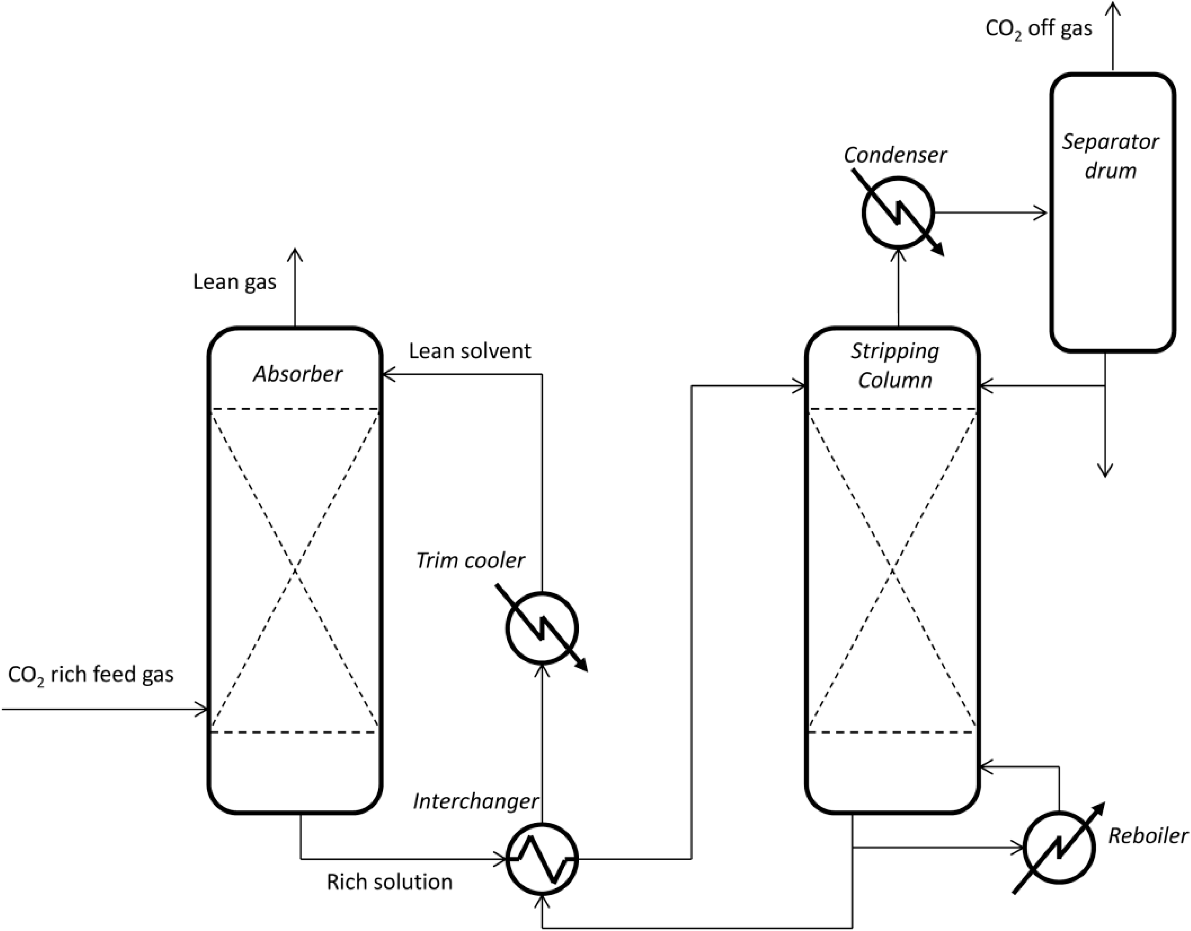
In the chemical solvents absorption process (e.g., amine-based), CO2 in the gas phase dissolves into a solution of water and amine compounds. Amines react with CO2 in solution to form protonated amine (AH+), bicarbonate (HCO3−) and carbamate (ACO2−).
When the solution has reached the intended CO
2 load, it is removed from the contact with the gas stream and heated to reverse the chemical reaction: thus, it releases high-purity CO
2 for geological storage. The process is shown in
Figure 1.
In the physical absorption/adsorption process, absorbents allow the gas to permeate a solid or liquid under one set of conditions and to desorb under others [
13,
14,
15,
16,
17]. The rate of absorption or desorption is temperature and pressure dependent. Smaller differences in conditions require less energy, but require more absorbent to capture CO
2 at an equivalent rate. The process is shown in
Figure 2.
Figure 1.
Chemical solvents absorption process plant scheme [
13].
Figure 1.
Chemical solvents absorption process plant scheme [
13].
In the membrane separation process, membrane systems include thin barriers that allow selective permeation of certain gases; thus, one component in a gas stream can pass through faster than the others [
13,
14,
17,
18].
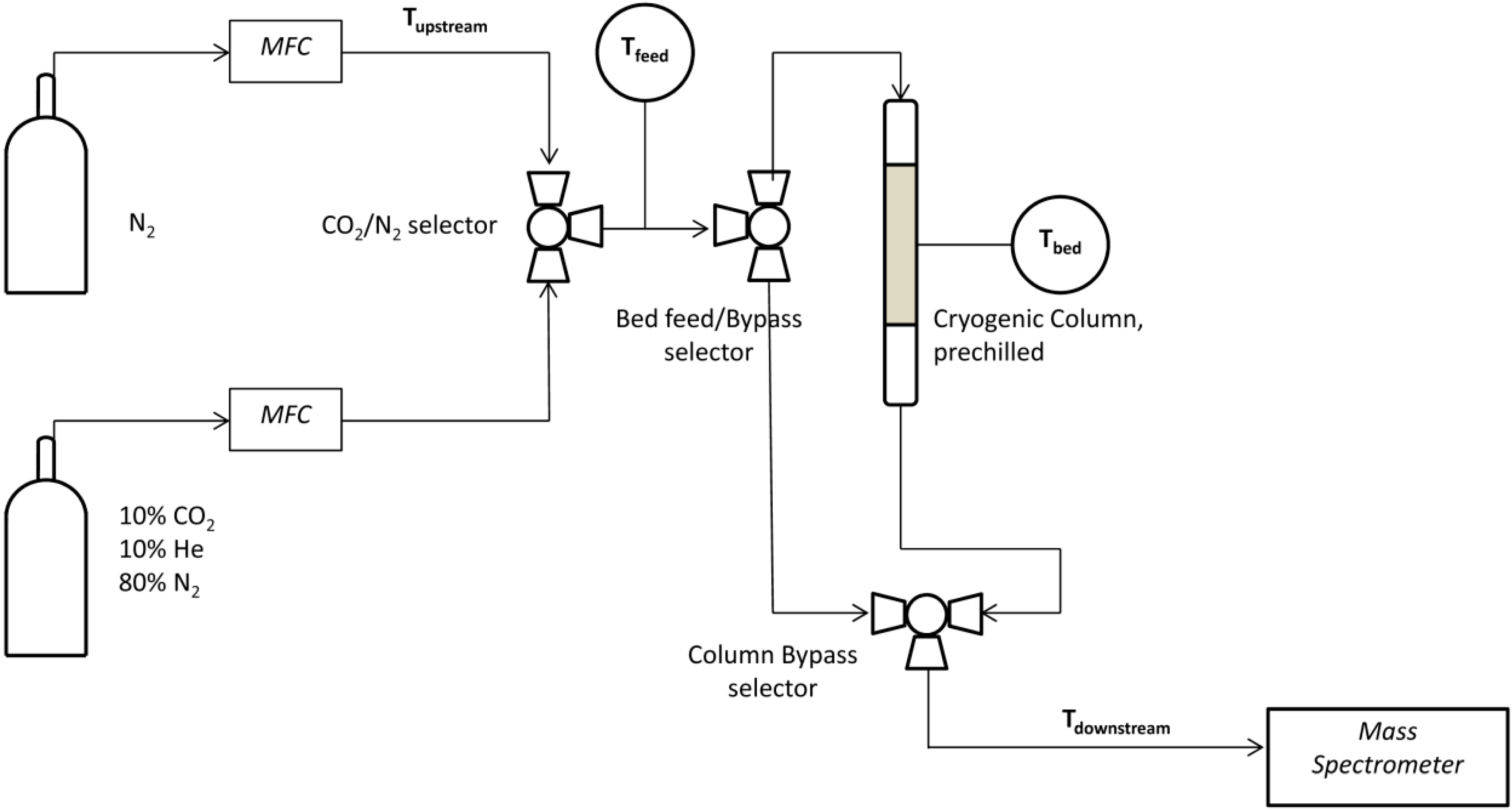
The phase separation (e.g., cryogenic-clathrate hydrates) process is based on this principle: below certain temperatures, gas molecules are moving slow enough to succumb to weak intermolecular forces [
13,
14,
19,
20]. Depending on the partial pressure of other gases in a mixture, condensing gases will form a distinct phase with a composition different from that of the vapor, which is easily separated. The process is shown in the following plant scheme (
Figure 3).
Figure 2.
Physical absorption/adsorption process plant scheme [
16].
Figure 2.
Physical absorption/adsorption process plant scheme [
16].
Figure 3.
Phase separation process plant scheme [
13].
Figure 3.
Phase separation process plant scheme [
13].
3. The Proposed Innovative CO2 Capture Solution by MCFC
3.1. The MCFC Technology
Fuel cells allow one to convert the chemical energy of a fuel (typically hydrogen) by an oxidant gas (oxygen or air), obtaining a continuous electric current, water and heat [
9]. An MCFC fuel cell essentially consists of three elements: two electrodes, cathode and anode, and a matrix that constitutes or contains the electrolyte. Fuel and oxidant gases are directed, respectively, to the anode and the cathode (on the faces opposite to those in contact with the electrolyte), feeding the oxidation reactions of the fuel and oxidizing gas reduction. Molten carbonate fuel cells (MCFCs) employ as raw material hydrocarbons (from which hydrogen fuel is obtained through a reforming reaction) and oxygen (as the oxidant). The electrolyte consists of a mixture of carbonates (typically lithium and potassium); the two electrodes are both nickel-based: the lithiated nickel oxide cathode and the anode nickel with a small percentages of chromium; the average working temperature is high, about 600–700 °C. An original cylindrical MCFC was built and investigated in the last few years at CIRIAF—University of Perugia Labs [
2,
3,
4,
5,
6]. Many facilities were tested, attaining good results. The cylindrical MCFC’s main peculiarity is the innovative stack design involving cylindrical compact geometry and original gases arrangements. The main technology benefits are: high electrical efficiency (up to 40%), thermal self-sustain conditions kept down to the kW-size stack, because of minimum heat losses due to the cylindrical geometry and gas recirculation, non-pressurized devices, long life (the proposed MCFC worked for 4,500 working hours), compact design, modularity, thanks to internal manifolds, and low external temperature. These characteristics make the cylindrical MCFC technology suitable also for the proposed CO
2 capture plant.
3.2. Plant Scheme and Chemical Process
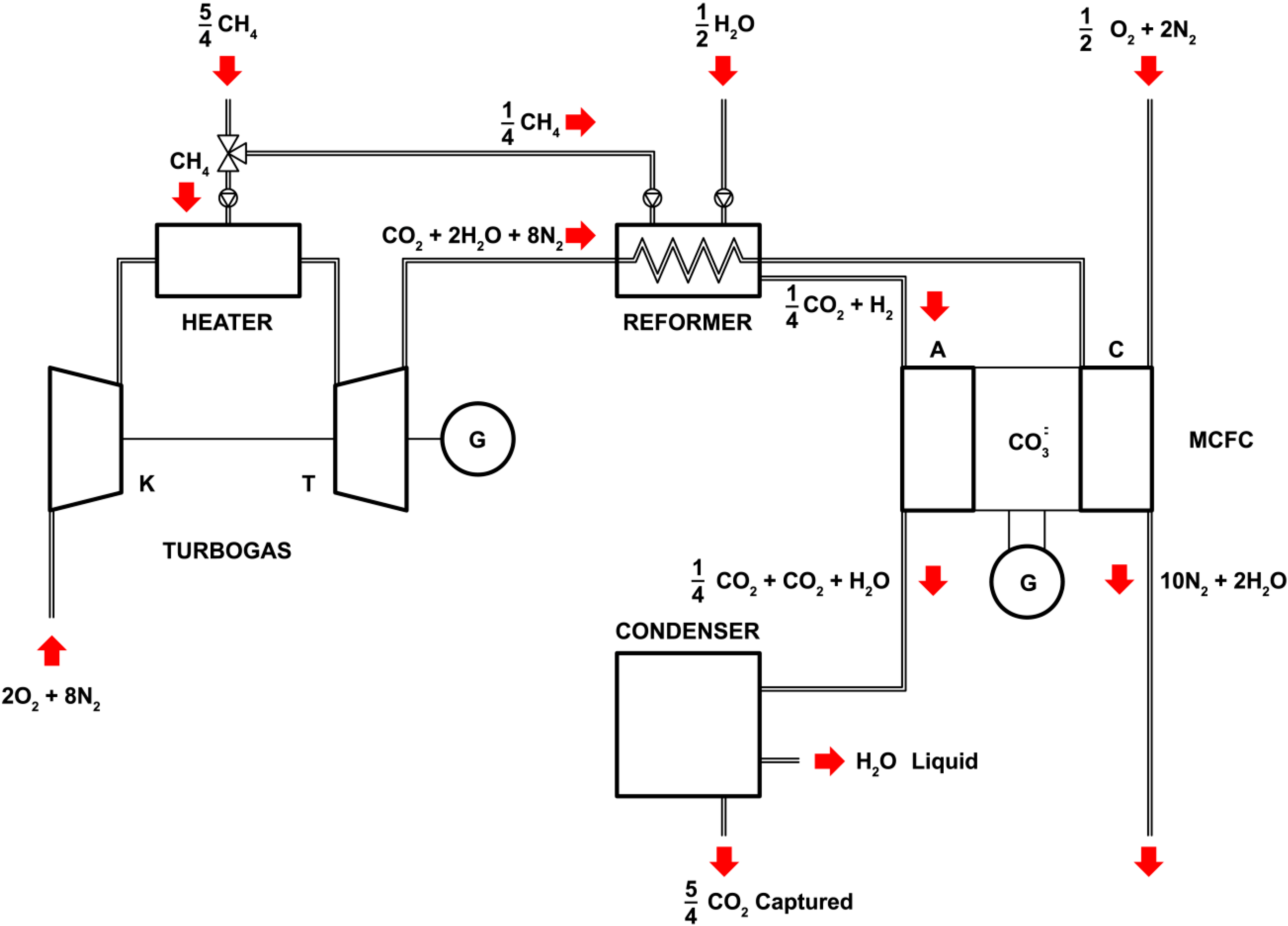
The proposed CO
2 capture chemical process by molten carbonate fuel cells is shown in
Figure 4. The CO
2 capture chemical process is analyzed when integrated with a gas turbine plant. The turbine plant is based on an open Brayton cycle. Ambient air (2O
2 + 8N
2) is drawn into a compressor (K), where it is pressurized (adiabatic process). The compressed air runs through a combustion chamber (heater) where fuel (CH
4) is burned heating the air (isobaric process). The heated pressurized air gives up its energy, expanding through the turbine (T) (adiabatic process). In an open process, exhaust gasses are released into the atmosphere. The chemical reaction combined with the gas turbine plant is the following (1):
In the proposed innovative CCS plant, CO2 in the exhaust gas (i.e., exhaust gas of the gas turbine plant) is sent to the cathode of a molten carbonate fuel cell. MCFCs are high-temperature fuel cells. Their working temperatures are about 650 °C. CO2 in exhaust gasses is carried to the operative temperature of the MCFC by exchanging heat in a reformer and then is carried to the cathode.
The reformer is used to generate the hydrogen sent at the anode of the fuel cell. Two reactions occur in the reformer. At high temperatures (700–1100 °C), steam (H
2O) reacts with methane (CH
4) in an endothermic reaction to yield syngas (steam reforming). In a second stage, additional hydrogen is generated through the lower-temperature exothermic reaction, performed at about 130 °C (shift reaction). The heat of reformed syngas is given to exhaust gasses in the heat exchanger in the reformer to make them at the operative temperature of the fuel cell and to make syngas at the operative temperature of the shift reaction. The chemical reactions in the reformer are as follows (2.1, 2.2):
Thus, gases at the fuel cell inlet are the following:
- –
Anode ➔ hydrogen and carbon dioxide (1/4 CO2 + H2);
- –
Cathode ➔ oxygen in the ambient air (1/2O2 + 2N2) and carbon dioxide in the gas turbine exhaust gases (CO2 + 2H2O + 8N2).
The reactions in the fuel cell are the following: oxygen in ambient air (1/2O
2 + 2N
2) is drawn into the cathode, where it reacts with the carbon dioxide (CO
2) in the gas turbine exhaust gases heated in the reformer. The products of cathode reaction are carbonate ion (CO
32−) and electrons (2e
−). At the anode, hydrogen combines with the carbonate ion by generating water, carbon dioxide and electrons (H
2O + CO
2 + 2e
−). The electron flow is closed by the electrical loads. The chemical reactions in the fuel cell are the following (3.1, 3.2):
The exhausts of the fuel cell reactions are water and carbon dioxide (1/4CO2 + CO2 + H2O). Exhausts are sent to a condenser, where CO2 is separated by H2O and finally captured.
3.3. Energy Consumption Analysis: Comparison between the Gas Turbine Plant Case Study and the Other CCS Technologies
The energy consumption per mass unit of captured CO
2 (kJ/kgCO
2) is calculated as the difference between two contributions (see
Figure 4): energy, in terms of methane energy content, to produce the hydrogen required to supply the MCFC and to capture carbon dioxide (5/4CO
2), and the electric energy produced by the MCFC fuel cell.
Methane energy content to produce H2 has been calculated assuming 45,000 kJ/kgCH4 as the methane lower heating value (LHV). Deducing from the global reaction that 1/4 CH4 matches 5/4 CO2 captured, with a ratio of one to five, the energy consumption is 3272 kJ/kgCO2.
Electric energy produced by the electron flow is calculated as follows:
where n is the number of moles of electrons (
n = 2), F is the Faraday constant (F = 96,500 C/mol) and V is the experimental medium voltage (V) [
3] characteristic of the cylindrical geometry, small-sized MCFC prototype in the Terni CIRIAF labs. Since one mole of H
2 supplied to the MCFC corresponds to 5/4 moles of captured CO
2 (
Figure 4), the total energy produced per kg of CO
2 is 2807 kJ/kgCO
2.
Thus, the proposed configuration is characterized by a theoretical energy consumption of 465 kJ/kgCO2.
Figure 4.
Plant scheme: gas turbine plant case study.
Figure 4.
Plant scheme: gas turbine plant case study.
A comparison in terms of energy consumption between the existing CCS technology and the innovative proposed system is shown in
Table 1.
Table 1.
Energy requirements for the different investigated methods for CO2 separation.
Table 1.
Energy requirements for the different investigated methods for CO2 separation.
| METHOD | ENERGY REQUIRED (kJ/kgCO2) | References |
|---|
| Chemical solvent absorption (e.g., amine) | 4000–6000 | [13,14,15] |
| Physical absorption/adsorption | 4000–6000 | [13,14,16,17] |
| Membrane separation processes | 500–6000 | [13,14,17,18] |
| Phase separation (e.g., cryogenic-clathrate hydrates) | 6000–10,000 | [13,14,19,20] |
| Innovative-CO2 capture MCFC | About 500 | The proposed technology |
4. Conclusions
In the present work, a new innovative CCS technological solution is proposed. The proposed technique is based on the employment of an MCFC fuel cell, and its energy cost is about 500 kJ/kgCO2. A comparison to the other existing CCS solutions shows that the MCFC-based technique is more promising. Thus, experimental tests by the existing MCFC prototypes built at the CIRIAF Terni Lab are going on for validation of the theoretical data.
Author Contributions
All authors contributed extensively to the work presented in this paper. All authors read and approved the final manuscript.
Conflicts of Interest
The authors declare no conflict of interest.
References
- ENEA. Quaderno Tecnologie di cattura e sequestrazione della CO2, luglio 2011. Available online: http://www.enea.it/it/enea_informa/documenti/quaderni-energia/catturaco2.pdf (accessed on 24 September 2014).
- Rossi, F.; Nicolini, A. Experimental Investigation on a Novel Electrolyte Configuration for Cylindrical Molten Carbonate Fuel Cells. J. Fuel Cell Sci. Technol. 2011, 8, 051012-1. [Google Scholar]
- Rossi, F.; Nicolini, A. A Cylindrical Small Size Molten Carbonate Fuel Cell: Experimental Investigation on Materials and Improving Performance Solutions. Fuel Cells 2009, 9, 170–177. [Google Scholar]
- Rossi, F.; Nicolini, A. Ethanol reforming for supplying Molten Carbonate Fuel Cells. Int. J. Low-Carbon Technol. 2013, 8, 140–145. [Google Scholar]
- Rossi, F.; Nicolini, A.; di Profio, P. Small Size Cylindrical Molten Carbonate Fuel Cells and Future Approaches for Decreasing Working Temperature. ECS Trans. 2008, 12, 455–466. [Google Scholar]
- Cotana, F.; Rossi, F.; Nicolini, A. A New Geometry High Performance Small Power MCFC. J. Fuel Cell Sci. Technol. 2004, 1, 25–29. [Google Scholar]
- Rossi, F.; Nicolini, A. An experimental investigation to improve the hydrogen production by water photoelectrolysis when cyanin-chloride is used as sensibilizer. Appl. Energy 2012, 97, 763–770. [Google Scholar]
- Gentili, P.L.; Penconi, M.; Costantino, F.; Sassi, P.; Ortica, F.; Rossi, F.; Elisei, F. Structural and photophysical characterization of some La 2xGa2yIn2zO3 solid solutions, to be used as photocatalysts for H2 production from water/ethanol solutions. Sol. Energy Mater. Sol. Cells 2010, 94, 2265–2274. [Google Scholar]
- Cotana, F.; Rossi, F.; Nicolini, A. Celle a combustibile MCFC in geometria cilindrica di piccola taglia. In Proceedings of the 58° Congresso ATI 2003, Padova, Italy, 8–12 September 2003.
- Discepoli, G.; Cinti, G.; Desideri, U.; Penchini, D.; Proietti, S. Carbon capture with molten carbonate fuel cells: Experimental tests and fuel cell performance assessment. Int. J. Greenh. Gas Control 2012, 9, 372–384. [Google Scholar]
- Duan, L.; Zhu, J.; Yue, L.; Yang, Y. Study on a gas-steam combined cycle system with CO2 capture by integrating molten carbonate fuel cell. Energy 2014, 74, 417–427. [Google Scholar]
- Campanari, S.; Chiesa, P.; Manzolini, G. CO2 capture from combined cycles integrated with Molten Carbonate Fuel Cells. Int. J. Greenh. Gas Control 2010, 4, 441–451. [Google Scholar]
- MacDowell, N.; Florin, N.; Buchard, A.; Hallett, J.; Galindo, A.; Jackson, G.; Adjiman, C.; Williams, C.; Shahb, N.; Fennel, P. An overview of CO2 capture technologies. Energy Environ. Sci. 2010, 3, 1645–1669. [Google Scholar]
- GCEP Stanford University. An Assessment of Carbon Capture Technology and Research Opportunities; Technical Assessment Report; Global Climate and Energy Project (GCEP): Stanford, CA, USA, 2005. [Google Scholar]
- Cheng-Hsiu, Y.; Chih-Hung, H.; Chung-Sung, T. A Review of CO2 Capture by Absorption and Adsorption. Aerosol Air Qual. Res. 2012, 12, 745–769. [Google Scholar]
- Gomes, V.G.; Yee, K.W.K. Pressure swing adsorption for carbon dioxide sequestration from exhaust gases. Sep. Purif. Technol. 2002, 28, 161–171. [Google Scholar]
- Ebner, A.D.; Ritter, J.A. State-of-the-art Adsorption and Membrane Separation Processes for Carbon Dioxide Production from Carbon Dioxide Emitting Industries. Sep. Sci. Technol. 2009, 44, 1273–1421. [Google Scholar]
- Brunetti, A.; Scura, F.; Barbieri, G.; Drioli, E. Membrane technologies for CO2 separation. J. Membr. Sci. 2010, 359, 115–125. [Google Scholar]
- Castellani, B.; Rossi, F.; Filipponi, M.; Nicolini, A. Hydrate-based removal of carbon dioxide and hydrogen sulphide from biogas mixtures: Experimental investigation and energy evaluations. Biomass Bioenergy 2014. In press. [Google Scholar]
- Arca, S.; Poletti, L.; Poletti, R.; D’Alessandro, E.; Poletti, A. Upgrading of biogas technology through the application of gas hydrates. In Proceedings of the 7th International Conference on Gas Hydrates, Edinburgh, UK, 17–21 July 2011.
© 2014 by the authors; licensee MDPI, Basel, Switzerland. This article is an open access article distributed under the terms and conditions of the Creative Commons Attribution license (http://creativecommons.org/licenses/by/4.0/).


 ,
, 


