Article

Experimental Study on an Innovative Double-Limb-Thin-Wall Bridge Pier with Longitudinal Replaceable Connecting Beams

1
State Key Laboratory of Mechanical Behavior and System Safety of Traffic Engineering Structures, Shijiazhuang Tiedao University, Shijiazhuang 050043, China
2
School of Civil Engineering, Shijiazhuang Tiedao University, Shijiazhuang 050043, China
3
Key Laboratory of Coast Civil Structure Safety of Ministry of Education, Tianjin University, Tianjin 300350, China
*
Author to whom correspondence should be addressed.
Sustainability 2023, 15(9), 7486; https://doi.org/10.3390/su15097486
Submission received: 29 March 2023 / Revised: 24 April 2023 / Accepted: 28 April 2023 / Published: 2 May 2023

Abstract

:
Replaceable energy dissipation elements can reduce damage to main structures and improve seismic resistance of bridge structures. However, in existing studies, replaceable energy dissipation elements are mainly arranged in the transverse direction of the bridge structure, while little attention is given to the longitudinal direction of the bridge, which also suffers from serious damage under earthquakes. This paper proposes an innovative double-limb-thin-wall (DLTW) bridge pier, which consists of two thin-limb-wall columns in the longitudinal direction of the bridge and replaceable steel connecting beams (RSCBs) between them. Quasistatic tests of the proposed innovative DLTW pier with RSCBs (DLTW-RSCBs), a conventional DLTW pier, and a DLTW pier with RC connecting beams (DLTW-RCCBs) were conducted to investigate the longitudinal seismic performance of the innovative bridge pier. The test results demonstrate that the use of connecting beams (CBs) can improve the lateral bearing capacity and cumulative dissipated energy of the DLTW pier, while the improved amplitudes are more significant for the DLTW-RSCB specimen, about 21.6% and 13.4%, respectively. Moreover, due to the protection of the CBs, the DLTW-RCCBs and DLTW-RSCBs have lower damage and residual drift ratios than the DLTW-NBs before the failure of the CBs. However, the differences between these three piers gradually disappear with the failure of the CBs, and the piers are finally destroyed as a result of the failure modes of buckling and low-cycle fatigue fracture of the longitudinal bars at the column bottom. Moreover, RSCBs can still be rapidly repaired after damage failure of the DLTW-RSCB specimen. Therefore, setting replaceable steel beams between DLTW piers can effectively improve seismic performance and reduce seismic damage and repair costs of DLTW bridge piers under earthquake loading, which are valuable for sustainability during the service stage. The outcomes of this work can serve as a reference for further development of structural forms for the innovated pier.

1. Introduction

Rigid-frame bridges are a main structural form of long-span bridges crossing valleys and rivers [1,2], and double-limb-thin-wall (DLTW) piers are commonly used in rigid-frame bridges because they can maintain good lateral stiffness while greatly reducing pier weight. The use of DLTW piers in bridge structure can significantly reduce material consumption compared with traditional bridge piers, therefore contributing to environmental sustainability. However, the thin wall can weaken the ductility of the DLTW pier, thus ensuring the necessary seismic performance of the DLTW pier for its engineering application.
To date, several studies have been conducted on the seismic dynamic performance of DLTW piers and double-column or multi-column piers [3,4,5]. To enhance the transverse seismic performance of bent columns, a grade beam retrofit can be added between the columns [6]. Additionally, an RC transverse beam or cap beam can be set between the two columns to ensure the stability of double-column piers. Shear failure of the transverse beam and elastic-plastic failure of the beam-column joints are the main features of local failure, while bond slip [7] and buckling of the longitudinal bars of the columns usually lead to the ultimate failure of a double-column pier [8].
However, previous research studies on seismic performance of DLTW piers and double-column/multi-column piers have mainly been focused on ductile seismic design [4,5,6,7,8,9,10], which cannot consider the post-earthquake recoverable function or assess the seismic resilience of bridge structures. The structural-fuse bridge pier concept has been proposed in recent years to enhance the seismic resilience of bridge structures, where the “fuse” structures between two columns are designed as replaceable energy-dissipation elements to protect the main structure of bridges [11,12,13]. El Bahey et al. [12] first introduced buckling-restrained braces (BRBs) into the seismic design and retrofit of double-column piers, proposed a novel type of bi-steel column pier with a fuse structure of BRBs or shear plates [14,15], and studied the seismic performance of this novel type of bridge pier through experimental study and numerical analysis. This research showed that the new type of double-column pier presented stable hysteretic performance and that BRBs could play a valuable role in the “fuse” structure. Since that time, BRBs have been widely used as the “fuse” structure of double-column piers in the transverse direction [16,17,18,19,20,21]. Other types of shear connection elements, such as coupling beams [22,23], shear beams [24], viscous damper braces (VDB), piston-based selfcentering braces (PBSCs) [25], and dual-replaceable composite link beams (DRCLB) [26], have also been used as “fuse” or energy dissipation elements in the transverse direction of double-column piers. Xia et al. [27,28] proposed a novel railway bridge multi-column pier with a steel truss connection system as replaceable components and, through a shaking table test, verified that the replaceable components can dissipate seismic energy and reasonably protect the main components. Xie et al. [29] conducted shaking table tests of double-column piers with shear beams considering the effects of soil–foundation–structure interactions and indicated that the use of shear beams can mitigate seismic damage and enhance seismic resilience of the double-column piers.
To reduce residual displacement after earthquakes, some scholars have further improved the structure of double-column or multi-column piers. Xia et al. [8] proposed a double-column pier with a steel sleeve (SS) connection or grouted corrugated-metal duct (GCMD) connection, but the seismic performance of such a precast pier is weaker than that of consolidated piers cast in situ under high-intensity ground motions. Many scholars have also applied post tension prestressing tendons to double-column piers [30,31,32,33]. A double-column pier with prestressing tendons shows self-centering capacity and effectively reduces residual displacement, but the seismic energy consumption of the pier without energy-dissipation components is very limited [34], while the setting of energy-dissipation components increases residual displacement and damage of this type of double-column pier [30,35,36]. El Gawady et al. [30] presented placing neoprene isolation in the cap beam–column joints, which significantly reduced initial stiffness and potentially led to smaller seismic force demands, while it increased the seismic displacement demand. Cheng et al. [37,38] investigated the potential benefits of retrofitting RC double-column pier bridges with self-centering energy-dissipation (SCED) braces. The numerical results demonstrated that the SCED brace system improved transverse seismic performance of all example bridges by decreasing peak drifts and eliminating residual displacements during and after seismic events. Dong et al. [21,39,40] proposed the self-centering BRB (SC-BRB) system setting at the diagonal position between the two columns in the transverse direction. The diagonally arranged SC-BRB effectively reduced the residual deformation of the pier and dissipated energy. Xue et al. [41] developed a self-centering slip friction (SCSF) brace to dissipate seismic energy and reduce the residual displacement of RC double-column bridge bents in the transverse direction. The use of sacrificial and replaceable energy-dissipation devices as structural “fuses” [42] has become an important way to enhance the energy-dissipation capacity of double-column or multi-column piers and achieve damage control and functional recovery.
In summary, in existing studies on “fuse” structure bridge piers, the replaceable components are mainly arranged in the transverse direction of bridge structures, improving the transversal seismic resistance of double- or multi-column piers. However, replaceable components are rarely used in the longitudinal direction of bridge structures, as the excessively large spacing between longitudinal piers for most bridges restricts the layout of replaceable components. The longitudinal layouts of DLTW piers are similar to the transverse direction of double-column piers; thus, the commonly used transverse fuse bridge pier concept can be used in the longitudinal direction of the DLTW pier.
This paper proposes an innovative double-limb-thin-wall (DLTW) bridge pier with replaceable steel connecting beams (DLTW-RSCBs) to mitigate longitudinal damage of the DLTW pier and, using quasistatic tests, compares the seismic performance of the proposed novel DLTW-RSCBs, a conventional DLTW pier with no beams (DLTW-NBs) and a DLTW pier with RC connecting beams (DLTW-RCCBs). This research focuses on the longitudinal direction of bridge, and it sets replaceable energy-dissipation segments in the longitudinal direction of DLTW piers to quickly restore function under seismic loads which is valuable for sustainability during the service stage. It provides an innovative DLTW pier to improve longitudinal seismic resistance of continuous rigid-frame bridges.

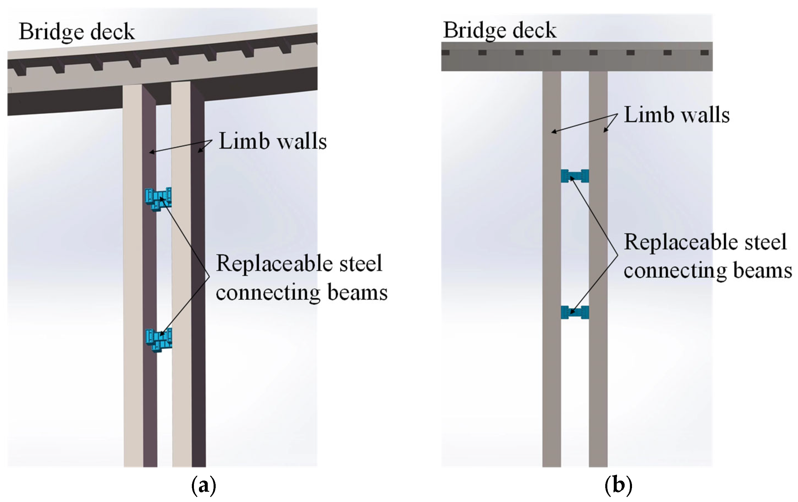
2. Design Concept and Failure Modes of the Innovative DLTW-RSCBs

The innovative double-limb-thin-wall (DLTW) bridge pier with replaceable steel connecting beams (DLTW-RSCBs) is composed of two thin-limb-wall columns in the longitudinal direction of the bridge structure and replaceable steel connecting beams (RSCBs) between them, as illustrated in Figure 1. The RSCBs in the novel DLTW pier are designed to dissipate seismic energy, protect the main structure (columns), and enhance longitudinal seismic resistance of the rigid-frame bridge.
The schematic diagram and design concept of the DLTW-RSCBs are shown in Figure 2a. In the DLTW-RSCBs, the connecting beams (CBs) are designed to be weaker than the thin-limb-wall columns; thus, they will yield earlier to protect columns. The DLTW-RSCBs are designed to work as follows: (1) In the elastic stage, the main structure (i.e., the limb-wall column) remains elastic at small deformation, while the connecting beams (CBs) may yield in this stage; the piers need not be repaired, as the main structure remains elastic. (2) In the repairable stage, the longitudinal bars yield, and the damage to the limb-wall columns develops with increasing loading displacement but does not exceed the moderate damage states described in [43], i.e., the crack widths at the limb-wall columns do not exceed 2 mm. According to whether the crack widths of the column bottom reach 1 mm, the DLTW pier is divided into slight and moderate damage states [43], corresponding to the rapid repair stage and costly repairable stage, respectively. The RSCBs undergo plastic deformation to dissipate seismic energy but can still be replaced; the main structure has endured moderate damage, and the pier can be costly to repair at this stage. (3) In the non-collapse stage, as the loading displacement further increases, significant spalling of the cover concrete is observed at the bottom of the limb-wall columns, accompanied by failure of the CBs. The repair of the piers becomes very difficult or impossible, but the force transmission path is still integral, and the piers still have bearing or deformation capacity to avoid collapse. (4) In the collapse stage, the thin-limb-wall columns will fail in an extraordinarily extreme circumstance, and then the collapse of the piers is reduced. A detailed description of the failure mechanism of the DLTW-RSCBs is shown in Figure 2b.

3. Experimental Program

3.1. Specimen Design

A continuous rigid-frame bridge with double-limb-thin-wall (DLTW) piers in northern China was selected as the prototype bridge. As this study is mainly focused on the longitudinal mechanical properties of DLTW piers, and due to the limitations of loading equipment, half of the transversal direction of the prototype bridge was selected in the model design, as depicted in Figure 3.
In this study, three 1/6.875 scaled DLTW piers, a conventional DLTW pier with no beams (DLTW-NBs) based on the prototype bridge, a DLTW pier with RC connecting beams (DLTW-RCCBs), and an innovative double-limb-thin-wall (DLTW) bridge pier with replaceable steel connecting beams (DLTW-RSCBs) were designed. The three specimens have the same double-limb-thin-wall columns, while the only difference is the connecting beams, and the detailed design parameters are shown in Table 1. The geometric dimensions and reinforcement details of the specimens are shown in Figure 4, of which Figure 4a depicts the DLTW-NB specimen, while the left side and right side of Figure 4b are half of the DLTW-RCCBs and DLTW-RSCBs specimens, respectively.
The three pier specimens adopted the same double-limb-thin-wall columns, for which detailed descriptions of the reinforcement layouts and reinforcement ratios are listed in Table 2.
To compare the effects of connecting beams (CBs) on the seismic performance of DLTW piers, the RCCB and RSCB were designed to have the same shear strength. The detailed design parameters of the RCCB and RSCB are shown in Table 3.
The design shear capacity (Vcs) of the RCCB was calculated according to Equation (1) [44]:
V c s = 0.45 × 10 3 α 1 α 2 α 3 b h 0 2 + 0.6 P f c u , k ρ s v f s v + 0.6 ρ s v f s v
where ρsv and fsv (Mpa) are the reinforcement ratio and yield strength of the transverse reinforcement, respectively, and fcu,k (Mpa) is the cubic compressive strength of concrete. B (mm) and h0 (mm) are the width and height of the cross section, respectively, while P (N) is the axial load. A1, α2, and α3 are the parameters. According to the design parameters of the RCCB, the calculated design shear capacity (Vcs) of the RCCB is 145.22 kN.
The RSCBs were composed of rigid segments at both ends and energy-dissipation segments in the middle, of which M12 high-strength bolts were used to connect them at the end plates, as shown in Figure 5. The rigid segments were embedded in and connected rigidly with the limb-wall columns, which is conducive to increasing the deformation of the energy-dissipation segment and replacing the energy-dissipation segments after the earthquake. Double-sided fillet welds were adopted to connect the segments of H-shaped steel.
The RSCB was designed according to the American seismic specification for steel structures (ANSI/AISC 341-10) [45] and the Chinese code for seismic design of buildings (GB 50011-2010) [46]. The shear-span ratio (e/(Mlp/Vlp)) was calculated using Equation (2):
V l p · e M l p = 0.6 f y A w · e f y W
where V l p (N), M l p (N·mm), and e (mm) are the plastic shear capacity, plastic bending capacity, and length of the energy-dissipation segment, respectively, and fy (Mpa), Aw (mm2), and W (mm3) are the yield strength of steel, shear section area, and moment resistance of the steel connecting beam, respectively. The energy-dissipation segments have a shear-span ratio, e/(Mlp/Vlp), equal to 1.2, which is smaller than 1.6 and expected to yield primarily in shear [45].
The plastic shear capacity and plastic bending capacity of the rigid segment were designed in accordance with Equations (3) and (4):
M b p Ω V n l / 2
V b p Ω V n
where Mbp (N·mm) and Vbp (N) are the plastic shear capacity and plastic bending capacity of the rigid beam segment, respectively; l (mm) is the clear span of the RSCB; and Ω is the overstrength factor. According to the recommendation in [47], the overstrength factor is taken as 1.5~1.9 when the shear-span ratio of the energy-dissipation segment is greater than 1.0. The design shear capacity (Vmax) of the RSCB is equal to 146.35 kN according to the calculation method expressed in Equations (5) and (6):
V m a x = Ω V n
V n = m i n ( V l p , 2 M l p / e )

3.2. Material Properties

The reinforcement and concrete of the specimens are the same as the prototype bridge, of which the HRB400 reinforcement and C40 concrete were adopted for columns, while Q235 steel (with a yield strength of 235 MPa) was used for the RSCBs. Three 150 mm standard cubic specimens were poured and cured under the same conditions as the pier specimens. The average values of three measured cubic specimens are defined as the mechanical properties of the concrete material. The measured cubic compressive strength and elastic modulus of the concrete material are 38.1 MPa and 3.31 × 10⁴ MPa, respectively. The mechanical properties of the reinforcements and steel material used in this research are listed in Table 4.

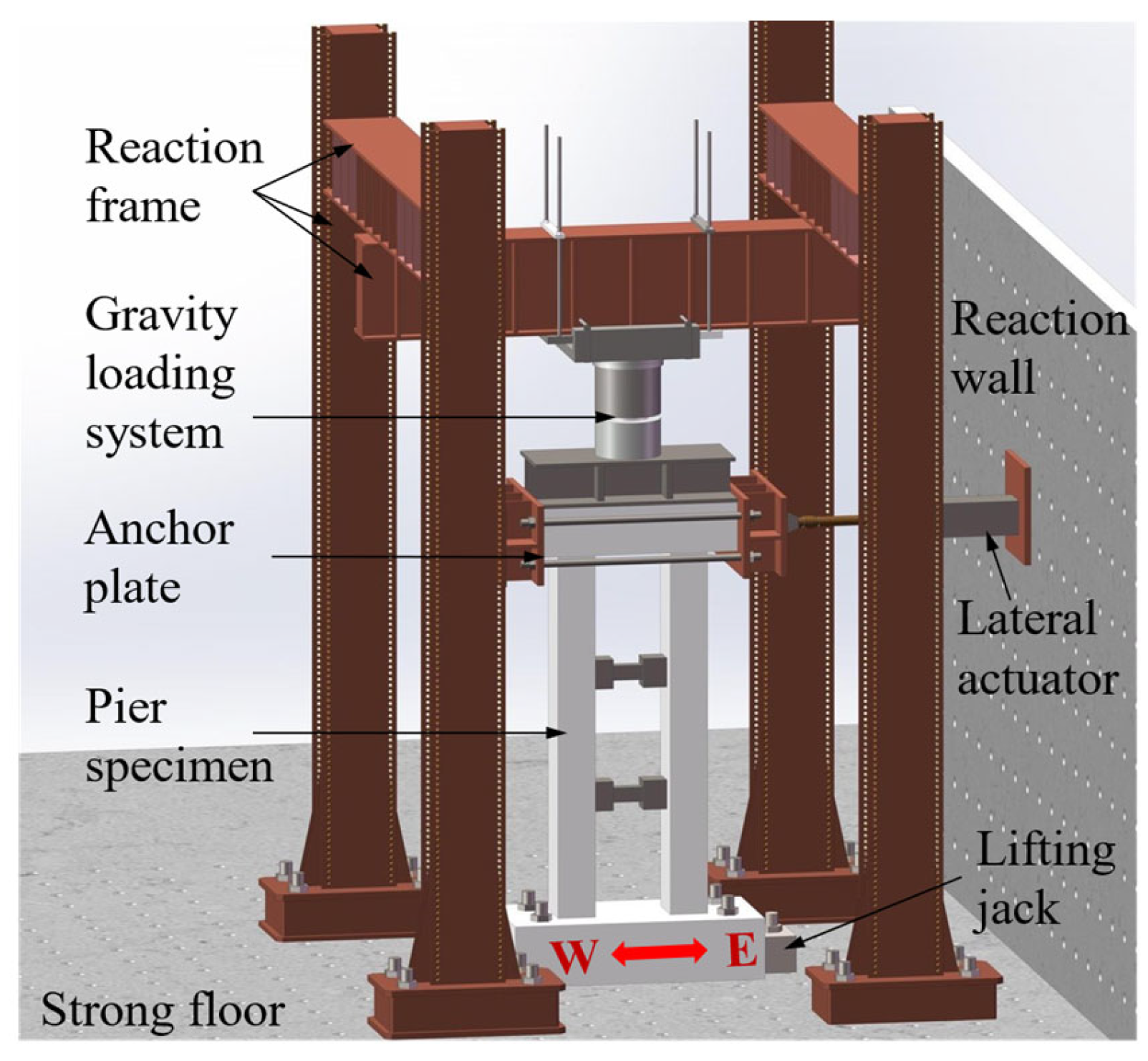
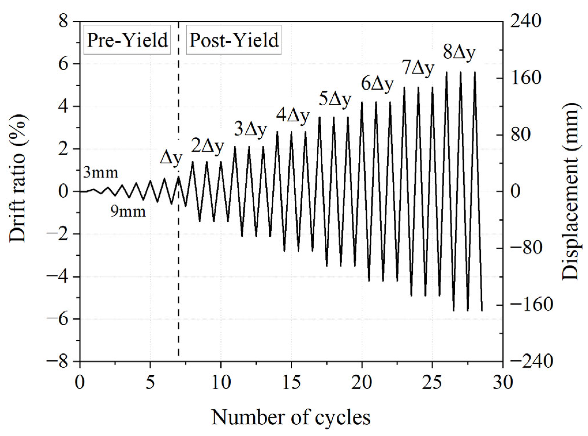
3.3. Test Setup and Loading Protocol

Quasistatic tests were carried out in the laboratory of the Institute of Engineering Mechanics, China Earthquake Administration, and the test setup is illustrated in Figure 6. The pier specimens were fixed to the ground with anchor bolts, and two jacks were installed at two sides of the bearing cap in the loading direction to prevent horizontal sliding of the base. A constant axial load with a typical axial compression ratio of 0.1 [48] was first applied on the top of the cap beam through the vertical actuator. Then, horizontal reversed loading was exerted on the cap beam by a displacement-controlled horizontal actuator, and the loading protocols are shown in Figure 7.
Displacement loading was adopted in this test, for which the loading protocol was determined by referring to the FEMA 461 code [49] and the Chinese specification for seismic testing of buildings (JGJ/T101-2015) [50]. The initial loading displacement was 3 mm, and the increase amplitude of the loading displacement was 3 mm until yielding displacement (i.e., steel yield of longitudinal bars at column bottom). After the yield point, the yield displacement was selected as the increased amplitude of the loading displacement, and three repeated loading times were conducted for each loading displacement to consider the strength degradation. The loading ended with specimen failure, which is defined as the point when the horizontal bearing capacity drops to 85% of the maximum bearing capacity. To facilitate a comparison, the DLTW-RCCBs and DLTW-RSCBs specimens adopted the same loading protocol as the DLTW-NBs specimen.

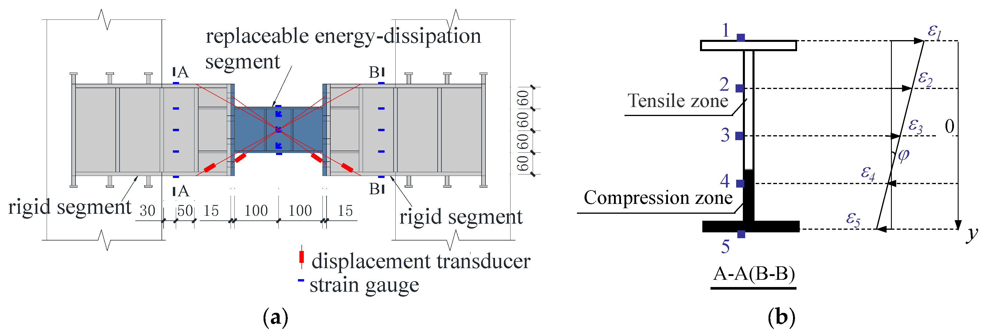
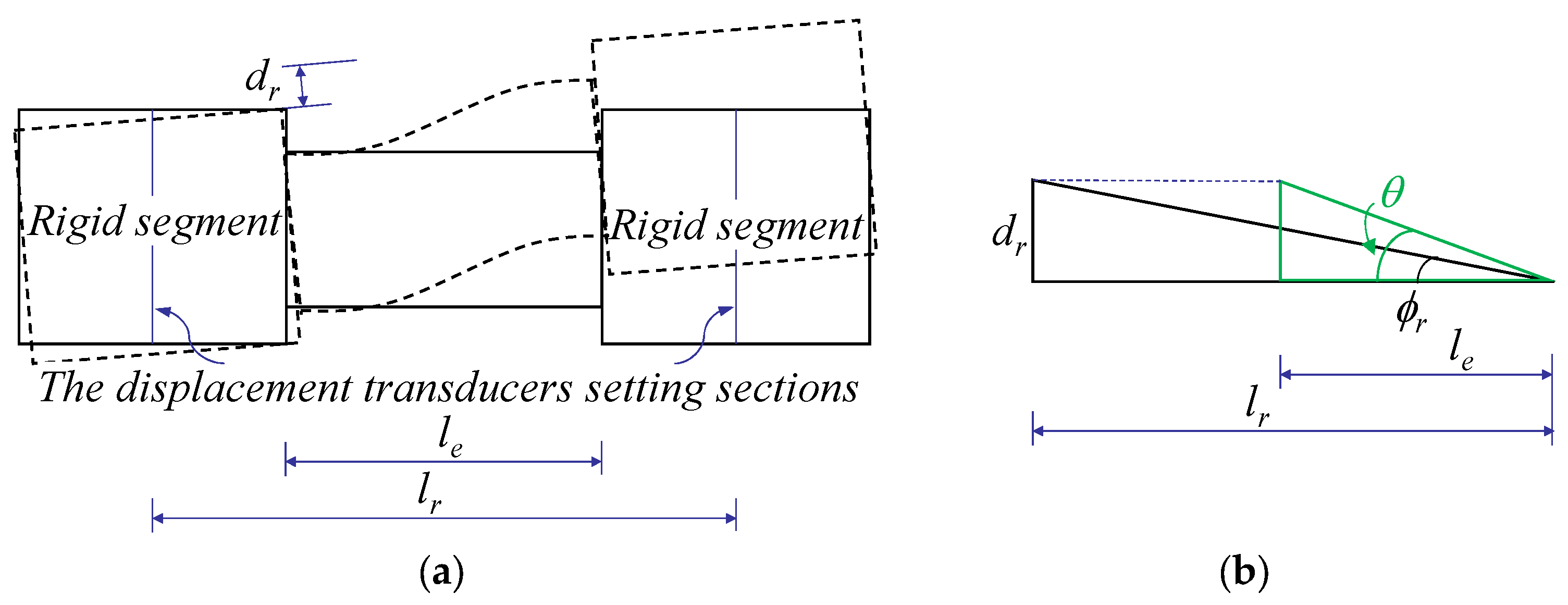
3.4. Arrangement of the Measurement Points

The strain gauges were arranged on the reinforcements at the plastic hinge region and at the joint with connecting beams of the thin-limb-wall columns to monitor the reinforcement strains of the limb-wall columns. The displacement transducers were arranged at the center of the cap beam to capture the actual horizontal loading displacement. Meanwhile, the horizontal and vertical displacement transducers were arranged at the base top to monitor the horizontal slide and vertical rotation of the base. The displacement transducers were arranged at both sides of the plastic hinge regions of the limb-wall columns to measure the curvature distribution of the columns. The detailed arrangement of the strain gauges and displacement transducers for the limb-wall columns are illustrated in Figure 4.
A series of measurement points were laid out on the connecting beams (CBs) to study the response of the CBs. For RCCBs, the strain gauges were arranged at the reinforcement of the CBs to measure the reinforcement strains of the concrete connecting beam, for which a detailed layout is shown in Figure 4b.
The arrangement of the strain gauges and displacement transducers of the RSCB are shown in Figure 8a. Figure 8b shows the schematic diagram for the internal force calculation of Section A or B. The shearing force of the RSCBs can be derived from the measured strain, as expressed in Equations (7)–(9):
φ = ε i ε j y i , j
M = E I φ
V = ( M A M B ) / l A B
where ε i and ε j are the bending strains of the Section A or B, i,j = 1,2,3,4,5 (Figure 8); yi,j (mm) is the distance between the two strain gauges; ϕ (mm−1) is the curvature of section A or B; E (MPa), I (mm4) and, l A B (mm) are the elastic modulus, moment of inertia, and distance between two rigid sections (Sections A and B), respectively; and M (N·mm) and V (N) are the bending moment and shearing force, respectively.
The rotation of the RSCBs can be derived from the displacement values, as expressed in Equations (10) and (11):
θ = d r l e = ϕ r l r l e
ϕ r = arcsin ( Δ 1 Δ 2 ) 2 l r h r · l r 2 + h r 2 ( Δ 1 Δ 2 ) 2 4
where θ (rad) and ϕr (rad) are the rotations of the two end plates and the two sections of the two cross displacement transducers of rigid segments, respectively; Δ1 (mm) and Δ2 (mm) are the displacement data measured by the two cross displacement transducers setting on the two rigid segments, respectively; lr (mm) is the horizontal distance between the two cross displacement transducers setting sections on the rigid segments; le (mm) is the horizontal distance between the two end plates of the rigid segments; and hr (mm) is the web height of the rigid segments.
The schematic diagram of the CB rotation solution is shown in Figure 9. Considering the replaceability of the energy-dissipation segments, the residual rotation (ϕr) limit of end plates of the two rigid segments is 0.03 rad calculated using geometric analysis (Figure 9).

4. Test Observation and Failure Modes

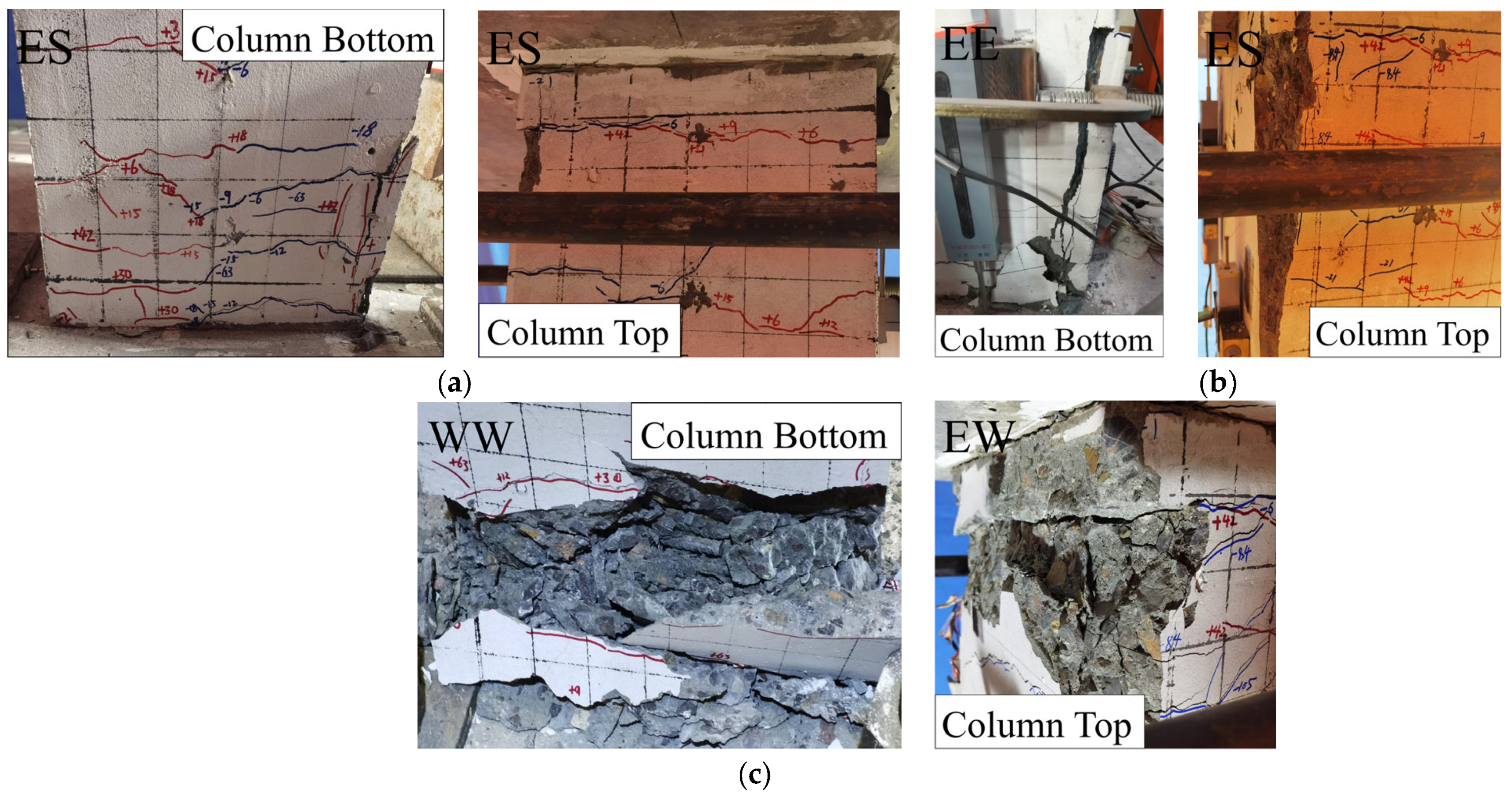
4.1. DLTW-NB Specimen

Horizontal cracks were first observed at the bottom of the limb-wall columns at the loading displacement of 3 mm. The longitudinal bars of the columns began to yield when the loading displacement reached 0.61% drift ratio (18 mm), while inclined cracks were observed at the bottom of the thin-limb-wall columns. The crack widths gradually increased with increasing loading displacement. Vertical cracks appeared, and minor spalling of the cover concrete was observed at the bottom of the east limb-wall column when the loading displacement reached 1.4% drift ratio (42 mm). With increasing loading displacement, the spalling of the cover concrete further increased, as shown in Figure 10a,b. The concrete cover completely spalled, and the longitudinal bar was exposed at the bottom of the west limb-wall columns at the third cycle of the 4.9% drift ratio (147 mm), while fracture of the stirrups and buckling of longitudinal bars were observed at the same time, as shown in Figure 10c. Since the lateral bearing capacity of the DLTW-NBs dropped below 85% of the maximum bearing capacity, this structure was considered to be damaged. The damage was concentrated in the plastic hinge area, i.e., the top and bottom of two thin-limb-wall columns.
The DLTW-NBs showed typical flexural failure characteristics, and the distribution of cracks and overall deformation of the piers at failure are shown in Figure 11.

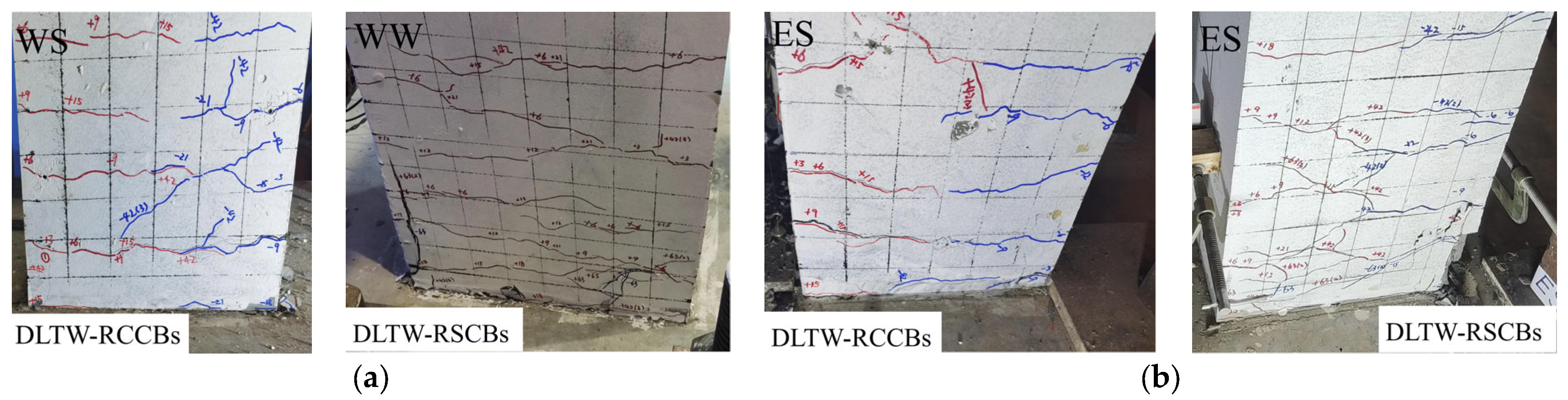
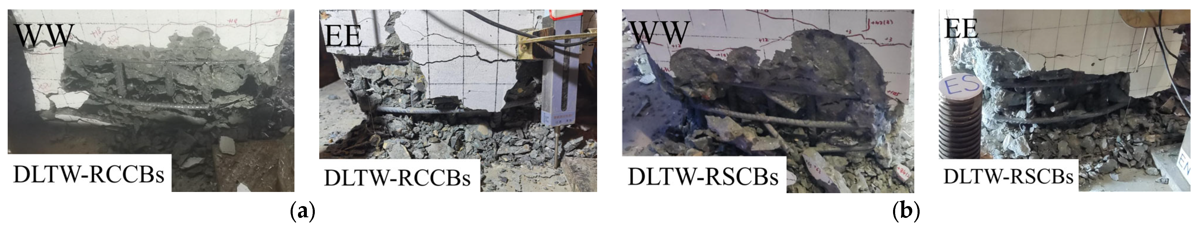
4.2. DLTW-RCCBs and DLTW-RSCBs Specimens

Horizontal cracks were first observed at the bottom of the DLTW-RCCBs and DLTW-RSCBs specimens at the loading displacement of 3 mm. Meanwhile, vertical tensile cracks appeared at the ends of the RCCBs. The cracks in the RCCBs gradually developed to the neutral axis with increasing loading displacement. The longitudinal bars yielded, and diagonal cracks occurred in the RCCBs at 0.48% drift ratio (14.5 mm) (Figure 12a), while the steel material of the RSCBs yielded at 0.52% drift ratio (15.6 mm). At the same time, the limb-wall columns remained elastic; therefore, the RCCBs and RSCBs yielded at first to dissipate the seismic energy and protect the main structure (limb-wall columns). The crossing cracks were observed at the ends of the limb-wall columns for the specimens of DLTW-RCCBs and DLTW-RSCBs at a drift ratio of 1.4% (42 mm), while it occurred at the drift of 0.7% (21 mm) for the DLTW-NBs specimen. Meanwhile, the west limb-wall columns exhibited 0.03 mm tensile cracks in the joint region of the DLTW-RSCBs specimen.
The connecting beams (CBs) of the DLTW-RCCBs and DLTW-RSCBs specimens presented serious damage at 2.1% drift ratio (63 mm). The RCCBs presented distinct sheared failure in which significant spalling of the cover concrete and exposure of longitudinal bars were observed, as shown in Figure 12. The flange plates of the RSCBs exhibited bending deformation, and 0.06 mm tensile cracks emerged in the joint region of the east limb-wall columns. The concrete cover of the limb-wall columns basically remained intact for the DLTW-RCCBs and DLTW-RSCBs specimens at the drift ratio of 2.1%, while it spalled off for the DLTW-NBs specimen at the same drift ratio. The damages to the column bottoms of the DLTW-RCCBs and DLTW-RSCBs specimens are shown in Figure 13. It can be observed from the comparisons that due to the protection of CBs, the damage to the limb-wall columns of the DLTW-RCCBs and DLTW-RSCBs specimens was lower than that of the DLTW-NBs specimen at the same drift ratio.
The junction between the flange and end plates of the steel energy-dissipation segment exhibited cracks at 4.2% drift ratio (126 mm), as shown in Figure 14. The RSCBs gradually failed and lost energy-dissipation capacities with increasing loading displacement, indicating that the damage to the limb-wall columns was rapidly aggravated.
Both piers finally failed at 4.9% drift ratio (147 mm) when the bearing capacity dropped below 85% of the maximum bearing capacity. In this stage, the cover concrete completely spalled off, and the core concrete was crushed in the plastic hinge region. The stirrup presented obvious bending deformation, and buckling of the longitudinal bars was observed, as shown in Figure 15.
The two piers presented typical bending failure, and plastic hinges formed at the top and bottom of the limb-wall columns, accompanied by shear failure of the RCCBs and RSCBs, respectively. The crack distributions and overall view of the damage failure of the DLTW-RCCBs and DLTW-RSCBs are shown in Figure 16.

5. Test Results and Analysis

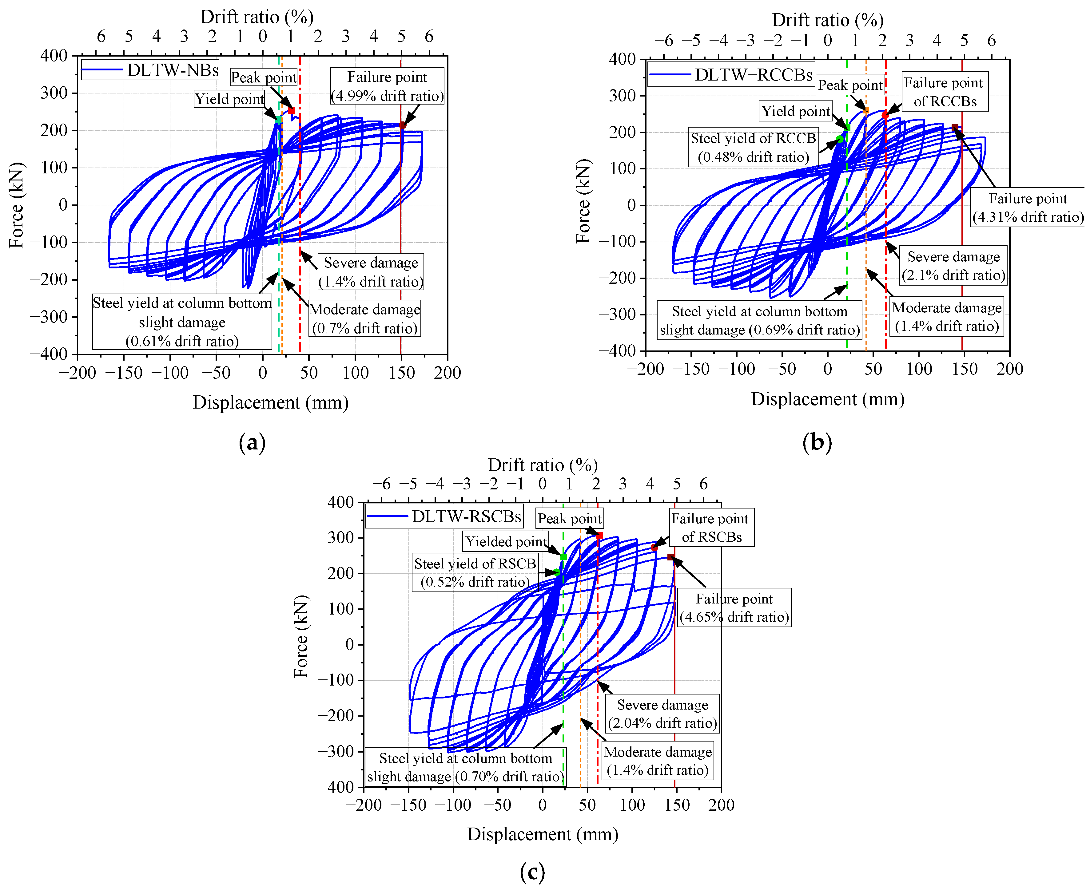
5.1. Hysteretic Curves

The load-displacement hysteretic curves of the DLTW-NBs, DLTW-RCCBs, and DLTW-RSCBs specimens are shown in Figure 17. It can be observed that the hysteretic curves of all three piers are plump and exhibit minor pinching effects. The use of connecting beams (CBs) can improve the bearing capacity of the piers. Before the failure of the CBs, the strength degradation is slower, and the hysteretic curves are plumper for the DLTW-RCCBs and DLTW-RSCBs specimens than for the DLTW-NBs specimen.

5.2. Skeleton Curves and Ductility

The comparisons of the skeleton curves between the three piers are shown in Figure 18.
Moreover, the key seismic performance indicators, including yield displacement (Δy), maximum bearing capacity (Fm), ultimate displacement (Δu), and displacement ductility (μΔ), were calculated to better compare the seismic performance of the different piers. The yield displacement (Δy) was defined as the point when the yield of longitudinal bars at the column bottom was observed. Moreover, the yield of the longitudinal bars in the RCCB and the steel material in the RSCB were also calculated, which were defined as the yield of the CBs. The ultimate displacement was defined as the point when one of the following occurred: (1) The horizontal bearing capacity drops to 85% of the maximum bearing capacity. Or, (2) buckling and low-cycle fatigue fracture of longitudinal bars of column bottom occur. The displacement ductility (μΔ) was defined as the ratio of the ultimate displacement (Δu) to the yield displacement (Δy) (i.e., μΔ = Δuy). The seismic performance indicators are summarized in Table 5.
It can be observed from Figure 18 and Table 5 that the use of connecting beams (CBs) improved the horizontal bearing capacity of pier specimens, while the bearing capacity of the DLTW-RCCBs and DLTW-RSCBs specimens increased by 3.2% and 21.6% compared to the DLTW-NB specimen, respectively. The RCCBs and RSCBs yielded earlier than the limb-wall columns (i.e., the yield of the pier specimen) to protect the main structure (columns). Due to the protection of the CBs, the yields of the DLTW-RCCBs and DLTW-RSCBs specimens were slightly later than that of the DLTW-NBs specimen. The effects of the RSCBs on the increase in bearing capacity and yield displacement were more significant than those of the RCCBs.
The bearing capacity of the piers with connecting beams (CBs) decreased more slowly before the failure of the CBs. The bearing capacity of the DLTW-RCCBs and DLTW-RSCBs specimens began to decline more rapidly after drift ratio of 2.1% and 4.2%, respectively, when the shear failure of the RCCBs and RSCBs occurred. The ultimate displacements of the DLTW-RCCBs and DLTW-RSCBs specimens were slightly lower than that of the DLTW-NBs. However, the bearing capacities of the DLTW-RCCBs and DLTW-RSCBs specimens were still larger than that of the DLTW-NBs specimen until failure. Therefore, despite slightly lower ultimate displacement and ductility, the DLTW-RCCBs and DLTW-RSCBs specimens can be considered to have comparable deformation capacity. Furthermore, the ductility of all specimens exceeded 6, which means that all specimens had good ductility.

5.3. Hysteretic Performance of the Replaceable Steel Connecting Beam (RSCB)

The deformation of the replaceable steel connecting beam (RSCB) can be measured through the arranged displacement transducers, as described in Section 3.4. Based on the measured displacement data, the rotation and shearing force of the RSCB can be derived according to Equations (7)–(11). The obtained shearing force-rotation curve of the RSCB is shown in Figure 19.
As described in Section 4.2, the energy-dissipation segment of the RSCBs yielded at 0.52% drift ratio, after which the RSCBs entered the plastic to dissipate the seismic energy and protect the main structure. It can be observed from Figure 19 that the hysteretic loops of the RSCB are plump; thus, it has good energy-dissipation capacity. However, gaps exist between the end-plate connections of the energy-dissipation segment and the rigid segment, which are staggered and recovered during cyclic loading and generate the pinching effect of hysteretic curves, as marked in Figure 19. The cumulative energy dissipation of the RSCBs contributes 32.41% of the total energy dissipation of the DLTW-RSCB specimen.

5.4. Cumulative Hysteretic Dissipated Energy

Energy-dissipation capacity is an important seismic performance index of bridge piers. The cumulative hysteretic dissipated energy is the total energy the pier can dissipate during the test until failure. The comparisons of the cumulative hysteretic dissipated energy among the DLTW-NBs, DLTW-RSCBs, and DLTW-RCCBs specimens are shown in Figure 20. The comparisons show that the cumulative hysteretic dissipated energy of the DLTW-NBs specimen was larger than that of the DLTW-RSCBs and DLTW-RCCBs specimens at the same deformation before the drift ratio of 2.1%. This is because the use of connecting beams (CBs) increases the yield displacement and reduces the plastic deformation, thus reducing the energy dissipation of the DLTW-RSCBs and DLTW-RCCBs specimens. The plastic deformation of the connecting beams (CBs) began to increase with loading displacement and contributed to the total energy dissipation, whose contribution became increasingly significant after the drift ratio of 2.1%. The energy dissipation of the DLTW-RSCBs gradually surpassed that of the DLTW-NBs with increasing loading displacement due to the excellent energy-dissipation capacity of the RSCB. Although the deformation capacity of the DLTW-RSCBs was lower than that of the DLTW-NBs, the total energy dissipation of the DLTW-RSCBs was still 13.4% larger than that of the DLTW-NBs at 4.9% drift ratio when the DLTW-NBs failed. On the other hand, the energy dissipation of the DLTW-RCCBs specimen was lower than that of the DLTW-NBs specimen during the whole loading process due to the limited energy dissipation capacity of the RCCBs. Therefore, RSCBs can effectively improve the energy-dissipation capacity of the DLTW pier, which enhances the seismic performance of bridge piers.

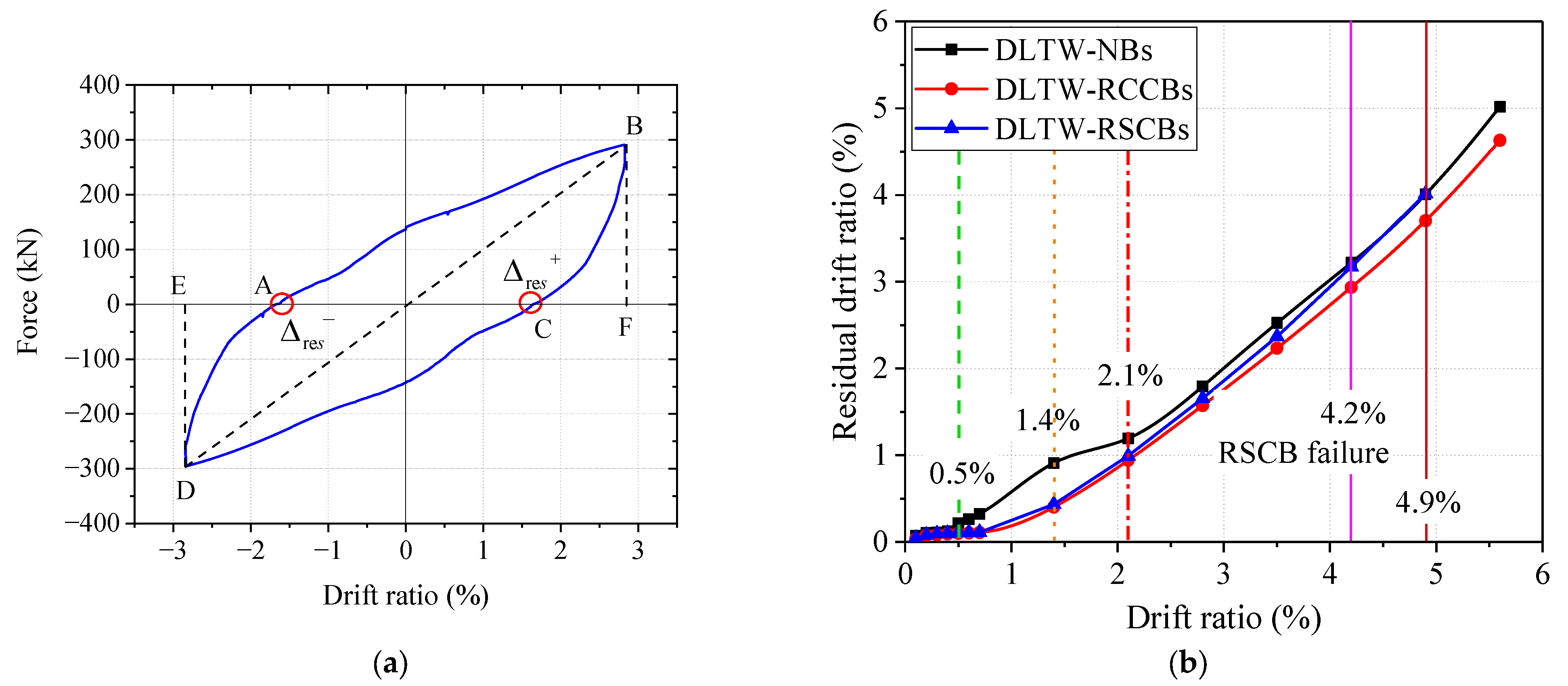
5.5. Residual Drift Ratio

The residual displacement can reflect the repairable capacity of bridge piers after earthquakes; therefore, it is an important performance index for evaluating the seismic resilience of bridge piers. The residual drift ratio (Δres±) herein is defined as the average value in the curve of one cycle of two loading directions, as shown in Figure 21a. The comparisons of the residual rift ratios between the three piers are shown in Figure 21b.
It can be observed from the figure that the use of connecting beams (CBs) can reduce the residual drift ratios of DLTW-RCCBs and DLTW-RSCBs specimens at the same total deformation but can improve elastic deformation and reduce plastic deformation of DLTW piers. However, the residual drift ratio of the DLTW-RSCBs specimen gradually increased as the damage to the RSCBs intensified. The residual drift ratio of the DLTW-RSCBs specimen was close to that of the DLTW-NBs specimen at the late loading stage and almost equal to that of the DLTW-NBs specimen after the complete failure of the RSCBs. On the other hand, the DLTW-RCCBs specimen had a lower residual displacement than the DLTW-NBs specimen during the whole loading process, as the RCCBs had not completely failed even at the late loading stage and could still reduce the residual drift ratio of the pier to some extent. Therefore, the use of connecting beams (CBs) can reduce the residual drift ratio and enhance the seismic resilience of DLTW piers, at least at the minor and moderate damage stages when CBs can still work.

6. Discussions

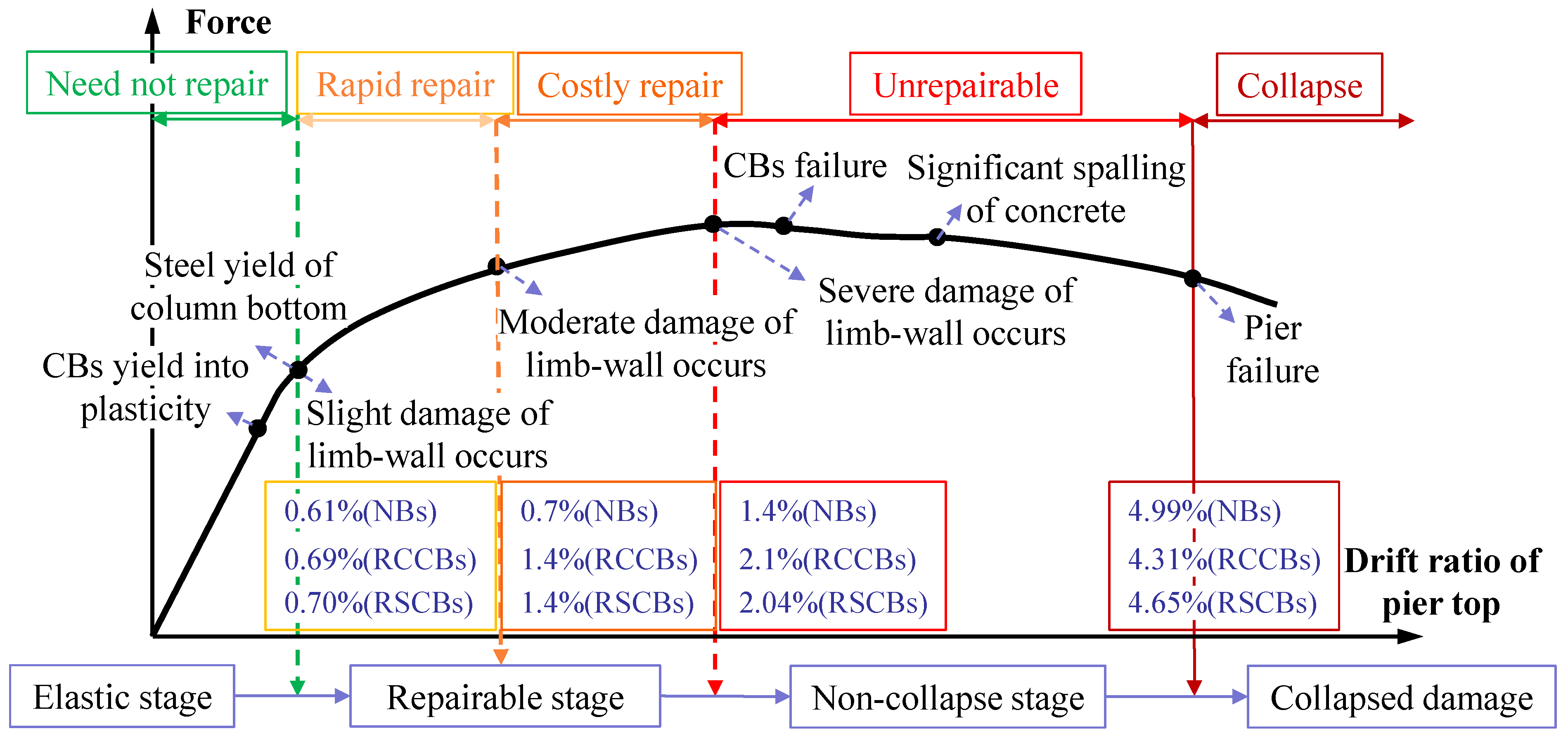
6.1. Comparisons of Damage Development

The comparisons of the damage development between the DLTW-NBs, DLTW-RCCBs and DLTW-RSCBs specimens are shown in Figure 22. The failure process of the piers can be divided into four stages, as described in Section 2. The repairability in the first three stages of the specimens is described as follows:
(1)
Elastic stage. The CBs yielded first, prior to the limb-wall columns, to protect the main structure (columns). As a result, the DLTW-RCCBs and DLTW-RSCBs specimens demonstrated larger elastic deformation than the DLTW-NBs specimen, while the increase in the amplitude of the DLTW-RSCBs specimen was larger. Therefore, the use of CBs improves the seismic resistance of the piers under small earthquakes (i.e., lower damage at the same deformation).
(2a)
Rapidly repairable stage. The crack widths of the limb-wall column bottom increased with increasing loading displacement and reached 1 mm [43] (i.e., entered a moderate damage state) at the drift ratio of 0.7% for the DLTW-NBs specimen. On the other hand, the DLTW-RCCBs and DLTW-RSCBs specimens just exceed the yield point and were still at the slight damage state. The crack widths of the DLTW-NBs specimen reached 2 mm [43], and repair was difficult (serious damage) at 1.4% drift ratio, while the DLTW-RCCBs and DLTW-RSCBs specimens were still in a moderate damage state and could be conveniently repaired.
(2b)
Costly repairable stage. The RCCBs were severely destroyed, and the DLTW-RCCBs specimen entered a serious damage state at the drift ratio of 2.1%. On the other hand, the RSCBs could still be replaced despite the damage deformation when the limb-wall columns began to enter serious damage at 2.04% drift ratio, before which the limb-wall columns could still be repaired with great effort. Therefore, the use of connecting beams (CBs) can reduce the damage of piers before the failure of connecting beams (CBs), and the RSCBs can be replaced more conveniently than the RCCBs after damage failure.
(3)
Non-collapse stage. The RCCBs were severely damaged at the initial stage of serious damage (drift ratio of 2.1%) for the DLTW-RCCBs specimen, while the damage to the RSCBs gradually intensified with increasing loading displacement after the drift ratio of 2.1%. The damage of the limb-wall columns for the DLTW-RCCBs and DLTW-RSCBs specimens gradually increased with the damage development of the connecting beams (CBs). Additionally, their failure modes after the failure of CBs were similar to those of the DLTW-NBs specimens, as these three specimens have the same structure type. The buckling and low-cycle fatigue fracture of the longitudinal bars at the column bottom finally caused the failure of all three bridge piers, i.e., collapse. As the CBs already completely failed, and the failure of columns controls the final damage of the bridge pier, the use of the CBs does not improve the ultimate displacement of DLTW piers.

6.2. Repairability of the Replaceable RSCBs

The residual rotations of the replaceable RSCBs at the end of loading were measured for the DLTW-RSCBs specimen, as listed in Table 6, in which RSCB-1 and RSCB-2 are the lower and upper connecting beams (CBs), respectively. It can be observed from the table that the residual rotations of the rigid segment end plates for both RSCBs were smaller than 0.02 rad, and the rigid sections remained elastic. The damage of the RSCBs was mainly concentrated on the energy-dissipation segments. The minor residual rotations of rigid sections allowed for the reinstallation of the new energy-dissipation segments without additional fabrication, such as welding or post drilling bolt holes.
To evaluate the repairability of the RSCBs, two technicians tried to replace the energy-dissipation segments of the RSCBs after the end of loading, for which replacement times are also listed in Table 6. It can be observed from the table that the energy-dissipation segments of two RSCBs can be replaced in approximately one hour. Therefore, the proposed innovative DLTW-RSCBs can achieve rapid replacement of RSCBs and enhance the seismic resilience of the DLTW pier, thereby avoiding unnecessary construction and resource consumption.

7. Conclusions

An innovative double-limb-thin-wall (DLTW) bridge pier with longitudinal replaceable steel connecting beams (DLTW-RSCBs) is proposed in this paper. Quasistatic tests of the proposed innovative DLTW-RSCBs, a conventional DLTW pier with no beams (DLTW-NBs), and a DLTW pier with RC connecting beams (DLTW-RCCBs) were conducted to investigate the longitudinal seismic performance of the proposed novel DLTW pier. The main conclusions are summarized as follows:
(1)
The use of the connecting beams (CBs) can improve the bearing capacity of the DLTW piers, of which the DLTW-RCCBs and DLTW-RSCBs specimens are 3.2% and 21.6% larger than the DLTW-NBs specimen, respectively. The DLTW piers with CBs have larger yield displacement and elastic deformation than the DLTW-NBs specimen, of which the increased amplitude of the DLTW-RSCBs specimen is larger than that of the DLTW-RCCBs. This is because steel/reinforcement of the CBs yields earlier than limb-wall columns and then dissipates seismic energy and protects the main structure (columns) from plastic damage. The ultimate displacements of the DLTW-RCCBs and DLTW-RSCBs specimens are 14% and 6.8% lower than that of the DLTW-NBs specimen, respectively. The decreased amplitudes of the displacement ductility are larger than the ultimate displacement because of the increase in yield displacement.
(2)
The cumulative dissipated energies of the DLTW-RCCBs and DLTW-RSCBs specimens are lower than that of the DLTW-NBs specimen at the initial loading stage because the use of CBs enhances the yield deformation and reduces the plastic deformation of DLTW piers. However, due to the excellent energy dissipation capacity of RSCBs, the cumulative dissipated energy of the DLTW-RSCBs gradually surpassed that of the DLTW-NBs with increasing loading displacement because the large plastic deformation of the RSCBs can facilitate energy dissipation to the DLTW pier. In contrast, the DLTW-RCCBs specimen has a lower energy dissipation capacity than the DLTW-NBs specimen during the whole loading process due to the poor energy dissipation capacity of RCCBs.
(3)
Due to the protection of the CBs, the damage degrees to the DLTW-RCCBs and DLTW-RSCBs specimens are lower than that of the DLTW-NBs specimen at the same drift ratio before the failure of the CBs. For example, the DLTW-NBs entered moderate damage and serious damage at drift ratios of 0.7% and 1.4%, respectively, while the DLTW-RCCBs and DLTW-RSCBs specimens were still at slight and moderate damage, respectively, at the corresponding drift ratios. Furthermore, the DLTW-RCCBs and DLTW-RSCBs specimens have lower residual drift ratios than the DLTW-RSCBs at slight and moderate damage states and are easier to repair. However, the use of CBs cannot reduce the damage of DLTW piers at the failure stage, as the CBs have already been completely destroyed, and the failure of columns controls the final damage of the DLTW piers. As a result, the residual drift ratio of the DLTW-RSCBs specimen is also close to that of the DLTW-NBs specimen at the failure point.
(4)
The damage of the connecting beams (CBs) for the DLTW-RSCBs specimen is mainly concentrated at the energy dissipation segments and can be replaced approximately 1 h after damage failure. Compared with conventional DLTW-NBs and DLTW-RCCBs, the proposed innovative DLTW-RSCBs demonstrate better seismic performance, such as larger lateral bearing capacity and energy-dissipation capacity, lower residual drift ratio, and seismic damage before severe damage states, as well as better repairability. Therefore, the proposed DLTW-RSCBs can improve the longitudinal seismic resistance of rigid-frame bridges, and they can reduce the repair costs of bridge structures under earthquake loading, which are valuable for the sustainability during their whole service lives.
(5)
Although the use of RSCBs can improve seismic performance and reduce the damage development of DLTW piers to some extent, the main structures (limb-wall columns) of the DLTW piers still unavoidably endure serious damage and are difficult to repair under strong earthquakes. Therefore, further work should be conducted to reduce residual deformation and improve the seismic resilience of DLTW piers under moderate and strong earthquakes. A reasonable combination of rocking and RSCBs in DLTW piers may be a good choice.

Author Contributions

Conceptualization, J.G.; methodology, J.G.; software, L.N. and R.S.; validation, J.G., L.N. and R.S.; formal analysis, J.G., L.N. and J.S.; investigation, J.G., L.N. and R.S.; resources, J.G.; data curation, L.N. and R.S.; writing—original draft preparation, L.N.; writing—review and editing, J.S.; supervision, J.G.; project administration, J.G.; funding acquisition, J.G. All authors have read and agreed to the published version of the manuscript.

Funding

The work presented in this paper was sponsored by the National Natural Science Foundation of China (Grant No. 52178493), Open Funding of Key Laboratory of Roads and Railway Engineering Safety Control (Shijiazhuang Tiedao University), Ministry of Education (STDTKF202021), S&T program of Hebei (Grant No. 21375402D), and the Natural Science Foundation of Hebei Province (Grant No. E2022210028). The writers wish to express their sincere gratitude to the sponsors.

Institutional Review Board Statement

Not applicable.

Informed Consent Statement

Not applicable.

Data Availability Statement

If anyone needs data for this study, you can contact the authors to obtain it.

Acknowledgments

The work presented in this paper was sponsored by the National Natural Science Foundation of China (Grant No. 52178493), Open Funding of Key Laboratory of Roads and Railway Engineering Safety Control (Shijiazhuang Tiedao University), Ministry of Education (STDTKF202021), S&T program of Hebei (Grant No. 21375402D), and the Natural Science Foundation of Hebei Province (Grant No. E2022210028). The writers wish to express their sincere gratitude to the sponsors.

Conflicts of Interest

The authors declare that they have no known competing financial interests or personal relationships that could influence the work reported in this paper.

Abbreviations

DLTWDouble-Limb-Thin-Wall
RSCBsReplaceable Steel Connecting Beams
DLTW-RSCBsDLTW Pier With RSCBs
RCReinforced Concrete
DLTW-RCCBsDLTW Pier With RC Connecting Beams
CBsConnecting Beams
BRBsBuckling-Restrained Braces
VDBViscous Damper Braces
PBSCsPiston-Based Self-Centering Braces
DRCLBDual-Replaceable Composite Link Beam
SSSteel Sleeve
GCMDGrouted Corrugated-Metal Duct
SCEDSelf-Centering Energy-Dissipation
SC-BRBSelf-Centering BRB
SCSFSelf-Centering Slip Friction
DLTW-NBsDLTW Pier With No Beams

Nomenclature

VcsDeign shear capacity
ρsvReinforcement ratio of transverse reinforcement
fsvYield strength of transverse reinforcement
fcu,kCubic compressive strength of concrete
BWidth of the cross section
h0Height of the cross section
PAxial load
VlpPlastic shear capacity of the energy-dissipation segment
MlpPlastic bending capacity of the energy-dissipation segment
eLength of the energy-dissipation segment
fyYield strength of steel
AwShear section area of the steel connecting beam
WMoment resistance of the steel connecting beam
MbpPlastic shear capacity of the rigid beam segment
VbpPlastic bending capacity of the rigid beam segment
lClear span of the RSCB
Ω The overstrength factor
εiBending strains of the Section A or B
yi,jDistance between the two strain gauges
ϕCurvature of section A or B
EElastic modulus
IMoment of inertia
lABDistance between two rigid sections
MBending moment
VShearing force
θRotations of the two end plates
ϕrRotations of two sections of the two cross displacement transducers
ΔiDisplacement data, i = 1,2
liHorizontal distance between the two cross displacement transducers
hrWeb height of the rigid segment
ΔyYield displacement
FmMaximum bearing capacity
ΔuUltimate displacement
μΔDisplacement ductility
Δres±Residual drift ratio

References

  1. Peng, Y.; Zhang, Z. Development of a novel type of open-web continuous reinforced-concrete rigid-frame bridge. J. Bridge Eng. 2020, 25, 05020005. [Google Scholar] [CrossRef]
  2. Wang, H.; Xie, C.; Liu, D.; Qin, S. Continuous reinforced concrete rigid-frame bridges in China. Pract. Period. Struct. Des. Constr. 2019, 24, 05019002. [Google Scholar] [CrossRef]
  3. Yuan, W.; Hu, B.; Fan, L. Seismic capacity and assessment of column piers. J. Tongji Univ. Nat. Sci. 1996, 21, 601. (In Chinese) [Google Scholar]
  4. Billah, A.H.M.M.; Alam, M.S. Seismic performance evaluation of multi-column bridge bents retrofitted with different alternatives using incremental dynamic analysis. Eng. Struct. 2014, 62, 105–117. [Google Scholar] [CrossRef]
  5. Wu, R.Y.; Pantelides, C.P. Seismic evaluation of repaired multi-column bridge bent using static and dynamic analysis. Constr. Build. Mater. 2019, 208, 792–807. [Google Scholar] [CrossRef]
  6. Pantelides, C.P.; Ward, J.P.; Reaveley, L.D. Behavior of R/C bridge bent with grade beam retrofit under simulated earthquake loads. Earthq. Spectra 2004, 20, 91–118. [Google Scholar] [CrossRef]
  7. Aloisio, A.; Pelliciari, M.; Alaggio, R.; Nuti, C.; Fragiacomo, M.; Briseghella, B. Structural robustness of an RC pier under repeated earthquakes. Proc. Inst. Civ. Eng.-Bridge Eng. 2022, 1–8. [Google Scholar] [CrossRef]
  8. Paolacci, F.; Giannini, R. An experimental and numerical investigation on the cyclic response of a portal frame pier belonging to an old reinforced concrete viaduct. Earthq. Eng. Struct. Dyn. 2012, 41, 1109–1127. [Google Scholar] [CrossRef]
  9. Xia, Z.; Ge, J.; Lin, Y.; Qiu, F. Shake table study on precast segmental concrete double-column piers. Earthq. Eng. Eng. Vib. 2020, 19, 705–723. [Google Scholar]
  10. Upadhyay, A.; Pantelides, C.P. Fragility-informed seismic design of multi-column bridge bents with post-tensioned concrete columns for accelerated bridge construction. Eng. Struct. 2022, 269, 114807. [Google Scholar] [CrossRef]
  11. El-Bahey, S. Analytical Development and Experimental Validation of a Structural-Fuse Bridge Pier Concept; State University of New York at Buffalo: Buffalo, NY, USA, 2010. [Google Scholar]
  12. El-Bahey, S.; Bruneau, M. Buckling restrained braces as structural fuses for the seismic retrofit of reinforced concrete bridge bents. Eng. Struct. 2011, 33, 1052–1061. [Google Scholar] [CrossRef]
  13. Chen, X.; Li, C. Seismic assessment of tall pier bridges with double-column bents retrofitted with buckling restrained braces subjected to near-fault motions. Eng. Struct. 2021, 226, 111390. [Google Scholar] [CrossRef]
  14. El-Bahey, S.; Bruneau, M. Bridge piers with structural fuses and bi-steel columns. I: Experimental testing. J. Bridge Eng. 2012, 17, 25–35. [Google Scholar] [CrossRef]
  15. El-Bahey, S.; Bruneau, M. Bridge piers with structural fuses and bi-steel columns. II: Analytical investigation. J. Bridge Eng. 2012, 17, 36–46. [Google Scholar] [CrossRef]
  16. Wang, Y.; Ibarra, L.; Pantelides, C. Seismic retrofit of a three-span RC bridge with buckling-restrained braces. J. Bridge Eng. 2016, 21, 04016073. [Google Scholar] [CrossRef]
  17. Bazaez, R.; Dusicka, P. Design implementation of buckling restrained braces for seismic retrofitting of reinforced concrete multi-column bridge bents. In Proceedings of the Structures Congress, Portland, OR, USA, 23–25 April 2015; Volume 2015, pp. 485–496. [Google Scholar]
  18. Bazaez, R.; Dusicka, P. Cyclic behavior of reinforced concrete bridge bent retrofitted with buckling restrained braces. Eng. Struct. 2016, 119, 34–48. [Google Scholar] [CrossRef]
  19. Wei, X.; Bruneau, M. Case study on applications of structural fuses in bridge bents. J. Bridge Eng. 2016, 21, 05016004. [Google Scholar] [CrossRef]
  20. Xie, W.; Sun, L.; Wei, J. Experimental study on seismic performance of bridge piers with structural fuses and its application. China J. Highw. Transp. 2014, 27, 59. [Google Scholar]
  21. Dong, H.; Du, X.; Han, Q.; Bi, K.; Hao, H. Hysteretic performance of RC double-column bridge piers with self-centering buckling-restrained braces. Bull. Earthq. Eng. 2019, 17, 3255–3281. [Google Scholar] [CrossRef]
  22. Monteiro, A.; Arede, A.; Vila-Pouca, N.; Peixoto, A.; Delgado, R. Experimental evaluation of the cyclic behavior of a double-column bridge pier with a short span coupling beam. In Proceedings of the 15 World Conference on Earthquake Engineering, Lisbon, Portugal, 24–28 September 2012; Volume 1, pp. 2–8. [Google Scholar]
  23. Monteiro, A.; Arêde, A.; Pouca, N.V. Seismic behavior of coupled column bridge RC piers: Experimental campaign. Eng. Struct. 2017, 132, 399–412. [Google Scholar] [CrossRef]
  24. Xu, L.; Lu, X.; Zou, Q.; Ye, L.; Di, J. Mechanical behavior of a double-column self-centering pier fused with shear links. Appl. Sci. 2019, 9, 2497. [Google Scholar] [CrossRef]
  25. Xiang, N.; Alam, M.S. Displacement-based seismic design of bridge bents retrofitted with various bracing devices and their seismic fragility assessment under near-fault and far-field ground motions. Soil Dyn. Earthq. Eng. 2019, 119, 75–90. [Google Scholar] [CrossRef]
  26. Zhong, J.; Zheng, X.; Wu, Q.; Jiang, L.; He, M.; Dang, X. Seismic fragility and resilience assessment of bridge columns with dual-replaceable composite link beam under near-fault GMs. Structures 2023, 47, 412–424. [Google Scholar] [CrossRef]
  27. Xia, X.; Zhang, X.; Wang, J. Shaking table test of a novel railway bridge pier with replaceable components. Eng. Struct. 2021, 232, 111808. [Google Scholar] [CrossRef]
  28. Zhang, X.; Xia, X.; Han, S. Quasi-static test of the lattice-type railway bridge pier with replaceable connection component. Structures 2022, 43, 635–644. [Google Scholar] [CrossRef]
  29. Xie, W.; Sun, L. Experimental and computational assessment of shear beams as earthquake resilient measure for double-column piers supported by pile-group. Eng. Struct. 2021, 242, 112509. [Google Scholar] [CrossRef]
  30. ElGawady, M.A.; Sha’lan, A. Seismic behavior of self-centering precast segmental bridge bents. J. Bridge Eng. 2010, 16, 328–339. [Google Scholar] [CrossRef]
  31. Thonstad, T.; Mantawy, I.M.; Stanton, J.F.; Eberhard, M.O.; Sanders, D.H. Shaking table performance of a new bridge system with pretensioned rocking columns. J. Bridge Eng. 2016, 21, 04015079. [Google Scholar] [CrossRef]
  32. Du, X.; Zhou, Y.; Han, Q.; Jia, Z. Shaking table tests of a single-span freestanding rocking bridge for seismic resilience and isolation. Adv. Struct. Eng. 2019, 22, 3222–3233. [Google Scholar] [CrossRef]
  33. Zhou, Y.; Han, Q.; Du, X.; Jia, Z. Shaking table tests of post-tensioned rocking bridge with double-column bents. J. Bridge Eng. 2019, 24, 04019080. [Google Scholar] [CrossRef]
  34. Cheng, C.T. Shaking table tests of a self-centering designed bridge substructure. Eng. Struct. 2008, 30, 3426–3433. [Google Scholar] [CrossRef]
  35. Han, Q.; Jia, Z.; Xu, K.; Zhou, Y.; Du, X. Hysteretic behavior investigation of self-centering double-column rocking piers for seismic resilience. Eng. Struct. 2019, 188, 218–232. [Google Scholar] [CrossRef]
  36. Zhou, Y.; Han, Q.; Du, X.; Zhang, J.; Cheng, S.; Chen, J. Additional viscous dampers for double-column rocking bridge system: Seismic response and overturning analysis. Soil Dyn. Earthq. Eng. 2021, 141, 106504. [Google Scholar] [CrossRef]
  37. Cheng, X.; Erochko, J.; Lau, D. Improving the seismic performance of existing bridge structures using self-centering dampers. In Proceedings of the 15th World Conference on Earthquake Engineering, Santiago, Chile, 9–13 January 2017. [Google Scholar]
  38. Cheng, X. Improving the Seismic Performance of Existing Bridge Structures Using Self-Centering Dampers. Doctoral Dissertation, Carleton University, Ottawa, ON, Canada, 2017. [Google Scholar]
  39. Dong, H.; Du, X.; Han, Q.; Hao, H.; Bi, K.; Wang, X. Performance of an innovative self-centering buckling restrained brace for mitigating seismic responses of bridge structures with double column piers. Eng. Struct. 2017, 148, 47–62. [Google Scholar] [CrossRef]
  40. Dong, H.; Du, X.; Han, Q.; Bi, K. Numerical Studies on the Seismic Performances of RC Two-Column Bent Bridges with Self-Centering Energy Dissipation Braces. J. Struct. Eng. 2020, 146, 04020038.1–04020038.16. [Google Scholar] [CrossRef]
  41. Xue, D.; Bi, K.; Dong, H.; Qin, H.; Han, Q.; Du, X. Development of a novel self-centering slip friction brace for enhancing the cyclic behaviors of RC double-column bridge bents. Eng. Struct. 2021, 232, 111838. [Google Scholar] [CrossRef]
  42. Wang, C.; Yin, C.; Zou, Y.; Ping, B.; Wu, X.; Liao, J.; Sun, M. Numerical Investigations on Seismic Behavior of Segmental Assembly of Concrete Filled Steel Tube Piers with External Replaceable Energy-Dissipating Links. Materials 2023, 16, 1122. [Google Scholar] [CrossRef]
  43. Hose, Y.D.; Seible, F. Performance Evaluation Database for Concrete Bridge Components and Systems under Simulated Seismic Loads; Pacific Earthquake Engineering Research Center, College of Engineering, University of California: Oakland, CA, USA, 1999. [Google Scholar]
  44. JTG 3362-2018; Specifications for Design of Highway Reinforced Concrete and Prestressed Concrete Bridges and Culverts. Ministry of Transport of the People’s Republic of China: Beijing, China, 2018. (In Chinese)
  45. ANSI/AISC 341-10; Seismic Provisions for Structural Steel Buildings. American Institute of Steel Construction: Chicago, IL, USA, 2010.
  46. GB/50011-2010; Code for Seismic Design of Buildings. China Architecture & Building Press: Beijing, China, 2010. (In Chinese)
  47. Ji, X.; Wang, Y.; Ma, Q.; Okazaki, T. Cyclic behavior of replaceable steel coupling beams. J. Struct. Eng. 2017, 143, 04016169. [Google Scholar] [CrossRef]
  48. Guan, Z.; Zhang, J.; Li, J. Multilevel performance classifications of tall RC bridge columns toward postearthquake rehabilitation requirements. J. Bridge Eng. 2017, 22, 04017080. [Google Scholar] [CrossRef]
  49. Applied Technology Council; Mid-America Earthquake Center; Multidisciplinary Center for Earthquake Engineering Research (US); Pacific Earthquake Engineering Research Center; National Earthquake Hazards Reduction Program (US). Interim Testing Protocols for Determining the Seismic Performance Characteristics of Structural and Nonstructural Components; Federal Emergency Management Agency: Washington, DC, USA, 2007. [Google Scholar]
  50. JGJ/T 101-2015; Specification for Seismic Test of Buildings. China Architecture & Building Press: Beijing, China, 2015; pp. 15–16. (In Chinese)
Figure 1. Schematic diagram of the DLTW-RSCBs. (a) Elevation view. (b) Front view.
Sustainability 15 07486 g001
Figure 2. Design concept and failure mechanism of the DLTW-RSCBs. (a) Design concept. (b) Failure mechanism.
Sustainability 15 07486 g002
Figure 3. Schematic diagram of the DLTW piers. (a) Schematic diagram of the selection. (b) Test specimen.
Sustainability 15 07486 g003
Figure 4. Dimensions and reinforcement details of the specimens (unit: mm). (a) DLTW-NBs. (b) DLTW-RCCBs/DLTW-RSCBs.
Sustainability 15 07486 g004
Figure 5. Dimensions and details of the RSCB (unit: mm).
Sustainability 15 07486 g005
Figure 6. Test setup.
Sustainability 15 07486 g006
Figure 7. Loading protocol.
Sustainability 15 07486 g007
Figure 8. Instrumentation and calculation diagram of the RSCB. (a) Arrangement of strain gauges and displacement transducers of RSCB. (b) Schematic diagram for internal force calculation of Section A or B.
Sustainability 15 07486 g008
Figure 9. Schematic diagram of CB rotation solution. (a) Schematic diagram of CB deformation. (b) Schematic diagram of rotation.
Sustainability 15 07486 g009
Figure 10. Damage observations of the DLTW-NBs specimen at different drift ratios. (a) 2.1% drift ratio. (b) 2.8% drift ratio. (c) 4.9% drift ratio. (Note: E represents East, N represents North, S represents South, and W represents West.)
Sustainability 15 07486 g010
Figure 11. Crack distribution and overall view of damage failure for the DLTW-NBs specimen (drift ratio 4.9%). (a) Distribution of cracks. (b) Overall deformation.
Sustainability 15 07486 g011
Figure 12. Observed damage of the RCCBs at different drift ratios. (a) 0.5% drift ratio. (b) 1.4% drift ratio. (c) 2.1% drift ratio.
Sustainability 15 07486 g012
Figure 13. Observed damage of the column bottom for the DLTW-RCCBs and DLTW-RSCBs specimens. (a) 2.1% drift ratio. (b) 2.8% drift ratio.
Sustainability 15 07486 g013
Figure 14. Observed damage of the RSCBs at the drift ratio of 4.2%. (a) Deformation of the RSCBs. (b) Cracking of upper flange plate. (c) Cracking of lower flange plate.
Sustainability 15 07486 g014
Figure 15. Observed damage of the column bottom for the DLTW-RCCBs and DLTW-RSCBs (drift ratio 4.9%). (a) Specimen DLTW-RCCBs. (b) Specimen DLTW-RSCBs.
Sustainability 15 07486 g015
Figure 16. Crack distribution and overall view of damage failure for the DLTW-RCCBs and DLTW-RSCBs specimens (drift ratio 4.9%). (a) Distribution of concrete cracks. (b) Overall view of damage failure.
Sustainability 15 07486 g016
Figure 17. Hysteretic curves. (a) DLTW-NBs. (b) DLTW-RCCBs. (c) DLTW-RSCBs. (Note: Secondary loading of the DLTW-NBs specimen was carried out after 1.4% drift ratio due to the failure of sensors).
Sustainability 15 07486 g017
Figure 18. Skeleton curves of the specimens.
Sustainability 15 07486 g018
Figure 19. Shearing force-rotation curve of the RSCB.
Sustainability 15 07486 g019
Figure 20. Cumulative energy dissipation.
Sustainability 15 07486 g020
Figure 21. Residual drift ratio. (a) Schematic diagram of the residual drift ratio. (b) Residual drift versus drift ratio.
Sustainability 15 07486 g021
Figure 22. Comparisons of damage development between different piers. Note: NBs, RCCBs, and RSCBs represent the DLTW-NBs, DLTW- RCCBs, and DLTW-RSCBs, respectively.
Sustainability 15 07486 g022
Table 1. Design parameters of the specimens.
SpecimenConnection Type of Limb-Wall EndsNumbers of CBsLimb-Wall Heights (mm)Clear Distances Between Two Limb-Walls (mm)
DLTW-NBsconsolidation03000600
DLTW-RCCBsconsolidation23000600
DLTW-RSCBsconsolidation23000600
Table 2. Reinforcement layouts for each thin-limb-wall column of the pier specimens.
Longitudinal ReinforcementStirrup
TypeDiameter (mm)Reinforcement Ratio (%)TypeDiameter (mm)Spacing (mm)Reinforcement Ratio (%)
HRB400141.80HRB4001075/1201.48/0.93
Table 3. Design parameters of connecting beams.
Type of BeamSection ShapeCross Section of Energy-Dissipation SegmentWidth-to-ThicknessHeight-to-ThicknessShear Capacity (kN)
Height (mm)Width (mm)Length (mm)Thickness (mm)
RCCBsRectangle180110600---145.22
RSCBsH-shaped120802005822146.35
Note: Thickness is the thickness of the flange and web.
Table 4. Mechanical properties of the steel bars and Q235 steel.
TypeDiameter or Thickness (mm)Yielding Strength (MPa)Ultimate Strength (MPa)Elastic Modulus (GPa)Elongation (%)
HRB40016443.5621.3172.818.68
14422.5607.5194.519.35
10475.0680.0244.514.95
Q2355291.0447.1217.737.25
Note: Elongation of steel bars and Q235 steel is the total elongation under the maximum force.
Table 5. Characteristic values of the skeleton curve of the specimens.
SpecimenCB YieldingYield PointPeak PointFailure PointDisplacement Ductility μΔ
Δ
/mm
Drift Ratio/%Δy/mmDrift Ratio/%Fy/kNΔm/mmDrift Ratio/%Fm/kNΔu/mmDrift Ratio/%Fu/kN
DLTW-NBs--18.30.6121530.51.02254149.94.992168.19
DLTW-RCCBs14.50.4820.80.6921442.11.40262129.44.312236.22
DLTW-RSCBs15.70.5221.10.7023362.72.09309139.54.652626.61
Table 6. Replaceability of RSCBs.
Number of RSCBResidual Rotation of Rigid Segment End Plates φre/radReplacement Time/h
RemovalInstallation
RSCB-10.0180.160.67
RSCB-20.0130.19
Note: RSCB-1 and RSCB-2 represent the lower and upper RSCBs, respectively.
Disclaimer/Publisher’s Note: The statements, opinions and data contained in all publications are solely those of the individual author(s) and contributor(s) and not of MDPI and/or the editor(s). MDPI and/or the editor(s) disclaim responsibility for any injury to people or property resulting from any ideas, methods, instructions or products referred to in the content.

