Article

Behaviour and Design of Innovative Connections of Prefabricated CFST Columns under Tension

School of Engineering, Design and Built Environment, Western Sydney University, Penrith, NSW 2751, Australia
*
Author to whom correspondence should be addressed.
Sustainability 2023, 15(3), 2846; https://doi.org/10.3390/su15032846
Submission received: 7 January 2023 / Revised: 30 January 2023 / Accepted: 31 January 2023 / Published: 3 February 2023
(This article belongs to the Special Issue Sustainable Development in Prefabrication)

Abstract

:
This paper investigates the tensile behaviour of prefabricated concrete-filled steel tube (PCFST) columns with bolted connections. Innovative bolted column-column (BCC) connections are developed using standard structural bolts to simplify the construction process for the connection of two PCFST columns, especially for the corner, edge, and interior columns. The behaviour of BCC connections in PCFST columns under tension has been investigated, adopting the finite element (FE) modelling approach. Parametric studies are carried out to understand the influence of bolt arrangements (TB = 4, 6, 7, 8), base plate thickness (tbp = 8, 10, 14, and 18 mm), bolt diameters (db = 16, 18, 20, 24 mm), vertical stiffeners (ths = 4, 6, 8, 10 mm), horizontal stiffeners (ths = 10, 12, 13, 15 mm), and yield strength of steel tube (fy,t = 380, 450, and 550 MPa) on the behaviour of PCFST columns with developed BCC connections. The results show that the PCFST columns with the developed BCC connections can attain sufficient tensile strength and satisfy the tensile strength requirements recommended in AS5100 and the robustness requirements in AS1170. The outcome of this paper will be useful to practising structural engineers to design prefabricated CFST columns with BCC connections under tension.

1. Introduction

In practice, prefabricated construction systems are limited to timber, reinforced concrete (RC) and steel structures. The prefabricated composite structures using concrete-filled steel tubular (CFST) columns are limited. However, CFST columns have high merit in the construction of prefabricated steel-concrete composite structures due to their structural and constructional benefits [1,2]. CFST columns are fabricated without any additional formwork, as the hollow steel tube is used as formwork, which reduces the construction cost and time. Even concrete damage usually observed during the transportation of conventional prefabricated RC columns can be overcome by utilising the steel tubes in the CFST column. Steel tubes effectively protect the inner concrete core of CFST columns from damage during transportation.
Extensive research investigations on CFST columns for on-site construction were conducted experimentally and numerically under different loading conditions, such as compression [3,4,5,6,7,8,9,10,11,12,13,14,15,16,17], bending [18,19,20,21,22,23,24,25,26,27] and tensions [28,29,30,31,32]. In the conventional construction of CFST columns, welded connections are widely used to connect one steel tube to another steel tube of CFST columns, which is assumed to behave similarly to continuous CFST columns without connections. The tensile behaviour of CFST columns without connections was investigated by Han et al. [28] and compared with the design code of AIJ [33], AISC [34], and EC4 [35]. In recent years, grouted sleeve connections [36,37,38,39], base plate connections [40,41,42,43] and demountable connections [44,45] were investigated under either tension or bending. The grouted sleeve connections were proposed for the construction of prefabricated square CFST columns under tension [39], and the demountable connections using blind bolts were proposed for the demountable construction of CFST columns [44].
The effects of number, spacing and height of the ribs of the sleeve were investigated in [37,39] to understand the bond and shear behaviour of grouted sleeve connections. It was reported in [37] that grouted deformed pipe splice (GDPS) sleeve could provide a good tensile capacity. However, such GDPS sleeve connections require a special fabrication process and higher installation accuracy, leading to a higher cost than conventional steel sleeves [38]. To overcome this problem, Sui et al. [38] developed shear key–grouted column connections with a square hollow section (SHS) for the prefabricated square CFST columns. The key issues that hindered the use of grouted sleeve connections are the quality control of sleeve and grouting materials and the shortage of skilled labour [39].
Liu et al. [40,41] developed connection systems using extended cover plates and bolts to construct prefabricated square hollow steel (SHS) columns, similar to the base plate bolted connections. The extended cover plates and bolts are used to connect two prefabricated SHS columns. Similar to the base plate bolted connection, the extended cover plates are welded to the end of the steel tube and bolted using conventional structural bolts. It was reported that a large number of bolts is required to make a rigid connection [41]. To connect two 200 × 12 mm square HSS columns, a total of 24 bolts were used. The behaviour of the proposed connections is investigated based on the beam-column connections under monotonic static and cyclic loading [40,41,42]. However, Liu et al. [40,41,42] did not investigate the tensile behaviour of prefabricated SHS columns with their proposed connections. When prefabricated SHS/CFST columns with base plate connections are under tension, the base plate of the traditional connections is under bending and prying action is observed to be significant [43]. As a result, the ultimate capacity of the traditional connections decreases with a lower thickness of the base plate. In order to minimise the prying action, the plate thickness of the traditional connections needs to be increased [43].
Uy et al. [44] studied the tensile behaviour of CFST columns with demountable connections and assessed the results with the requirements in Australian Standards AS5100 [37] and AS1170 [38]. It was concluded in the previous research studies that the tensile load capacity of the CFST column should be at least equal to the yield strength capacity of the steel tube [28,44]. Although demountable connections with blind bolts were proposed to connect two CFST columns, such connections are not suitable for the prefabricated concrete-filled steel tube (PCFST) columns because of the installation procedure, complicated geometry and expensive blind bolts [1,2]. The use of blind bolts should be avoided where possible for the economy, as blind bolts are more costly than conventional bolts [1]. To simplify the construction process of connection, the authors developed bolted connections using base plates and standard structural bolts instead of blind bolts [2]. Furthermore, the authors investigated the behaviour of developed bolted column-column (BCC) connections in PCFST columns under compression [2]. There is even no research on prefabricated CFST columns with BCC connections under tension. It is worth mentioning that the tensile behaviour of developed BCC connections in PCFST columns is significantly different from the compression behaviour of BCC connections in PCFST columns. When PCFST columns are under tension, the tensile force is mainly resisted by the steel tube and the tensile force transfers from one column to another column through the BCC connections. Hence, it is critical to study the tensile behaviour of PCFST columns with BCC connections before its wide practical application in the construction industry.
In order to address the above issues, this research mainly investigates the behaviour of prefabricated CFST columns with BCC connection under tension and compares the results with the design requirements of AS5100 [46] and robustness requirements of AS1170 [47] to check the feasibility of Australian Standards for prefabricated CFST columns with BCC connections under tension. Based on the parametric analysis results, the design details of BCC connections to connect two prefabricated columns are provided, which will be useful to practising structural engineers and will promote the use of CFST columns in the prefabricated construction. It is worth noting that three connections with different bolt arrangements are developed for corner columns, edge columns, and interior columns, and the tensile behaviour of PCFST columns with developed connections is investigated through a numerical study using ABAQUS 2020 version [48]. A parametric study has been carried out to understand the effect of key components of connections, including the number (TB = 4, 6, 7, 8) and diameter (db = 16, 18, 20, 24 mm) of bolts, the thickness of the base plate(tbp = 8, 10, 14, and 18 mm), the thickness of horizontal (ths = 10, 12, 13, 15 mm) and vertical (ths = 4, 6, 8, 10 mm) stiffeners, and yield strength of steel tubes on the behaviour of PCFST columns with connections. Finally, the developed connections are compared with conventional base plate connections.

2. Design Concept of PCFST Columns with BCC Connections

The innovative bolted connections are designed using conventional structural bolts instead of expensive blind bolts to connect two prefabricated CFST columns, which simplifies the construction process and reduces the construction cost of the connection. Three bolted column-column (BCC1, BCC2, and BCC3) connections are developed using standard structural bolts, base plates, and stiffeners. The main differences between these three BCC connections are the number of bolts and the configuration of the base plate. As shown in Figure 1, the developed BCC1, BCC2, and BCC3 connections are mainly designed to connect two PCFST columns for the corner, edge, and interior columns of a prefabricated composite building. These three columns are selected based on the locations of columns and their load-resisting requirements.
In general, the corner column supports 25% of a load of an interior column. The edge column supports 50% of a load of an interior column, as shown in Figure 1. In this paper, column load at different locations is calculated based on the tributary area surrounding the column and its gravity load (dead load and live load). As the load requirements and location of the three columns are different, six bolts are used for BCC1 connections for a corner column (Figure 1a), seven bolts are used for BCC2 connections for an edge column (Figure 1b), and eight bolts are used for PBCC3 connections for an interior column (Figure 1c). Although in this paper, six bolts are used to connect two corner columns, and seven bolts are used to connect two edge columns, eight bolts can also be used to connect two edge/corner columns, the same as the interior columns, to resist the higher load demand from the edge column and corner column.
The fabrication and construction processes of PCFST columns with BCC connection are similar to the process discussed by the authors in [2]. The bottom end of the upper PCFST column is placed on the top end of the bottom PCFST column, and then all nuts and coupler bolts need to be tightened. To install the bolts using an open spanner, total clearance near the connection plays a key role [2]. Minimum spanner clearance and bolt edge distance are required to tighten all nuts and coupler bolts.
The details of interior PCFST columns with BCC connection are illustrated in Figure 2 only. It is worth mentioning that the coupling bolts can resist only the compression load, not the tensile load, as the head of the coupling bolts is not firmly attached to the horizontal stiffeners (Figure 2). Therefore, the tensile load behaviour of the proposed PCFST columns with BCC connections is studied without considering the effect of coupling bolts in this paper using finite element (FE) modelling, as shown in Figure 3a–g. The material properties of steel tubes, stiffeners, base plates and bolts used in FE analysis are reported in Table 1. FE modelling details are discussed in Section 3. The results obtained from FE analysis of PCFST columns with BCC connections for different parameters related to BCC connections are discussed in Section 4. Experimental investigation on the tensile behaviour of the proposed PCFST column with BCC connections is considered beyond the scope of this paper. Furthermore, the cost analysis for manufacturing the connection components is considered beyond the scope of this paper.

3. Development of Numerical Models

3.1. Element, Mesh and Contact Modelling

In this paper, the tensile behaviour of PCFST columns with BCC connections under tension is studied using finite element (FE) analysis based on ABAQUS software version 2020 [48]. It is worth noting that the FE analysis approach has been widely used to overcome any experimental limitations (expensive and time-consuming). Nonlinear FE analysis has been widely used to predict the behaviour of CFST columns under compression [49,50,51,52,53,54], bending [55,56,57,58], and tension [29,30,44]. The FE models for BCC connections in PCFST columns under tension have been developed based on the FE modelling details discussed by the authors in Ref. [2]. However, for clarity, a brief description of FE models has been provided herein. The length of PCFST columns, including BCC connections, is used as 450 mm. The concrete, steel tube, base plate stiffeners, and bolts are simulated by using C3D8I solid elements. The mesh sizes used in the FE modelling of steel tube and core concrete of PCFST columns are the same as the mesh sizes (B/15 and B/6) used in Ref. [2]. In the connection zone, the base plates, stiffeners, bolts, steel tubes, and concrete are modelled using the mesh size of B/15 in all directions, as recommended in Ref. [2].
The interactions between different surfaces are assigned using two properties such as normal interaction and tangential interaction, as per the recommendation in ABAQUS [48]. The normal interaction between the surfaces is defined as a “hard contact”. The contact pressure–overclosure relationship is used in hard contact to minimise the penetration of the slave surface into the master surface at the constraint locations. Any contact pressure can be transmitted between surfaces when they are in contact. If the contact pressure reduces to zero, surfaces separate, and separated surfaces come into contact when the clearance between them reduces to zero. The tangential interaction between surfaces is defined using the Coulomb friction model, where the tangential motion will be zero until the surface traction reaches a critical shear stress value. This critical shear stress (τ = μP) can be calculated from the normal contact pressure (P) and friction coefficient (μ). In this study, friction coefficients are used as 0.25 for the base plate to base plate contact and bolts to base plate contact [59,60,61] and 0.6 for steel tube to concrete contacts, base plates to concrete contact, and stiffeners to concrete contacts [54,61], respectively. The master and slave surfaces in a contact pair are assigned as per the recommendation in ABAQUS [48]. For example, bolts are assigned as master surfaces, and base plates are assigned as slave surfaces for the interaction between bolts and base plates, steel tubes, base plates, and stiffeners are considered as master surfaces, and concrete is considered as slave surfaces for the interaction between concrete and steel tubes or base plates or stiffeners. Figure 3d,e shows the hard contact details between bolts and plates and the top base plate and bottom base plate. Figure 3f,g shows tie constraint details between the base plate and steel tube, base plate and stiffeners and stiffeners and steel tube. Figure 3c shows a typical FE model of PCFST columns, including different components of the developed BCC connections. The Poisson’s ratios of 0.3 for steel and 0.2 for concrete materials are used in this study.

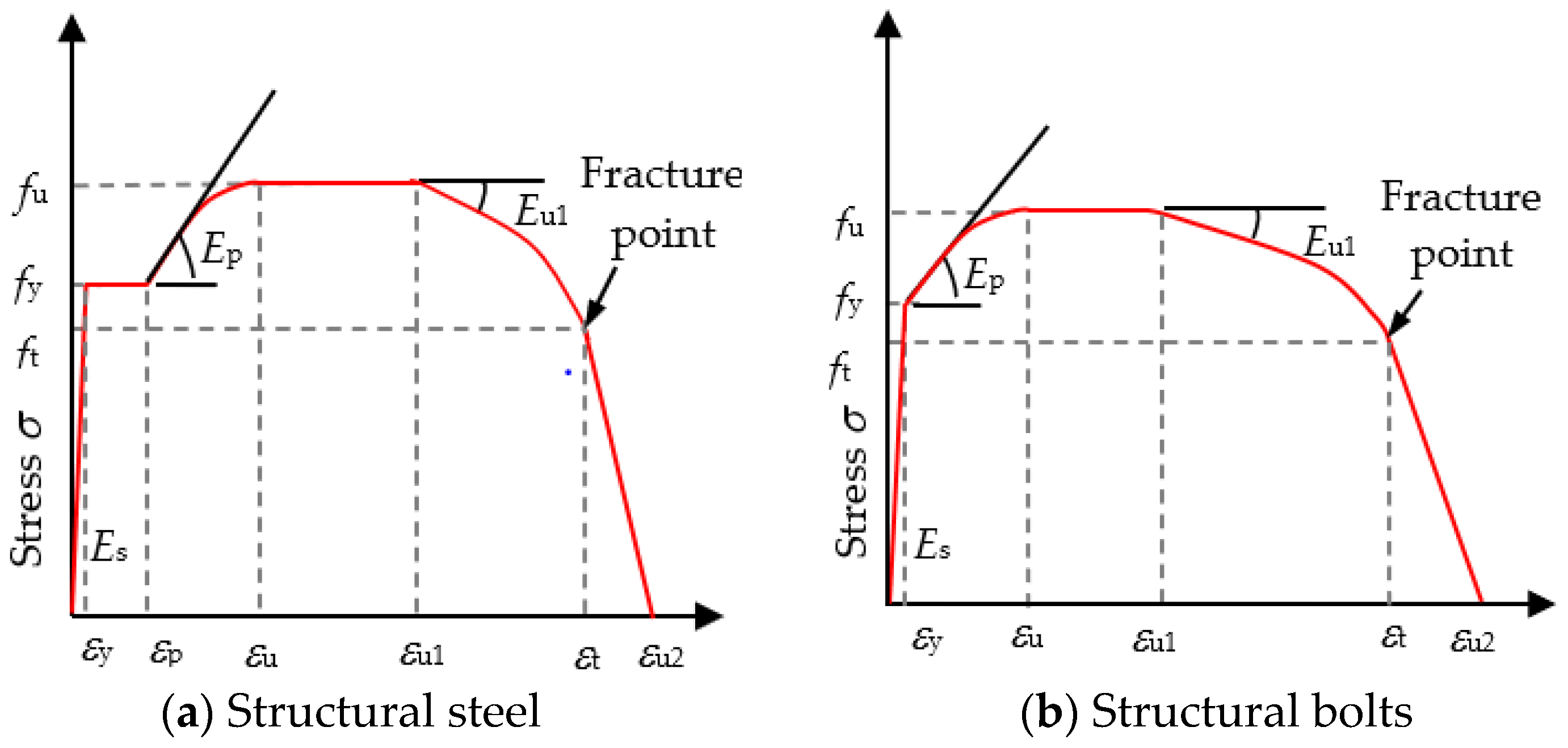
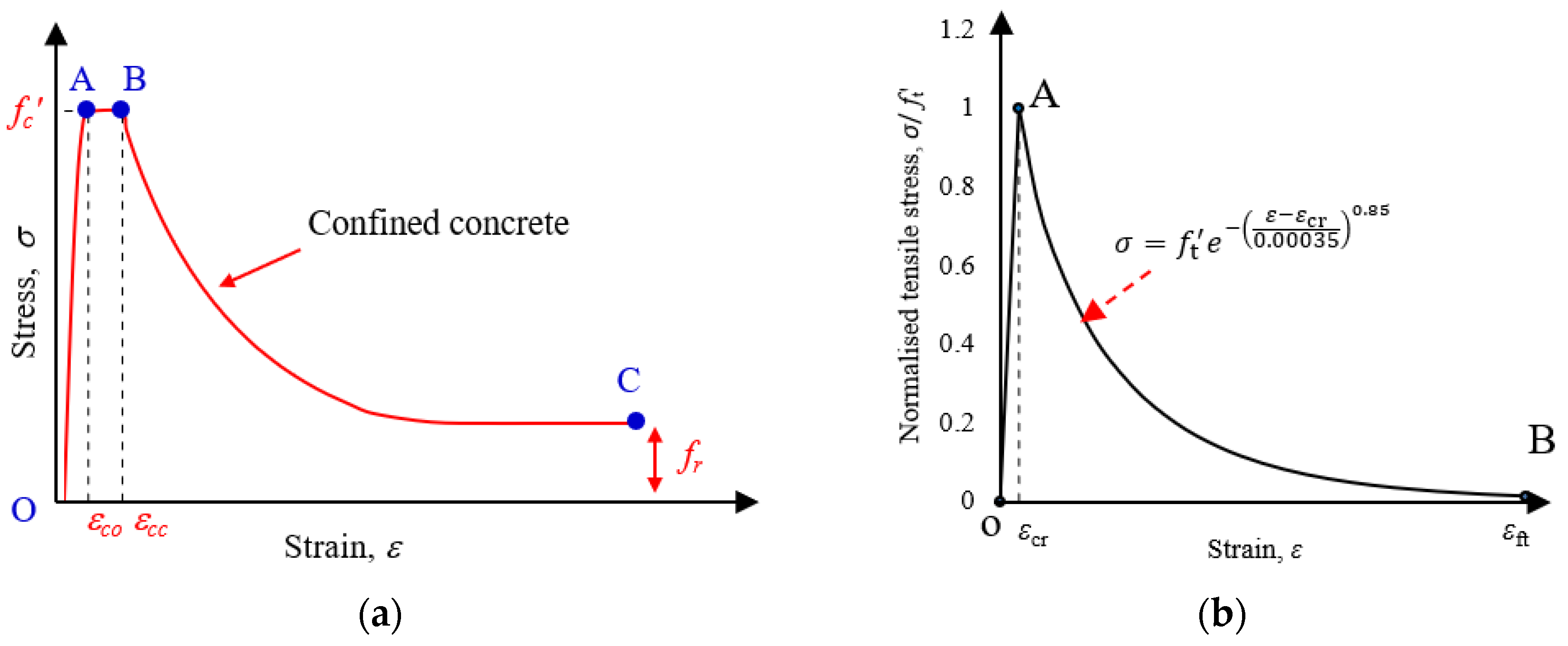
3.2. Stress–Strain Material Models Used in FE Modelling

A linearly elastic-perfectly plastic stress–strain model is generally used to simulate steel tubes of square CFST columns under compression [2]. In this paper, a linearly elastic–plastic stress–strain model with strain hardening and softening [61] is used for the steel tube of square CFST columns under tension. The full-range stress–strain models for structural steels and bolts, as per Hassan [61], are used in this study to simulate the strain hardening and softening material behaviour of structural steel and structural bolt materials. It is worth mentioning that when steel materials are under tension and bending, strain hardening behaviour is observed. Due to this, strain hardening behaviour is considered in the stress–strain material models of bolts and steel plates used in prefabricated CFST columns with BCC connections. A typical full-range stress–strain curve used in FE modelling is given in Figure 4a and Equation (1) for structural steels (steel tube, base plate, and stiffener) and in Figure 4b and Equation (2) for structural bolts.
σ = { E s   ε                      0 ε < ε y f y                       ε y ε < ε p f u ( f u f y ) ( ε u ε ε u ε p ) p             ε p ε < ε u f u                      ε u ε < ε u 1 f u ( f u f t ) ( ε ε u 1 ε t ε u 1 ) p             ε u 1 ε < ε t f t f t ( ε ε t ε u ε t )                ε t ε ε u 1
σ = { E s   ε                         0 ε < ε y f u ( f u f y ) ( ε u ε ε u ε y ) p                 ε y ε < ε u f u                           ε u ε < ε u 1 f u ( f u f t ) ( ε ε u 1 ε t ε u 1 ) p                ε u 1 ε < ε t f t f t   ( ε ε t ε u 2 ε t )                     ε t ε ε u 2
where σ and ε are engineering stress and strain, respectively, ε y is the yield strain ( ε y = f y / E s ), ε p is the strain at the onset of strain hardening, ε u is the strain at ultimate strength f u ; ε u 1   is the strain at the onset of strain-softening; ε t is the strain at fracture stress f t ; ε u 2 is the total strain; p is the strain-hardening exponent; and p is the strain-softening exponent. The calculation details of the value of ε u ,   ε u 1 ε t ,   ε u 2 , p , p and f t   are discussed in [61].
In this study, the elastic and plastic behaviour of concrete materials is considered. To simulate the elastic behaviour of concrete, the modulus of elasticity of unconfined concrete is used. To simulate the plastic behaviour, the stress–strain model of confined concrete is used.
The elastic modulus used in FE modelling of core concrete is determined as per the recommendation in ACI 318 [62] using Equation (3).
E c = 4700 f c
where f c is the compressive strength of unconfined concrete in MPa.
Different studies [50,51,52,53,54,63,64,65,66,67,68] developed different stress–strain models for confined concrete by considering the effect of confinement and stress-path dependence. These material models were developed based on the research conducted on concrete confined by steel tube [50,51,52,53,54,67] or fibre-reinforced polymer (FRP) [63,64,65,66,68]. The confining stress was considered in the stress-path history of confinement provided by steel tube or FRP [54,66]. Although there are different materials for confined concrete, the stress–strain model proposed by Tao et al. [54] for confined concrete under compression is used in this study to simulate the behaviour of concrete confined by steel tube in CFST columns, as this model has been widely used in the literature. The stress–strain model used in the FE modelling of confined concrete is shown in Figure 5a for compression and Figure 5b for tension. The details of the full-range stress–strain model for compression and tension are available in Tao et al. [54] and Hassan [61], respectively. It is well documented that when CFST columns are under axial compression, there is no or negligible interaction between the steel tube and concrete in the initial loading stage, as a small gap exists between the steel tube and concrete due to the differences in the Poisson’s ratio of the steel tube and concrete [54]. The interaction between steel tube and concrete starts when axial strain increases, as the lateral expansion of the concrete gradually becomes greater than the expansion of the steel until the two components are in contact. This confining stress has been considered in Tao et al. [54] model, and any strength increase in concrete due to the confinement has been captured in the FE modelling through the interaction between the steel tube and concrete.

3.3. Load and Boundary Conditions

The tensile load and boundary conditions are assigned to reflect the actual conditions of PCFST columns with developed BCC connections. Before applying the tensile force, bolt tightening force is applied in the first step, similar to the method reported in Ref. [69], through the “bolt load” option available in ABAQUS [48], and then tensile force is assigned in the second step using the displacement control method at the bottom end of PCFST column. The boundary condition is applied at the top end of PCFST columns and is restrained in the movement (UX, UY, and UZ) and rotation (RX, RX, and RY and RZ) in all directions at the top end of columns, see Figure 3a A “dynamic implicit” approach is used to carry out the nonlinear analysis and to capture the post-peak behaviour when complex interactions among different components are considered in the BCC connection zone [2]. The default convergence criteria and threshold in Abaqus have been used in the FE modelling.

3.4. FE Model Validation

3.4.1. CFST Columns under Tension

Three test data of square CFST columns under tension conducted by Zhou et al. [31] are collected to verify the FE model. The material and geometry properties of three square CFST columns (SCFT ST200-6, SCFT ST200-3, and SCFT ST100-3) collected from Zhou et al. [31] are presented in Table 2. The stress–strain curves of the confined concrete used in FE modelling of SCFT ST200-6, SCFT ST200-3, and SCFT ST100-3 specimens are determined according to Tao et al. [53], based on the unconfined concrete compressive strength reported in Zhou et al. [31]. The stress–strain curves of the steel tube used in the FE modelling are determined according to Hassan [61]. The yield strength of the steel tube is 389.3 MPa, and the unconfined concrete compressive strength is 43.3 MPa. The element type, mesh size and contact between steel and concrete are discussed in Section 3.1, Section 3.2, Section 3.3.
The results of the FE model and test of SCFT ST200-6, SCFT ST200-3, and SCFT ST100-3 specimens are shown in Figure 6. It can be observed from Figure 6 that the initial stiffnesses of the specimens obtained from FE models are observed to be the same as their experimental results. It can also be observed that the FE predicted ultimate tensile strengths of SCFT ST200-6, SCFT ST200-3, and SCFT ST100-3 specimens are matched to their test results. In this paper, the FE predicted ultimate tensile strength of each square CFST column under tension is determined based on the load at 0.01 strain, which is selected based on the definition used for the ultimate capacity of CFST columns under compression [53] when there is a strain hardening behaviour and does not have any softening branch on the load-strain curve. This definition is well established and accepted by researchers. The FE predicted ultimate tensile strength capacities of SCFT ST200-6, SCFT ST200-3, and SCFT ST100-3 columns are 2064.45 kN, 1080.50 kN, and 508.68 kN, respectively. The tested ultimate tensile strengths of SCFT ST200-6, SCFT ST200-3, and SCFT ST100-3 columns are 2003.53 kN, 1035.30 kN, and 504.50 kN, respectively. The maximum prediction error is 4.3%. As the predicted FE tensile results match reasonably with the experimental results reported in [31], the verified FE model is considered for the numerical analysis of square PCFST columns with developed BCC connections.

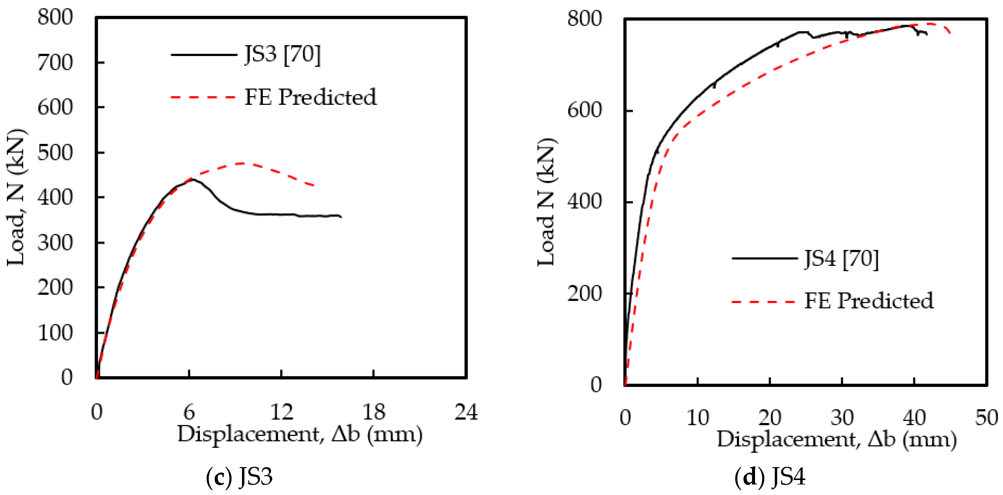
3.4.2. Bolted T-Stub Connections under Tension

As there are no test data available on the proposed PCFST columns with BCC connections under tension, test data of T-stub connections (i.e., CFST columns joints with bolt connection under tension) are considered in this study for the validation of the developed FE model. Furthermore, the behaviour of T-stub connections under tension is similar to the behaviour of proposed PCFST columns with BCC connections under tension. Four specimens (JS1, JS2, JS3 and JC4) under tension tested by Li et al. [70] were simulated, which included the endplate (280 × 200 × 14), blind bolts (M20 Grade 8.8) and binding bars ( ϕ 16 ). Four binding bars were used in specimen JS2, and eight binding bars were used in specimen JS3. One of the CFST column joints used passing through bolts ( ϕ 20 ) was introduced as a passing through-bolted ( ϕ 20 ) endplate connection (specimen JS4). The test and FE model results of specimens JS1, JS2, JS3, and JC4 are reported in Figure 7. Failure modes obtained from the test and FE model are illustrated in Figure 8. The load–displacement behaviours obtained from the FE model of each specimen are matched very well with the experimental results of each specimen. The maximum prediction error is 7.99% for specimen JS3. Furthermore, the predicted failure mode of JS3 is similar to the test results. It indicates that the developed FE model can be used to conduct parametric analysis for PCFST columns with developed BCC connections.

3.5. Parametric Study

A parametric study has been conducted to investigate the behaviour of PCFST columns with developed BCC connections. In the parametric analysis, the effect of bolt arrangements (total bolts (TB) = 4, 6, 7, 8), base plate thickness (tbp = 8, 10, 14, and 18 mm), bolt diameters (db = 16, 18, 20, 24 mm), vertical stiffeners (ths = 4, 6, 8, 10 mm), horizontal stiffeners (ths = 10, 12, 13, 15 mm), and yield strength of steel tube (fy,t = 380, 450, and 550 MPa) are mainly investigated. It is worth mentioning that the compressive strength of concrete (50 MPa), width-to-thickness ratio (B/t = 38.5) of the steel tube, and maximum outer dimension (154 mm) of the steel tube are kept constant. The results obtained from the FE analysis based on the above limits of each parameter are discussed in Section 4.

4. Results and Discussion

4.1. Effect of Bolts Arrangements

The tensile behaviour of four PCFST columns with different bolts arrangement has been investigated in this section, as shown in Figure 9a–d. In this section, a total of eight full-scale FE models for PCFST columns (154 × 154 × 4 mm) with BCC connections are simulated under tensile loading for different numbers of tensile bolts (TB = 4, 6, 7, 8), and base plate thicknesses (tbp = 8 mm and 18 mm). The dimension (B × t) of the steel tube of eight square PCFST column is 154 × 4 mm.
The tensile load–elongation curves of PCFST columns with developed BCC connections are reported in Figure 10a for tbp = 8 mm and in Figure 10b for tbp = 18 mm. In both cases (tbp = 8 mm and 18 mm), the thickness of steel tube (t = 4 mm), horizontal stiffeners (ths = 13 mm), vertical stiffeners (tvs = 8 mm), the diameter of bolts (db = 20 mm) and length of column (L = 550 mm) are kept the same. The material properties of base plate (fy,bp = 388 MPa), stiffeners (fy,s = 388 MPa), bolts (fy,b = 640 MPa), steel tube (fy,t = 379 MPa), and concrete ( f c = 50 MPa) are kept the same. The elastic modulus, yield strength, and ultimate tensile strength of steel tubes, base plates, stiffeners, and bolts are reported in Table 1. The tensile load–elongation curves of PCFST columns with developed BCC connections vary with the number of bolts, as shown in Figure 10a,b. When the thickness of the base plate tbp = 8 mm in the developed BCC connections, the initial stiffness of the PCFST column with developed BCC connections changes with the number of bolts, as shown in Figure 10a. The higher stiffness is observed for the BCC connections with eight bolts, and the lower stiffness is observed for the BCC connections with four bolts. The ultimate tensile load capacity of PCFST columns is observed to be 550.70 kN, 734.11 kN, 831.03 kN, and 929.71 kN, respectively, for BCC connections with four, six, seven, and eight bolts, as shown in Figure 10a. The tensile load capacity improves significantly when a larger number of bolts are used in the BCC connection to connect two PCFST columns. Compared to the four bolts BCC connection, the maximum load improvement is 33.30% for six bolts BCC connection, 50.90% for seven bolts BCC connection, and 68.82% for eight bolts BCC connections. In all cases, the failure is due to the failure of bolts and the yielding of the base plate.
When an 18 mm thick base plate is used in BCC connections, the ultimate tensile load capacity is observed to be 892.34 kN, 971.58 kN, 1101.93 kN, 1106.61 kN, respectively, for the BCC connections with four, six, seven, and eight bolts. The maximum load increase for eight bolts BCC connections is 24% compared to the four bolts BCC connections. However, the tensile load capacities of the columns for seven and eight bolts BCC connections are almost the same. This is due to the failure of the base plate. Therefore, the tensile load capacity of PCFST columns with 18 mm base plate BCC connections is higher than that of the PCFST columns with 8 mm base plate BCC connections, as shown in Figure 11.

4.2. Effect of the Thickness of Base Plate

The base plate is one of the most important parameters of the developed connection. The effects of the base plate on the tensile load capacity of the PCFST column with connections are studied in this section by changing the thickness of the base plate (tbp = 8, 10, 14, and 18 mm). The effect of base plate thickness is also investigated by incorporating different numbers of tensile bolts (TB = 4, 6, 7, 8) in BCC connections. The tensile load–elongation curves of PCFST columns for different base plate thicknesses (tbp = 8–18 mm) are shown in Figure 12a–d for the different numbers of bolts. In all cases, the thickness of the steel tube (t = 4 mm), horizontal stiffeners (ths = 13 mm), vertical stiffeners (tvs = 8 mm), bolt diameter (db = 20 mm) and length of the column (L = 550 mm) are kept the same. Even the material properties of base plate (fy,bp = 388 MPa), stiffeners (fy,s = 388 MPa), bolts (fy,b = 640 MPa), steel tube (fy,t = 379 MPa), and concrete ( f c = 50 MPa) are considered the same.
The tensile load–elongation curves of PCFST columns with four bolted BCC connections with different base plate thicknesses are reported in Figure 12a–d show the tensile load–elongation curves of PCFST columns for four bolted BCC connections, six bolted BCC connections, seven bolted BCC connections, and eight bolted BCC connections. When the thickness of the base plate is changed from 8 mm to 18 mm, the initial stiffness of the PCFST column changes for all cases, as shown in Figure 12a–d. The higher initial stiffness is observed for 18 mm base plate BCC connections, and the lower stiffness is observed for 8 mm base plate BCC connections. The ultimate tensile load capacity of PCFST columns improves significantly with an increase in the thickness of the base plate for four bolted BCC connections (Figure 12a) and six bolted BCC connections (Figure 12b). However, the ultimate capacity of PCFST columns with seven or eight bolted BCC connections is observed to be almost the same for 14 mm and 18 mm thick base plates. The failure mode of PCFST columns with BCC connections mainly depends on the number of bolts and thickness of the base plate. The failure is observed on the base plates and bolts when thinner base plates (<10 mm) are used in BCC connections with 4–8 bolts. When thicker base plates (≥10 mm) are used, failure is observed due to the combined failure of the steel tubes, base plates, stiffeners, and bolts.

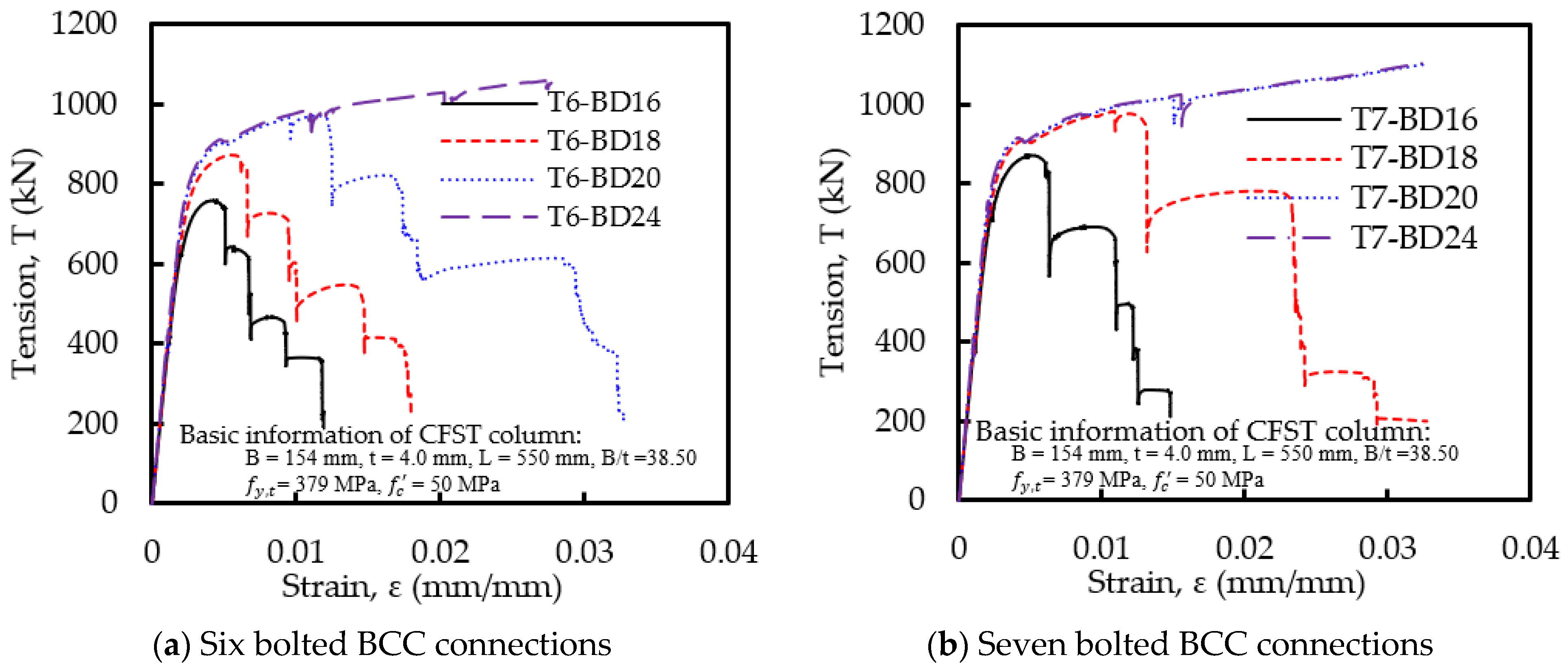
4.3. Effect of Bolt Diameter

The effects of bolts diameter are analysed in this section by changing the diameter of bolts, while the other connecting parameters (vertical stiffeners = 8 mm, horizontal stiffeners =13 mm, base plate = 18 mm) of BCC connections are kept the same. The concrete compressive strength and yield strength of steel tube and connecting components of developed BCC connections used in FE modelling are reported in Table 1 and in Section 4.1. Figure 13 describes the tensile load–elongation behaviour of PCFST columns with different diameters of bolts (db = 16, 18, 20, 24 mm) used in BCC connections. The results of the six bolted BCC connections s are described in Figure 13a. Figure 13b,c show the tensile load–elongation curves of PCFST columns for seven bolted connections and eight bolted connections, respectively. For six bolted connections, the ultimate tensile load capacity of PCFST columns increases significantly with an increase in the diameter of bolts, as shown in Figure 13a. Even the failure mode also changes from the failure of bolts to the combined failure of steel tubes, base plates, and bolts. For seven bolted connections, there is no significant change in the ultimate tensile load capacity of PCFST columns when the bolt diameter is considered 20 mm or higher, as shown in Figure 13b. In this case, the failure is also observed to be the combined failure, i.e., yielding of steel tube, base plate, stiffeners, and bolts. However, the load capacity is reduced when a 16 or 18 mm diameter of bolts is used. Even the failure is observed to be due to the failure of bolts. For eight bolted BCC connections, the ultimate tensile load capacity of PCFST columns is found to be the same, although the diameter of the bolts is increased from 16 mm to 24 mm. In all cases, the failure is also observed to be the combined failure (yielding of steel tube, base plate, and bolts). It can be noted that the smaller diameter (16 mm) bolts can be used for eight bolted BCC connections, whereas 20 mm and 24 mm diameter bolts (larger bolts) can be used for seven bolted BCC connections and six bolted BCC connections, respectively, to achieve the same tensile load capacity.

4.4. Effect of Vertical Stiffener

Four different thicknesses of vertical stiffeners (ths = 4, 6, 8, 10 mm) of BCC connections with six bolts are considered to investigate their effect on the tensile load capacity of PCFST columns. The thickness of horizontal stiffeners (ths = 13mm), base plate (tbp = 18 mm), and steel tube (t = 4 mm) are kept constant in this analysis. The diameter of bolts is used as db = 20 mm. The material properties of the column components, including connecting components of developed BCC connections (base plates, horizontal and vertical stiffeners, bolts), are also kept constant.
Figure 14 shows the tensile load–elongation curves of PCFST columns for different base plate thicknesses used in connections. It can be noted that the initial stiffness of the column is almost the same for all cases, although the value of ths is varied from 4 to 10 mm. However, the yield and ultimate tensile load of the columns are increased. When 4 mm thick vertical stiffeners are used in eight bolted BCC connections, the tensile load of the PCFST column is reduced compared to the same column with 10 mm vertical stiffeners. The failure of the prefabricated column is due to the yielding of 4 mm vertical stiffeners. When the thickness of vertical stiffeners is 8 mm or above, the failure of the column is due to the combined failure of the steel tube, base plate, stiffeners, and bolts.

4.5. Effect of Horizontal Stiffener

Similar to the vertical stiffeners, four different thicknesses (ths = 10, 12, 13, 15 mm) of horizontal stiffeners of BCC connections are considered to investigate their effects on the tensile load capacity of PCFST columns. The other connecting components such as vertical stiffeners (tvs = 8 mm), base plate (tbp = 18 mm), steel tube (t = 4 mm) and bolt (db = 20 mm) and material mechanical properties of column components and connecting components of connections are kept the same. The yield strength of all steel materials and concrete compressive strength are reported in Table 1.
Figure 15 illustrates the effect of horizontal stiffeners on the tensile load–elongation behaviour of PCFST columns with eight bolted BCC connections. In all cases, the tensile load–elongation curves of columns are observed to be almost the same as before the yielding. Only the tensile load capacity at the yielding stage differs. The tensile load capacity for 10 mm and 12 mm thick horizontal stiffeners is lower than that for 13 mm and 15 mm horizontal stiffeners. However, there is no significant effect on the ultimate tensile load due to changing the thickness of horizontal stiffeners from 10 mm to 15 mm. Therefore, it can be concluded from the overall behaviour that the 13 mm thick horizontal stiffener can be considered as the optimal thickness for horizontal stiffeners.

4.6. Effect of Yield Strength of Steel Tube

The influence of connecting components of BCC connections (base plate, vertical stiffeners, horizontal stiffeners, and bolts) is investigated in the previous sections. In this section, the behaviour of eight bolted BCC connections is investigated by varying the yield strengths (fy,t) of hollow steel tubes of (fy,t = 380, 450, and 550 MPa) where the connecting components of eight bolted BCC connections (base plates: tbp = 18 mm, vertical stiffeners: tvs = 8 mm, horizontal stiffeners: ths = 13 mm, and bolts: db = 24 mm) are kept constant. The yield strength of all connecting components except bolts is considered the same as the value of fy,t. The concrete compressive strength and yield strength of bolts are used as 50 MPa and 640 MPa, respectively, for all cases.
The effect of fy,t of steel tube on the tensile load–elongation curves of PCFST columns with eight BCC connections are shown in Figure 16. The initial stiffness of all PCFST columns is observed to be the same, although different fy,t of steel tube is considered. This is well expected as the modulus of elasticity of steel tube, and connecting components are used the same for all cases. However, the ultimate tensile load capacity of columns increases with an increase in the value of fy,t of steel tubes. It means that the tensile behaviour of prefabricated columns depends not only on the connecting components of BCC connections but also on the steel tube. In all cases, the failure is observed due to the value of fy,t of the steel tube, base plate, and bolts.

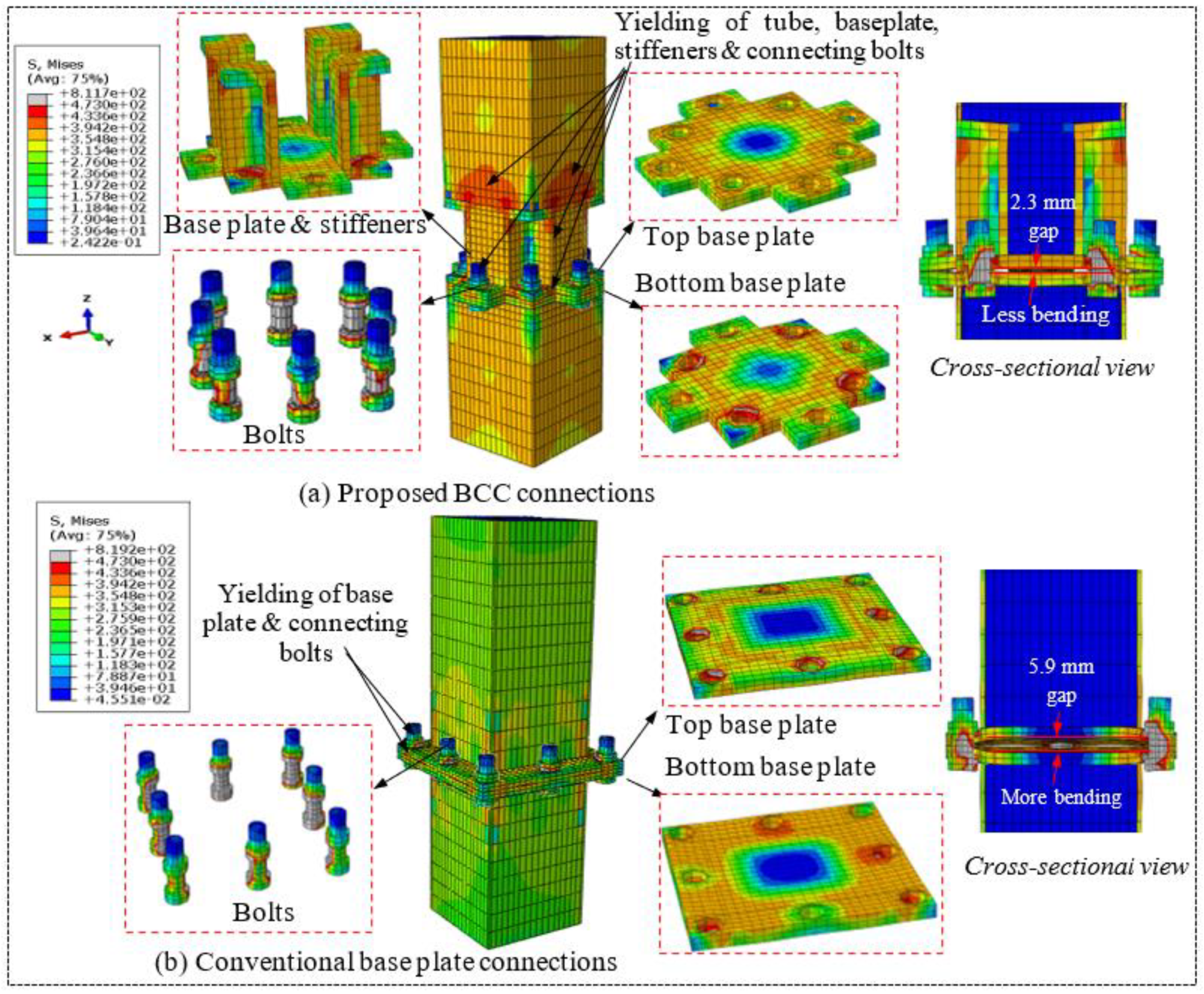
4.7. Comparison with Conventional Base Plate Connections

The behaviour of PCFST columns with developed BCC connections is compared with the same column with conventional base plate connections, as shown in Figure 17. In both cases, a total of eight bolts (db = 20 mm) are used to connect one base to another one. Three different base plate thicknesses (tbp = 10, 14, 18 mm) are considered in both cases for the parametric analysis to evaluate differences in their behaviours. As reported in Section 4.1, the material properties are kept constant for both cases. In the parametric analysis of prefabricated columns with developed BCC connections, the connecting components of BCC connections such as vertical stiffeners (tvs = 8 mm), horizontal stiffeners (ths = 13 mm), steel tube (t = 4 mm) and bolt (db = 20 mm) are kept constant.
Figure 18 shows the tensile load–elongation curves of PCFST columns with developed BCC connections and conventional connections. Figure 18a reports the tensile behaviour for the 10 mm base plate used in the BCC connections and conventional connections. Figure 18b,c shows the tensile load–elongation curves of PCFST columns for the 14 mm base plate and 18 mm base plate, respectively. It can be noted from Figure 18a–c that the tensile behaviour of PCFST columns with conventional base plate connections is different from that of PCFST columns with developed BCC connections.
It can be seen that for a thinner base plate (10 mm), the initial stiffness and ultimate tensile load capacity of columns with conventional connections are lower than those of the columns with developed BCC connections, as shown in Figure 18a. However, the initial stiffness and tensile load capacity of the column for conventional connections increases with an increase in the thickness of the base plate, as shown in Figure 18b,c. It is clear that thicker base plates are required for conventional base plate connections to achieve the higher tensile load capacity of the PCFST column. Although the tensile load–elongation behaviour of columns with conventional connections mainly depends on the thickness of the base plate, the tensile load–elongation behaviour of PCFST columns with developed BCC connections is not influenced significantly by the thickness of the base plate. This could be due to the more prying action developed on the conventional base plate connections [43] compared to the developed BCC connections under tension. However, there is no difference in the compression capacity of prefabricated CFST columns with conventional base plate connections and the developed BCC connections under compression.
For example, in conventional base plate connections, the base plate (tbp = 10 mm), as shown in Figure 19b, is mainly subjected to a larger bending deformation compared to the base plate of developed BCC connections having a 10 mm base plate, as shown in Figure 19a. It can be seen that the maximum gap between two base plates of prefabricated CFST columns is observed for conventional connections (5.9 mm), which can be minimised by around 61% by using proposed BCC connections. This benefit can be achieved by proper bolt arrangements, i.e., the location of the bolts. For developed BCC connections, four bolts are used at four corners, which help to mitigate the bending deformation introduced at the corner of the base plate, as shown in Figure 19a. In order to demonstrate this further, the stress vector symbol is used to understand the internal stress distribution of base plates, bolts and steel tubes.
Both types of connections are studied, as shown in Figure 20a for BCC connections and Figure 20b for connectional connections. The maximum tensile and compressive stresses (S, SS) are shown in red and blue colours, respectively. The magnitude of the tensile and compressive stresses is represented by the length of the vector symbol. It can be seen from Figure 20a,b that the maximum tensile (374.6 MPa) and compressive stresses (705.1 MPa) are observed on the base plate of conventional connections and are higher than the maximum tensile stresses (321.1 MPa) and compressive stresses (508.1 MPa) of BCC connections, respectively. It is worth mentioning that the stresses are determined at the strain of 0.01 of the steel tube. It means that the failure occurred early on the conventional base plate connection at a lower load capacity compared to the BCC connections at the same tensile strain of the steel tube.

5. Design Calculations for Axial Tension

5.1. Design Requirement According to AS1170 and AS5100

When steel tubes are infilled with concrete to make PCFST columns, the tensile load capacity of such columns increases compared to the hollow steel tube [28]. Although the tensile load capacity of the PCFST column is increased compared to the tensile load capacity of hollow steel tubes [28], the contribution of the steel tube is mainly considered in the design tensile load capacity of CFST columns [45]. The design tensile load capacity of the PCFST column is recommended as T c = 0.9   f y t A s t in the Australian Standard AS5100 [46], where A s t is the cross-sectional area of steel tube and f y t is the yield stress of steel tube. In AS1170 [47], the design tensile load capacity of PCFST columns based on the robustness consideration is recommended as T c = η N c , where N c represents the ultimate axial compressive strength of PCFST column and η reflects the factor which accounts for the accidental damage. Li et al. [45] recommended the value of η to be 0.5. It means that the design tensile load capacity of PCFST column with column-column connection should be at least half of the ultimate compressive strength ( N c ) of PCFST column without column-column connections. The ultimate compressive capacity of square PCFST column can be determined using N c = f y t A s t + f c A c   as per recommendation of the Australian Standard AS5100 [46], where A c is the cross-sectional area of concrete and f c is the compressive strength of concrete core of PCFST column.

5.2. Evaluation of PCFST Columns Design Equations

The tensile strength capacity of PCFST columns with developed BCC connections is compared with robustness and design strength equations, as shown in Figure 21. It can be seen from Figure 21a that the ultimate tensile load capacity of the PCFST column with developed connections is higher compared to the design capacity calculated according to the AS5100 [46] and AS1170 [47]. It means that the tensile strength of the PCFST columns with developed BCC connections can satisfy the design requirements of AS5100 [46] and the robustness requirement of AS1170 [47].
When the confinement factor, ξ c = A s t f y , t A c f c < 1 , as shown in Figure 21a, the design tensile strength capacity of the PCFST column calculated based on the robustness requirement of AS1170 [47] is higher than that of the value determined according to AS5100. However, it is the opposite for ξ c > 1 , as shown in Figure 21c. When the confinement factor, ξ c 1 , as shown in Figure 21b, the design tensile strength capacity of the PCFST column calculated based on the robustness requirement of AS1170 [47] is almost equal to the tensile strength capacity determined according to AS5100 [46]. It can be observed from the analysed results that AS5100 [46] is more conservative for lower confinement factors ( ξ c < 1 ) and AS1170 [47] is more conservative for higher confinement factors ( ξ c > 1 ). Therefore, the design tensile strength capacity of PCFST columns with developed connections should satisfy both the design requirements of AS5100 [46] and the robustness requirement of AS1170 [47].

5.3. Design Recommendations for BCC Connections

As the design tensile strength of the PCFST columns with BCC connections mainly depends on bolts and base plates, the tension capacity of the bolts and bending capacity of the base plate should be higher than the tensile capacity of the steel tube. In order to ensure this, the diameter and base plate thickness should be determined based on the yield strength of the steel tube according to the following recommendation. The main implication of this design recommendation research is that the proposed theoretical design recommendation will help the practicing structural engineers.
(1) The bolt diameter can be determined based on the assumption that the total tensile capacity of bolts is equal to the total tensile capacity of the steel tube. The total tensile capacity ( T b = N A b f p , b ) of bolts mainly depends on the total number (N) of bolts used in BCC connections and the proof strength of the bolt ( f p , b = 0.85 f y , b ), where f y , b is the yield strength of the bolt, A b ( =   π 4 d b 2 ) is the cross-sectional area of a bolt and d b is the diameter of the bolt. The total tensile capacity ( T t = A s t   f y , t ) of steel tube depends on the cross-sectional area ( A s t ) of steel tube and the yield stress ( f y , t ) of steel tube. From equilibrium, T b   is equal to T t , as shown in Figure 22. It means that N A b f p , b = A s t   f y , t or N   π 4 d b 2 f p , b = A s t   f y , t After simplification, the diameter of the bolt ( d b ) can be determined as of d b =   4 A s t   f y , t   π   N f p , b .
(2) The plate thickness can be designed according to the yielding limit state at the tension interface [71]. The bending moment of the plate per unit length due to the generated bolt tensile force can be determined as M b p = T b 1 l b b p , where T b 1 ( = A b f p , b ) is the tensile force subjected to one corner bolt, l is the critical base plate cantilever dimension from the centre of the bolt to the steel tube, b b p is the width of the base plate, as shown in Figure 22. M b p can also be calculated from the thickness of the base plate ( t b p ) and the yield stress of the base plate ( f y , b p ) as M b p = f y , b p t b p 2 By simplifying these two relationships, M b p can be rewritten as M b p = f y , b p t b p 2 = A b f p , b l b b p . Further simplifying this relationship, the minimum required thickness of the base plate ( t b p ) can be determined as t b p =   A b f p , b l b b p f y , b p .

6. Conclusions

Prefabricated column-column connections are designed for corner columns, edge columns and interior columns to connect two PCFST columns. The tensile load–elongation behaviour of PCFST columns with developed BCC connections is studied numerically. The tensile strength capacity of PCFST columns with developed BCC connections mainly depends on the number of bolts and the configuration of base plates. Six bolted BCC connections can be used for the corner column, whereas seven bolted BCC connections can be used for an edge column, and eight bolted BCC connections can be used for an interior column. The tensile load capacity of PCFST columns with six bolted BCC connections is slightly lower than that of seven and eight bolted BCC connections. The tensile behaviour of PCFST columns with eight bolted BCC connections is compared against the same column with the conventional base plate connections with eight bolts. The initial stiffness and ultimate tensile load capacity of PCFST columns with developed BCC connections are higher than that of the corresponding columns with conventional base plate connections. The thicker base plates are required for conventional base plate connections to connect two PCFST columns, compared to developed BCC connections. It means that the material cost of BCC connections can be minimised compared to the cost of conventional base plate connections. The tensile strength capacity of PCFST columns with developed connections is also compared with the design requirements of AS5100 [46] and the robustness requirement of AS 1170 [38]. The tensile strength of the PCFST columns with developed BCC connections can satisfy both the design requirement of AS5100 [46] and the robustness requirement of AS1170 [47]. The design recommendation is provided to determine the diameter of bolts and thickness of base plates.
The numerical results presented in this paper suggest a few important theoretical and practical implications of this study for future research. First, the theoretical implication of this study is that the design tensile strength capacity of PCFST columns with developed connections needs to check both the design requirements of AS5100 [46] and the robustness requirement of AS1170 [47] as more conservative results are observed in AS5100 [46] for lower confinement factors and AS1170 [47] for higher confinement factors. Second, the practical implication of this study is that the proposed design recommendation for bolts and plates will guide practising structural engineers to design the connection components of prefabricated CFST columns.
The limitation of this study is that only finite element analysis is used to investigate the behaviour of the CFST columns with developed BCC connections under tension, not an experimental study. Therefore, further experimental studies are required to examine the behaviour of proposed connections by considering different parameters to develop the design guidelines for the design capacity and construction procedures for prefabricated CFST columns with BCC connections under tensions. In addition, the stiffness and ultimate capacity of PCFST columns with BCC connection under bending can be investigated in future research studies. Further research can be performed to determine the design capacity of prefabricated columns with proper safety factors.

Author Contributions

Methodology, M.K.H.; Investigation, M.K.H.; Resources, M.K.H.; Data curation, M.K.H.; Writing—original draft, M.K.H.; Writing—review & editing, S.S. and P.R. All authors have read and agreed to the published version of the manuscript.

Funding

This research received no external funding.

Institutional Review Board Statement

Not applicable.

Informed Consent Statement

Not applicable.

Data Availability Statement

Not applicable.

Acknowledgments

The authors would like to acknowledge the support provided by Western Sydney University for finite element modelling works and greatly appreciate for providing the research facilities.

Conflicts of Interest

The authors declare no conflict of interest.

References

  1. Hassan, M.K.; Tao, Z.; Liao, L. Numerical study of column-column connections for prefabricated concrete-filled steel columns. In Proceedings of the 25th Australasian Conference on Mechanics of Structures and Materials (ACMSM25), Brisbane, Australia, 4–7 December 2018. [Google Scholar]
  2. Hassan, M.K.; Sheikh, N.; Saha, S. Behaviour and design of prefabricated CFST stub columns with PCC connections under compression. Thin-Walled Struct. 2021, 166, 108041. [Google Scholar] [CrossRef]
  3. Tomii, M.; Yoshimura, K.; Morishita, Y. Experimental studies on concrete filled steel tubular stub columns under concentric loading. In Proceedings of the International Colloquium on Stability of Structures under Static and Dynamic Loads, Washington, DC, USA, 17–19 May 1977. [Google Scholar]
  4. Yamamoto, T.; Kawaguchi, J.; Shosuke, M. Experimental study of scale effects on the compressive behavior of short concrete-filled steel tube columns. In Proceedings of the United Engineering Foundation Conference on Composite Construction in Steel and Concrete IV (AICE), Banff, AL, Canada, 28 May–2 June 2000; Volume 4, pp. 879–891. [Google Scholar]
  5. Uy, B. Strength of short concrete filled high strength steel box columns. J. Constr. Steel Res. 2001, 57, 113–134. [Google Scholar] [CrossRef]
  6. Huang, C.S.; Yeh, Y.K.; Liu, G.Y.; Hu, H.T.; Tsai, K.C.; Weng, Y.T.; Wang, S.H.; Wu, M.-H. Axial load behavior of stiffened concrete-filled steel columns. J. Struct. Eng. 2002, 128, 1222–1230. [Google Scholar] [CrossRef]
  7. Han, L.H. Tests on stub columns of concrete-filled RHS sections. J. Constr. Steelwork 2002, 58, 353–372. [Google Scholar] [CrossRef]
  8. Kitoh, H.; Koyabu, T.; Sahara, K.; Sonoda, K. Concrete filled circular steel tubular studs with a large ratio of diameter to thickness under compression. Doboku Gakkai Ronbunshu 2004, 2004, 25–36. [Google Scholar] [CrossRef] [PubMed]
  9. Sakino, K.; Nakahara, H.; Morino, S.; Nishiyama, I. Behavior of centrally loaded concrete-filled steel-tube short columns. J. Struct. Eng. 2004, 30, 180–188. [Google Scholar] [CrossRef]
  10. Tao, Z.; Han, L.H.; Wang, D.Y. Strength and ductility of stiffened thin-walled hollow steel structural stub columns filled with concrete. Thin-Walled Struct. 2008, 46, 1113–1128. [Google Scholar] [CrossRef]
  11. Tao, Z.; Uy, B.; Han, L.H.; Wang, Z.B. Analysis and design of concrete-filled stiffened thin-walled steel tubular columns under axial compression. Thin-Walled Struct. 2009, 47, 1544–1556. [Google Scholar] [CrossRef]
  12. Tao, Z.; Han, L.H.; Wang, Z.B. Experimental behaviour of stiffened concrete-filled thin-walled hollow steel structural (HSS) stub columns. J. Constr. Steel Res. 2005, 61, 962–983. [Google Scholar] [CrossRef]
  13. Liew, J.Y.R.; Xiong, D.X. Experimental investigation on tubular columns infilled with ultra-high strength concrete. In Proceedings of the 13th International Symposium on Tubular Structures, Hong Kong, UK, 15–17 December 2010; pp. 637–645. [Google Scholar]
  14. Li, D.; Jin, L.; Du, X.; Fu, J.; Lu, A. Size effect tests of normal-strength and high-strength RC columns subjected to axial compressive loading. Eng. Struct. 2016, 109, 43–60. [Google Scholar] [CrossRef]
  15. Zhu, L.; Ma, L.; Bai, Y.; Li, S.; Song, Q.; Wei, Y.; Zhang, L.Y.; Zhang, Z.Y.; Sha, X.C. Large diameter concrete-filled high strength steel tubular stub columns under compression. Thin-Walled Struct. 2016, 108, 12–19. [Google Scholar] [CrossRef]
  16. Liew, J.Y.R.; Xiong, M.; Xiong, D. Design of Concrete filled tubular beam-columns with high strength steel and concrete. Structures 2016, 8, 213–226. [Google Scholar] [CrossRef]
  17. Ekmekyapar, T.; Alwan, O.H.; Hasan, H.G.; Shehab, B.A.; Al-Eliwi, B.J.M. Comparison of classical, double skin and double section CFST stub columns: Experiments and design formulations. J. Constr. Steel Res. 2019, 155, 192–204. [Google Scholar] [CrossRef]
  18. Uy, B. Strength of concrete filled steel box columns incorporating local buckling. J. Struct. Eng. 2000, 126, 341–352. [Google Scholar] [CrossRef]
  19. Elchalakani, M.; Karrech, A.; Hassanein, M.F.; Yang, B. Plastic and yield slenderness limits for circular concrete filled tubes subjected to static pure bending. Thin-Walled Struct. 2019, 109, 50–64. [Google Scholar]
  20. Han, L.H.; Lu, H.; Yao, G.H.; Liao, F.Y. Further study on the flexural behaviour of concrete-filled steel tubes. J. Constr. Steel Res. 2006, 62, 554–565. [Google Scholar] [CrossRef]
  21. Thody, R. Experimental Investigation of the Flexural Properties of High-Strength Concrete-Filled Steel Tubes. Master’s Thesis, University of Washington, Seattle, WA, USA, 2006. [Google Scholar]
  22. Moon, J.; Roeder, C.W.; Lehman, D.E.; Lee, H.E. Analytical modelling of bending of circular concrete-filled steel tubes. Eng. Struct. 2012, 42, 349–361. [Google Scholar] [CrossRef]
  23. Lu, Y.; Liu, Z.Z.; Li, W.J. Behavior of steel fibers reinforced self-stressing and self-compacting concrete-filled steel tube subjected to bending. Constr. Build. Mater. 2017, 156, 639–651. [Google Scholar] [CrossRef]
  24. Xiong, M.X.; Xiong, D.X.; Liew, J.Y.R. Flexural performance of concrete filled tubes with high tensile steel and ultra-high strength concrete. J. Constr. Steel Res. 2017, 132, 191–202. [Google Scholar] [CrossRef]
  25. Li, G.; Liu, D.; Yang, Z.; Zhang, C. Flexural behavior of high strength concrete filled high strength square steel tube. J. Constr. Steel Res. 2017, 128, 732–744. [Google Scholar] [CrossRef]
  26. Abed, F.H.; Abdelmageed, Y.I.; Kerim Ilgun, A. Flexural response of concrete-filled seamless steel tubes. J. Constr. Steel Res. 2018, 149, 53–63. [Google Scholar] [CrossRef]
  27. Al Zand, A.W.; Badaruzzaman, W.H.W.; Al-Shaikhli, M.S.; Ali, M.M. Flexural performance of square concrete-filled steel tube beams stiffened with V-shaped grooves. J. Constr. Steel Res. 2020, 166, 105930. [Google Scholar] [CrossRef]
  28. Han, L.H.; He, S.H.; Liao, F.Y. Performance and calculations of concrete filled steel tubes (CFST) under axial tension. J. Constr. Steel Res. 2011, 67, 1699–1709. [Google Scholar] [CrossRef]
  29. Li, W.; Han, L.H.; Chan, T.M. Numerical investigation on the performance of concrete-filled double-skin steel tubular members under tension. Thin-Walled Struct. 2014, 79, 108–118. [Google Scholar] [CrossRef]
  30. Li, W.; Han, L.H.; Chan, T.M. Performance of Concrete-Filled Steel Tubes subjected to Eccentric Tension. J. Struct. Eng. 2015, 141, 04015049. [Google Scholar] [CrossRef]
  31. Zhou, M.; Fan, J.S.; Tao, M.X.; Nie, M.G. Experimental study on the tensile behavior of square concrete-filled steel tubes. J. Constr. Steel Res. 2016, 121, 202–215. [Google Scholar] [CrossRef]
  32. Xu, L.Y.; Tao, M.X.; Zhou, M. Analytical model and design formulae of circular CFSTs under axial tension. J. Constr. Steel Res. 2017, 133, 214–230. [Google Scholar] [CrossRef]
  33. AIJ. Recommendations for Design and Construction of Concrete Filled Steel Tubular Structures; Architectural Institute of Japan (AIJ): Tokyo, Japan, 2008. [Google Scholar]
  34. AISC 360-05; Specification for Structural Steel Buildings. American Institute of Steel Construction (AISC): Chicago, IL, USA, 2005.
  35. EN 1994-1-2:2005; Eurocode 4. Design of Composite Steel and Concrete Structures-Part1-1: General Rules-Structural Fire Design. European Committee for Standardisation: Brussels, Belgium, 2005.
  36. Zheng, Y.; Guo, Z.; Cao, J. Confinement mechanism and confining stress distribution of new grouting coupler for rebars splicing. J. Harbin Inst. Technol. 2015, 47, 106–111. [Google Scholar]
  37. Zheng, Y.; Guo, Z.; Zhang, X. Effect of sleeve inner cavity structure on bond performance of grouted pipe splice. J. Build. Struct. 2018, 39, 158–166. [Google Scholar]
  38. Sui, L.L.; Fan, S.Y.; Huang, Z.Y.; Zhang, W.; Zhou, Y.; Ye, J.Q. Load transfer mechanism of an unwelded, unbolted, grouted connection for prefabricated square tubular columns under axial loads. Eng. Struct. 2020, 222, 111088. [Google Scholar] [CrossRef]
  39. Huang, Z.Y.; Zhang, W.; Fan, S.Y.; Sui, L.L.; Ye, J.Q. Axial load resistance of a novel UHPFRC grouted SHS tube sleeve connection: Experimental, numerical and theoretical approaches. J. Struct. Eng. 2021, 147, 04021184. [Google Scholar] [CrossRef]
  40. Liu, X.C.; Xu, A.X.; Zhang, A.L.; Ni, Z.; Wang, H.X.; Wu, L. Static and seismic experiment for welded joints in modularised prefabricated steel structure. J. Constr. Steel Res. 2015, 19, 183–195. [Google Scholar] [CrossRef]
  41. Liu, X.; Cui, X.; Yang, Z.; Zhan, X. Analysis of the seismic performance of site-bolted beam to column connections in modularised prefabricated steel structures. Adv. Mater. Sci. Eng. 2017, 2017, 1932730. [Google Scholar] [CrossRef] [Green Version]
  42. Liu, X.C.; Yang, Z.W.; Wang, H.X.; Zhang, A.L.; Pu, S.H.; Chai, S.T.; Wu, L. Seismic performance of H-section beam to HSS column connection in prefabricated structures. J. Constr. Steel Res. 2017, 138, 1–16. [Google Scholar] [CrossRef]
  43. Willibald, S.; Packer, J.A.; Puthli, R.S. Experimental study of bolted HSS flange-plate connections in axial tension. J. Struct. Eng. 2002, 128, 328–336. [Google Scholar] [CrossRef]
  44. Uy, B.; Patel, V.; Li, D.; Aslani, F. Behaviour and design of connections for demountable steel and composite structures. Structures 2017, 9, 1–12. [Google Scholar] [CrossRef]
  45. Li, D.X.; Uy, B.; Aslani, F.; Patel, V. Behaviour and design of demountable CFST column-column connections under tension. J. Constr. Steel Res. 2017, 138, 761–773. [Google Scholar] [CrossRef]
  46. AS5100.6; Bridge Design, Part 6: Steel and Composite Construction. Standards Australia: Sydney, Australia, 2004.
  47. AS1170.4-2007; Earthquake Actions in Australia. Standards Australia: Sydney, Australia, 2007.
  48. ABAQUS. ABAQUS Analysis User’s Guide, Version 2019; Dassault Systèmes Corp.: Providence, RI, USA, 2020. [Google Scholar]
  49. Al-Ani, Y.R. Finite element study to address the axial capacity of the circular concrete-filled steel tubular stub columns. Thin-Walled Struct. 2018, 26, 2–15. [Google Scholar] [CrossRef]
  50. Ellobody, E.; Young, B. Nonlinear analysis of concrete-filled steel SHS and RHS columns. Thin-Walled Struct. 2006, 44, 919–930. [Google Scholar] [CrossRef]
  51. Han, L.H.; Yao, G.H.; Tao, Z. Performance of concrete-filled thin-walled steel tubes under pure torsion. Thin-Walled Struct. 2007, 45, 24–36. [Google Scholar] [CrossRef]
  52. Lin, S.; Zhao, Y.G. Numerical study of the behaviours of axially loaded large-diameter CFT stub columns. J. Constr. Steel Res. 2019, 160, 54–66. [Google Scholar] [CrossRef]
  53. Schneider, S.P. Axially loaded concrete-filled steel tubes. J. Struct. Eng. 1998, 124, 1125–1138. [Google Scholar] [CrossRef]
  54. Tao, Z.; Wang, Z.B.; Yu, Q. Finite element modelling of concrete-filled steel stub columns under axial compression. J. Constr. Steel Res. 2013, 89, 121–131. [Google Scholar] [CrossRef]
  55. Liang, Q.Q. Nonlinear analysis of short concrete-filled steel tubular beam–columns under axial load and biaxial bending. J. Constr. Steel Res. 2008, 64, 295–304, 313–337. [Google Scholar] [CrossRef]
  56. Al-Dujele, R.; Cashell, K.A.; Afshan, S. Flexural behaviour of concrete filled tubular flange girders. J. Constr. Steel Res. 2018, 151, 263–279. [Google Scholar] [CrossRef]
  57. Han, L.H. Flexural behaviour of concrete-filled steel tubes. J. Constr. Steel Res. 2004, 60, 313–337. [Google Scholar] [CrossRef]
  58. Wang, R.; Han, L.H.; Nie, J.G.; Zhao, X.L. Flexural performance of rectangular CFST members. Thin-Walled Struct. 2014, 79, 154–165. [Google Scholar] [CrossRef]
  59. Hassan, M.K.; Tao, Z.; Mirza, O.; Song, T.Y.; Han, L.H. Finite element analysis of steel beam-CFST column joints with blind bolts. In Proceedings of the Australian Structural Engineering Conference (ASEC 2014), Auckland, New Zealand, 9–11 July 2014. [Google Scholar]
  60. Hassan, M.K.; Tao, Z.; Song, T.Y.; Han, L.H. Effects of floor slabs on the structural performance of blind-bolted composite joints. In Proceedings of the 24th Australasian Conference on the Mechanics of Structures and Materials (ACMSM24), Perth, Australia, 6–9 December 2016. [Google Scholar]
  61. Hassan, M.K. Behaviour of Hybrid Stainless-Carbon Steel Composite Beam-Column Joints. Ph.D. Thesis, Western Sydney University, Sydney, Australia, 2016. [Google Scholar]
  62. ACI 318; Building Code Requirements for Structural Concrete and Commentary 2014, ACI 318-14. American Concrete Institute: Farmington Hills, MI, USA, 2014.
  63. Dong, C.X.; Kwan, A.K.H.; Ho, J.C.M. A constitutive model for predicting the lateral strain of confined concrete. Eng. Struct. 2015, 91, 155–166. [Google Scholar] [CrossRef]
  64. Dong, C.X.; Kwan, A.K.H.; Ho, J.C.M. Effects of confining stiffness and rupture strain on performance of FRP confined concrete. Eng. Struct. 2015, 97, 1–14. [Google Scholar] [CrossRef]
  65. Kwan, A.K.H.; Dong, C.X.; Ho, J.C.M. Axial and lateral stress–strain model for FRP confined concrete. Eng. Struct. 2015, 99, 285–295. [Google Scholar] [CrossRef]
  66. Lai, M.H.; Liang, Y.W.; Wang, Q.; Ren, F.M.; Chen, M.T.; Ho, J.C.M. A stress-path dependent stress-strain model for FRP-confined concrete. Eng. Struct. 2020, 203, 109824. [Google Scholar] [CrossRef]
  67. Ho, J.C.M.; Ou, X.L.; Chen, M.T.; Wang, Q.; Lai, M.H. A path dependent constitutive model for CFFT column. Eng. Struct. 2020, 210, 110367. [Google Scholar] [CrossRef]
  68. Lai, M.H.; Song, W.; Ou, X.L.; Chen, M.T.; Wang, Q.; Ho, J.C.M. A path dependent stress-strain model for concrete-filled-steel-tube column. Eng. Struct. 2020, 211, 110312. [Google Scholar] [CrossRef]
  69. Hassan, M.K.; Tao, Z.; Katwal, U. Behaviour of through plate connections to concrete-filled stainless steel columns. J. Constr. Steel Res. 2020, 171, 106142. [Google Scholar] [CrossRef]
  70. Li, D.S.; Tao, Z.; Wang, Z.B. Experimental investigation of blind-bolted joints to concrete-filled steel columns. J. Hunan Univ. (Nat. Sci.) 2015, 42, 43–49. [Google Scholar]
  71. Fisher, J.M.; Kloiber, L.A. Steel Design Guide 1: Base Plate and Anchor Rod Design, 2nd ed.; American Institute of Steel Construction: Chicago, IL, USA, 2006. [Google Scholar]
Figure 1. Location of PSFT columns with developed BCC connections.
Sustainability 15 02846 g001
Figure 2. Details of interior PCFST column with BCC connection.
Sustainability 15 02846 g002
Figure 3. Details of FE model of PCFST column with developed BCC connections.
Sustainability 15 02846 g003
Figure 4. Material models used in FE modelling for structural steel and structural bolts [61].
Sustainability 15 02846 g004
Figure 5. Material models used in FE modelling for confined concrete under compression and tension. (a) Compression behaviour [54] (b) Tension behaviour [61].
Sustainability 15 02846 g005
Figure 6. FE and test results of square CFST columns under tension. (a) Column SCFT ST200-6 [31] (b) Column SCFT ST200-3 [31] (c) Column SCFT ST100-3 [31].
Sustainability 15 02846 g006aSustainability 15 02846 g006b
Figure 7. Test and FE results of T-stub connections under tension [70].
Sustainability 15 02846 g007aSustainability 15 02846 g007b
Figure 8. Predicted failure mode compared to test failure mode of T-stub connections under tension [70].
Sustainability 15 02846 g008
Figure 9. Location of bolts used in developed connections for PFST columns.
Sustainability 15 02846 g009
Figure 10. Effect of bolts numbers on the tensile load–elongation curves of PCFST columns.
Sustainability 15 02846 g010
Figure 11. Effect of the number of bolts on tensile load capacity of PCFST columns.
Sustainability 15 02846 g011
Figure 12. Effect of the thickness of the base plate on load–elongation curves of PCFST columns.
Sustainability 15 02846 g012
Figure 13. Effect of bolt diameters on load–elongation curves of PCFST columns.
Sustainability 15 02846 g013aSustainability 15 02846 g013b
Figure 14. Effect of the thickness of vertical stiffener on load–elongation curves of PCFST columns.
Sustainability 15 02846 g014
Figure 15. Effect of thickness of horizontal stiffeners on load–elongation curves of PCFST columns.
Sustainability 15 02846 g015
Figure 16. Effect of yield strength of steel on load–elongation curves of PCFST columns.
Sustainability 15 02846 g016
Figure 17. PCFST columns with developed and existing base plate connections.
Sustainability 15 02846 g017
Figure 18. Comparison between developed BCC connections and conventional connections.
Sustainability 15 02846 g018
Figure 19. Failure modes of PCFST columns with proposed and conventional base plate connections at 0.01 strain of steel tube. (a) Proposed BCC connections. (b) Conventional base plate connections.
Sustainability 15 02846 g019
Figure 20. Stress distribution on the base plate and bolts of BCC connection and conventional connection at 0.01 strain of steel tube.
Sustainability 15 02846 g020
Figure 21. Comparison with AS5100 and robustness consideration.
Sustainability 15 02846 g021
Figure 22. Design parameters of BCC connections.
Sustainability 15 02846 g022
Table 1. Mechanical properties used in FE modelling for different steel elements of PCFST columns with BCC connection.
Material PropertiesYield Stress, fy
(MPa)
Ultimate Stress, fu (MPa)Elastic Modulus, Es (GPa)
Steel tube379473206
Stiffeners388506206
Baseplate388506206
Normal bolts640800200
Table 2. FE and test results of square CFST columns under tension.
SpecimensCross-Sectional Dimension
(B × H × t) (mm)
Length
(mm)
Cubic Compressive Strength of Concrete (MPa)Yield Stress,
(MPa)
Ultimate Tensile Load (kN) at 0.01 StrainTest/FE
Ratio
TestFE
1.SCFT ST200-6 [31]200 × 200 × 6200043.3389.32003.532064.450.971
2.SCFT ST200-3 [31]200 × 200 × 3200043.3389.31035.301080.3500.958
3.SCFT ST100-3 [31]100 × 100 × 320,00043.3389.3504.50508.680.992
Disclaimer/Publisher’s Note: The statements, opinions and data contained in all publications are solely those of the individual author(s) and contributor(s) and not of MDPI and/or the editor(s). MDPI and/or the editor(s) disclaim responsibility for any injury to people or property resulting from any ideas, methods, instructions or products referred to in the content.

