Article

Thermodynamic Performance Comparisons of Ideal Brayton Cycles Integrated with High Temperature Fuel Cells as Power Sources on Aircraft

1
School of Power and Energy, Northwestern Polytechnical University, Xi’an 710012, China
2
School of Energy Science and Engineering, Harbin Institute of Technology, Harbin 150001, China
3
Department of Thermal and Fluid Engineering, University of Twente, 7522 NB Enschede, The Netherlands
*
Author to whom correspondence should be addressed.
Sustainability 2023, 15(3), 2805; https://doi.org/10.3390/su15032805
Submission received: 9 November 2022 / Revised: 24 January 2023 / Accepted: 26 January 2023 / Published: 3 February 2023

Abstract

:
Developing hybrid electric aircraft is propitious to reducing carbon dioxide emissions and fuel consumption. Combustion engines coupled with solid oxide fuel cells are proposed for aircraft propulsion systems, where the compressor is powered by fuel cells instead of turbines. The thermal cycle of the new engine is obviously different from that of conventional combustion engines and can be characterized in the temperature entropy diagram under some reasonable assumptions, which were analyzed and investigated. Performance parameters, such as the specific thrust, are derived and can be expressed by several fundamental thermal parameters. Three different cycles integrating Brayton cycles and SOFC are shown. The main conclusions are as follows: (1) The maximum operating pressure ratio of the Brayton cycles integrated with fuel cells is 32. The maximum thermal efficiency of the cycle at the lowest combustion temperature is 82.2%, while that of the BC is 65.1% at the high combustion temperature. (2) The new cycles can not work if the combustion temperature is lower than 1350 K. Otherwise, the fuel utilization will be too huge.

1. Introduction

Improving the thermal efficiency of engines is an important approach to reducing mission-level energy consumption and carbon dioxide emission levels in the aviation sector [1]. Most aircraft are powered by combustion turbines, including gas turbine engines and internal combustion engines. The performance of the gas turbine can be improved by increasing the overall pressure ratios, component efficiency, and turbine inlet temperature [2]. However, the thermal efficiency of the combustion engine has almost reached its full potential using these methods. Some new aero-engine schemes were proposed, such as pulse detonation engines, fuel cell engines [3], solar-powered engines [4], and so on. Fuel cells can be considered power sources for small commuter airplanes and unmanned aerial vehicle engines [5]. The thermal efficiency of fuel cells is significantly higher than that of combustion engines to a large extent [6]. Therefore, the specific fuel consumption of aircraft will be reduced if it is powered by fuel cells. The proton exchange membrane fuel cell (PEMFC) and solid oxide fuel cell (SOFC) are considered the most promising fuel cells in the aerospace field [7].
The applications of the PEMFC on aircraft have been achieved, which revealed that the fuel cell could be considered power systems of aircraft, even though its power-weight ratio is low. The efficiency of the PEMFC is 40~60%, which is higher than that of the gas turbine (20~40%). However, the power density of the fuel cell system is far lower than that of the gas turbine power plant (about 3~8 kW/kg). Thus, the endurance of the aircraft is influenced if the combustion engines replace the fuel cell power systems. Boeing completed the first manned PEMFC-powered airplane test [8]. Correa [9] et al. described and validated a multi-disciplinary dynamic model of the PEMFC-based powertrain of an ultra-light aircraft. Bégot [10] et al. experimentally investigated the cold-operation and start-up abilities of a PEMFC stack on aircraft by performing a variety of climatic tests. Renau [11] et al. designed and manufactured a high-temperature PEMFC and its cooling system to power an unmanned aerial vehicle (UAV) for a high-altitude mission. Rey [12] et al. summarized the systems’ design and flight tests of a PEMFC aircraft for future system optimization. Kim [13] et al. fabricated a fuel cell system using 15 wt.% NaBH4 solutions as the hydrogen source for a UAV power source. Baldic [14] et al. demonstrated that the specific energy of the PEMFC power system is 2~7 times that of existing battery systems. Marchant [15] et al. showed that the effects of atmospheric flight conditions are more important for fuel cells fueled by hydrogen, compared with direct methanol fuel cells. In summary, the PEMFC power system performs well if hydrogen is readily available. However, it is difficult to transport and store hydrogen. Moreover, the volume energy density of hydrogen is lower than that of kerosene. The fuel tank will be huge, which leads to an increase in the aerodynamic drag and fuel consumption of aircraft.
SOFC power systems have received more attention because they can use hydrocarbon fuels other than only hydrogen. The Defense Advanced Research Projects Agency (DARPA) tested the world’s first SOFC aircraft fueled by propane [16]. The fuel-cell version aircraft has 8 h endurance, while the battery-powered version aircraft has only 2 h endurance. Giacoppo [17] et al. also performed an experimental and computational fluid dynamics study about the SOFC system fueled by propane in a confined environment. Chu [18] et al. showed that the propane-fueled SOFC systems with high specific power and energy density would have direct application in a variety of unmanned systems. Fuel cells can also be integrated with a combustion engine to improve the thermal efficiency of the whole system, especially the high-temperature SOFC, which can integrate with gas turbines [19], internal combustion engines [20], Stirling engines [21], etc. The reason is that combustion engines can use the energy in the high-temperature exhaust gas produced by the fuel cells.
SOFC gas turbine hybrid systems for aircraft propulsion systems have been studied for many years. Himansu [22] et al. proposed a system for high-altitude long-endurance aerospace missions. Aguiar [23] et al. optimized the hybrid system architecture, and its thermal efficiency can reach 66.3%. Water and Cadou [24] proposed a combination system integrated with a gas turbine engine and a bypass SOFC power system for the more electric airplane. The alternative electric power of this combination system is further higher than that of a conventional combustion engine. Yanovskiy [25] et al. revealed that the application of SOFC gas turbine hybrid systems in the aviation field can increase efficiency by 25–40% compared with gas turbine engines. Okai [26] et al. showed that SOFC gas turbine hybrid systems perform well when they serve as a core engine of distributed propulsion aircraft. Borer [6] et al. designed and analyzed a diesel-fueled SOFC gas turbine hybrid system for a commuter airplane. The unit fuel consumption and carbon dioxide emission of the aircraft have decreased significantly. Studies aforementioned reveal that the SOFC gas turbine hybrid propulsion system has great promise in terms of thermodynamic performance.
A novel fuel cell engine integrated with a compressor and a nozzle has been proposed [27]. The layout of the engine is different from the conventional SOFC gas turbine hybrid systems to a large extent. The compressor is powered by fuel cells rather than turbines. This engine can achieve a high combustion temperature. Therefore, its thermal efficiency and specific thrust are higher compared to the conventional combustion engine.
Although many studies have been done on SOFC combined cycles, the exist research is a bit insufficient. First, the system configuration of the hybrid systems for aircraft is similar. Secondly, the comprehensive derivation of the mathematical models for the fuel cell hybrid systems is less. Moreover, the equations containing the basic parameters to express thermal efficiency do not exist. Therefore, it is not clear how the fundamental parameters affect the performance of the system.
The novelty of this paper is that three hybrid cycles composed of fundamental Brayton cycles and SOFCs are proposed, and the performance of these cycles is researched and compared with fundamental Brayton cycles from the perspective of the thermodynamic cycle. Based on reasonable assumptions, the performance of these cycles can be expressed by mathematical equations, which include several basic parameters. Currently, there are no rare relevant research papers on this topic. The demonstration of the characteristics and potential for the new cycles is beneficial to the development and application of fuel cell aircraft.

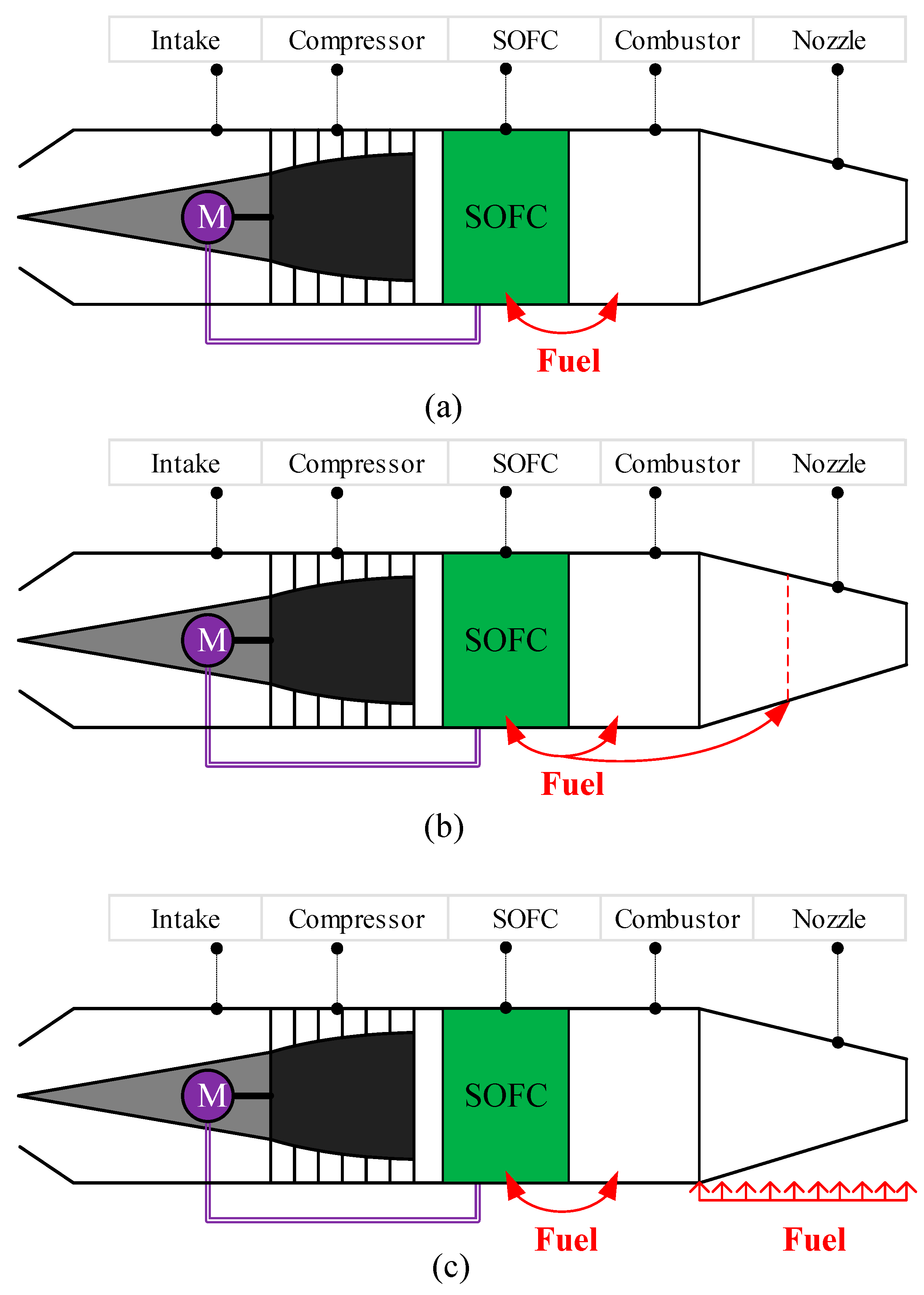
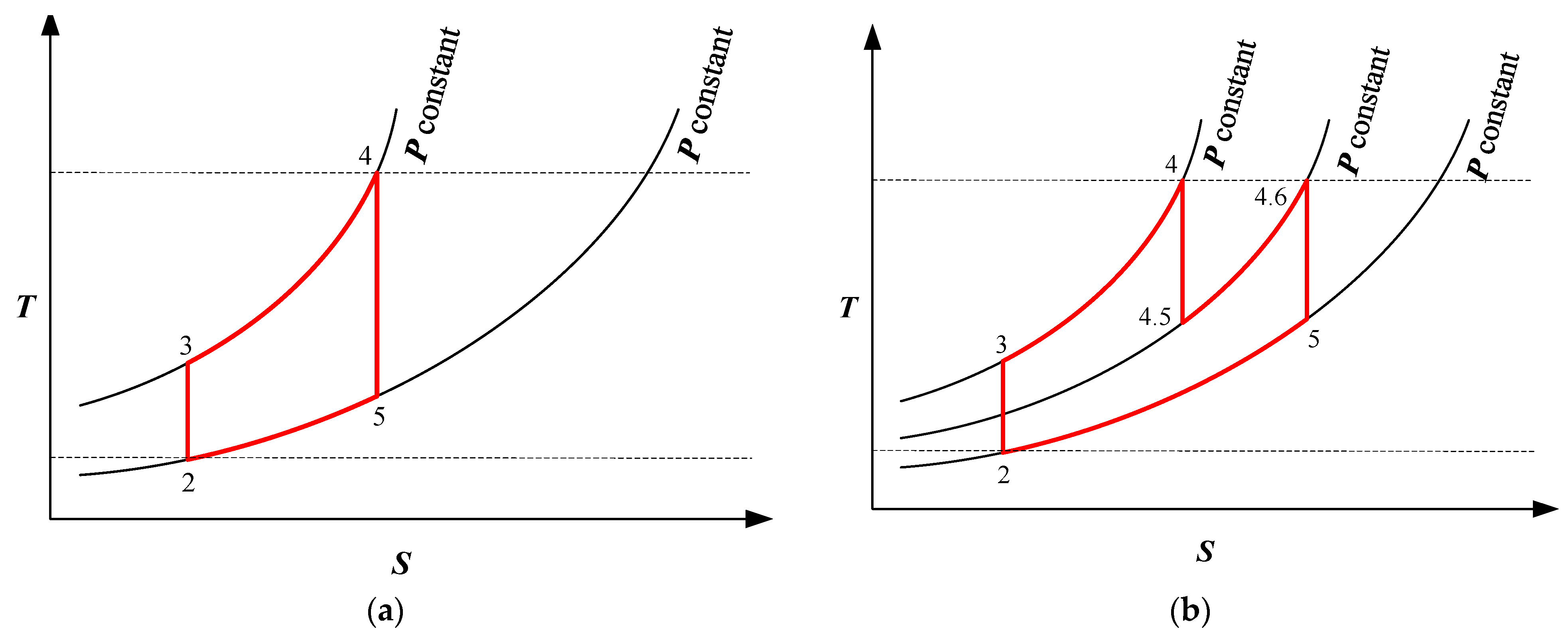
2. SOFC Brayton Cycles

Three SOFC cycles are proposed and studied in this paper, namely the ideal isobaric heating Brayton cycle with the SOFC (BFC), the ideal reheated isobaric heating Brayton cycle with the SOFC (RBFC), and the ideal isothermal expansion Brayton cycle with the SOFC (IBFC). For the basic BFC, fuel is used sequentially by the fuel cells and the nozzle. For the RBFC, the combustor exhaust is reheated in the middle of the nozzle. For the IBFC, the combustor exhaust expands in the nozzle when heat is added, which is similar to inter-turbine burners [28]. The performance of these new cycles is compared to that of an ideal Brayton cycle (BC) and an ideal reheated Brayton cycle (RBC). The schematic and T-s diagrams of the cycles are shown in Figure 1 and Figure 2. Moreover, the difference between the study and our previous paper is shown in Table 1.
The operation of Brayton cycles is ideal and that of the SOFC is not ideal in this paper. The reason is that the SOFC active area will be too huge if the current density of the SOFC is too small. It is meaningless. However, the efficiency of the components of gas turbines has been extremely high, such as burners. So, the operation of the gas turbines operated under ideal conditions is meaningful.
The schematic and T-s diagrams of ideal Brayton cycles with the SOFC are shown in Figure 1a and Figure 2c, respectively. A detailed demonstration of an ideal Brayton cycle with an SOFC can be found in the Supplementary materials. This article focuses on the analysis related to thermal cycles, while some details are reasonably simplified. The preheating process of air for SOFCs is shown in Figure 2c from state 3 to state a. The temperature of state a is in the range of 600~1000 °C. The power produced by the SOFCs is equal to the power consumed by the compressor. The working fluids are heated by the electrochemical reaction entropy production of the fuel cell, which is depicted in Figure 2c as a–b. After that, the working fluids are heated to reach the combustion temperature, T4, by the combustion reaction. The schematic diagram and T-s diagram of ideal reheated Brayton cycles with SOFCs are shown in Figure 1b and Figure 2d, which is the combination of ideal reheated Brayton cycles and SOFCs. The reheat pressure of the cycle can be higher than that of the reheated Brayton cycles. The schematic diagram and T-s diagram of an ideal isothermal expansion Brayton cycle with SOFCs are, respectively, shown in Figure 1c and Figure 2e. After isobaric heating, the working fluids undergo isothermal heating. Meanwhile, the heat added from state 4 to state 4.5 is completely converted into expansion power. Generally, the temperature of the working fluids decreases in the nozzle, which leads to the velocity increase of the working fluids. If heat is added to the working fluids by heat exchangers, the temperature of the working fluids may keep constant in the nozzle. The working fluids undergo full expansion from state 4.5 to state 5.

3. Methodology

3.1. Model Assumptions

In order to express the parameters, such as the thermal efficiency and specific thrust in equation form, some ideal assumptions have been made to derive the performance parameter equations for the three proposed novel thermodynamic cycles. The effects of the design parameters on the engine performance can be clearly shown through the equations. In addition, some configurations of actual SOFC systems are also reasonably simplified to drive the equations [28].
(1)
The working fluids are air, which is considered to be the ideal gas;
(2)
The fuel is assumed as hydrogen, and the reforming process is neglected. It can be directly used by the SOFC without being reformed;
(3)
The total pressure recovery coefficient of the fuel cells is 1;
(4)
The combustion efficiency is 1;
(5)
The expansion and compression components are assumed as isentropic;
(6)
The mass flow rate of the working fluids is assumed to be constant;
(7)
The mass flow rate of the fuel is negligible;
(8)
The energy of preheating and compressing the fuel is neglected.

3.2. Fuel Cells

According to the reference. [29], if the temperature of the reactants entering the fuel cell is not at the surrounding temperature, the maximum work and efficiency are different from those reported. Here, we assumed that the temperature of the reactants entering the SOFC is the same as that of the surrounding temperature. Moreover, the surrounding temperature is assumed as the reacting temperature. Thus, the ideal efficiency of the electrochemical reaction can be expressed as the ratio of the Gibbs free energy change and enthalpy change:
η 0 = Δ G Δ H
The current is the production of the mole rate of electrons and the Faraday constant:
I = 2 F · n
The ideal voltage is the ratio of the Gibbs free energy change and the current:
U 0 = Δ G I
The actual efficiency of the electrochemical reaction is the production of the ideal efficiency and the ratio of the actual voltage and the ideal voltage:
η fc = Δ G Δ H × U out U 0
The actual electrochemical reaction efficiency, η fc , is the function of the temperature and pressure, reaction concentration, and electrode properties. In this work, the actual efficiency is assumed as 0.7. The complex actual process calculation is ignored.
The actual power of the fuel cells is the production of the current and the actual voltage.
P fc = I × U out
If the heat addition in the cycle is Q abs , then the electric power produced by the fuel cell will be defined in Equation (6). ϕ is the fuel utilization of a fuel cell in a thermal cycle.
P fc = Q abs ϕ · η fc · Δ H ( 1 ϕ ) · Δ H + ϕ · Δ H · ( 1 η fc )
In brief,
P fc = Q abs · ( 1 ϕ · η fc 1 ) 1
The heat addition by the fuel cells can be expressed as:
Q fc = Q abs · ϕ · Δ H · ( 1 η fc ) ( 1 ϕ ) · Δ H + ϕ · Δ H · ( 1 η fc )
In brief,
Q fc = Q abs · ( 1 η fc ) ( 1 ϕ 1 ) + ( 1 η fc )
The ratio of the fuel cell power and fuel cell heat can be expressed as:
R fc = [ ( 1 ϕ 1 ) + ( 1 η fc ) ] ( 1 η fc ) · ( 1 ϕ · η fc 1 )
Particularly, the electric power produced by the fuel cells is equal to the compression power in the cycles based on the SOFC.
P fc = Q abs · ( 1 ϕ · η fc 1 ) 1 = c p · ( T out , comp T in , comp )
In addition, to examine the energy utilization ratio by the fuel cells and combustion reaction, the energy fraction is defined as Equation (12). Δ H is the heat added for the working fluids in the cycles.
ψ = P fc P fc + Δ H
The performance parameters of the ideal Brayton cycles and ideal reheated Brayton cycles are shown in the Supplementary Materials, Equations (E-S1)–(E-S14).

3.3. Ideal Brayton Cycles with the SOFC

For an ideal Carnot cycle, the output is equal to the difference between the heat absorption and heat release, which means that the heat (which did not transfer to the outside) converts into outputting power. Thus, the output “work” appears in the denominator and the “heat” appears in the numerator, correspondingly. We assumed that the constant-pressure specific heat, cp, of air is 1005 J/(K·kg), and the specific heat ratio “γ” of air is 1.4. For an ideal Brayton cycle with the SOFC (BFC), according to Figure 2c, the thermal efficiency and specific power have been derived [27] and can be expressed as:
η BFC = 1 π 1 γ γ [ 1 η fc · ϕ ]
Specific power may be expressed as:
P BFC = c p T 2 [ ( τ π γ 1 γ ) · ( 1 + η fc · ϕ 1 η fc · ϕ ) τ · π 1 γ γ + 1 ]
The nozzle exit velocity may be expressed as:
c out = 2 · c p T 2 [ ( τ π γ 1 γ ) · ( 1 + η fc · ϕ 1 η fc · ϕ ) τ · π 1 γ γ + 1 ]
The specific thrust can be expressed as:
F s = c out = 2 · c p T 2 [ ( τ π γ 1 γ ) · ( 1 + η fc · ϕ 1 η fc · ϕ ) τ · π 1 γ γ + 1 ]
The energy fraction for the RBC is defined as the ratio of the compression power and the energy addition.
ψ BFC = P comp Δ H 3 4 + P ele = ( π γ 1 γ 1 ) τ 1
According to Equation (11),
c p · T 2 · ( π γ 1 γ 1 ) = c p · ( T 4 T 3 ) · ( 1 ϕ · η fc 1 ) 1
The fuel utilization of the fuel cell in the BFC can be derived by Equation (18).
ϕ BFC = { η fc [ ( τ π γ 1 γ π γ 1 γ 1 ) + 1 ] } 1
The preheated working fluids from state 3 to the state for the high-temperature SOFC can not be recycled, because the working fluids in the nozzle enter the atmosphere after outputting the expansion power. Therefore, the energy to preheat the working fluids must be provided by the fuel energy rather than the nozzle exhaust. There is a maximum fuel utilization of the fuel cell in the BFC, which can be expressed as:
ϕ BFC , max = 1 c p · ( 600 + 273.15 T 2 ) c p · ( T 4 T 3 ) + c p · ( T 3 T 2 )
In brief,
ϕ BFC , max = τ 873.15 T 2 τ 1
In this work, T 2 = 280   K . The maximum fuel utilization of the fuel cell in the BFC is:
ϕ BFC , max = τ 3.12 τ 1
One of the limitations of the SOFC is the maximum fuel utilization. Another limitation is the temperature difference between the inlet and the outlet, which can be expressed as Equation (10):
Δ T fc = P fc { ( 1 η fc ) [ ( 1 ϕ 1 ) + ( 1 η fc ) ] · ( 1 ϕ · η fc 1 ) } · c p = T 2 · ( π γ 1 γ 1 ) { ( 1 η fc ) [ ( 1 ϕ 1 ) + ( 1 η fc ) ] · ( 1 ϕ · η fc 1 ) }
The maximum temperature difference of the fuel cells is assumed as 200 K. Therefore, the maximum pressure ratio can be expressed as:
π max = log ( γ 1 γ ) Δ T fc , max T 2 · { ( 1 η fc ) [ ( 1 ϕ 1 ) + ( 1 η fc ) ] · ( 1 ϕ · η fc 1 ) } + 1
If the highest temperature is 2000 K, the maximum compressor pressure ratio will be 32.4 with a fuel utilization of ϕ fc = 0.40. Moreover, the performance parameters of the RBFC and IBFC can be required by the same way, which is shown in Supplementary Material S2.

4. Results and Discussion
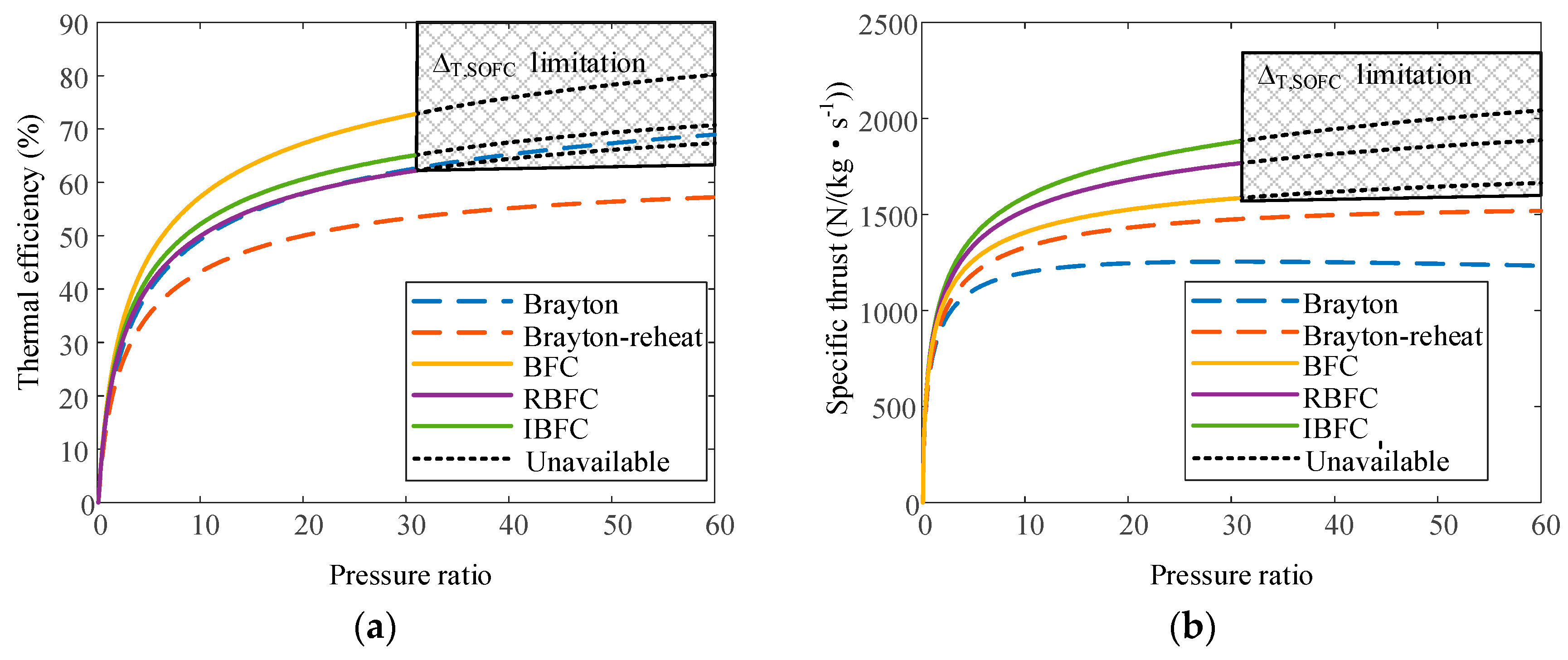
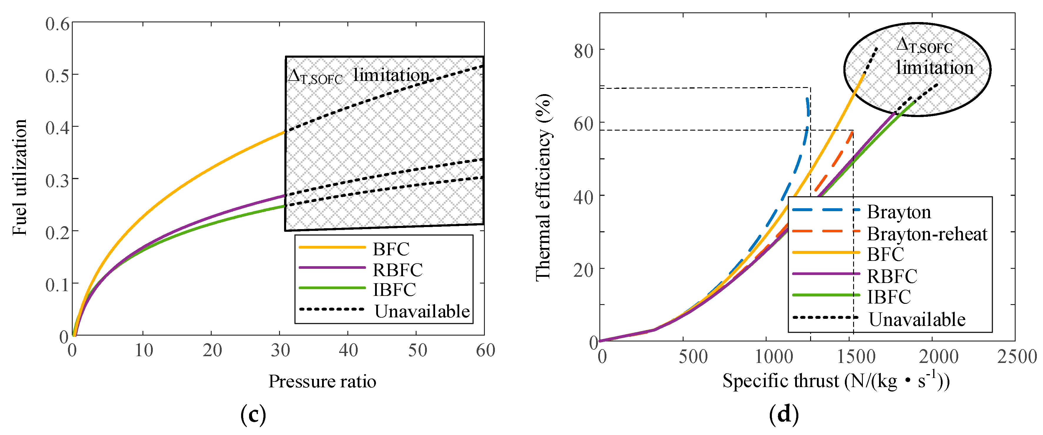
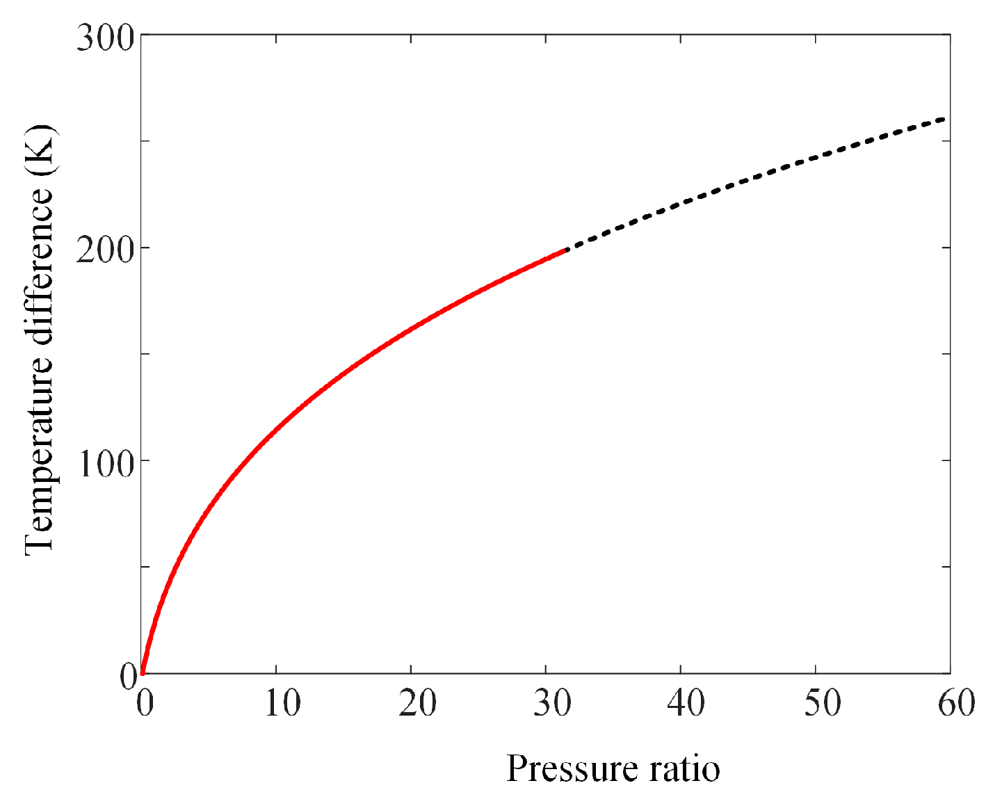
It is useful to evaluate the thermal efficiency and the specific thrust of the five cycles to measure and assess their performance. The performance parameters are mainly affected by the pressure ratio, combustion temperature, and reheat pressure ratio, which is studied in Section 4.1, Section 4.2, Section 4.3. In addition, fuel utilization can be obtained by the mathematical models in Section 3. The weight requirement and space constraint are important parameters in the aviation field, which have been researched in our previous papers [30]. The compressor power requirement and size of the SOFC were also researched. This paper mainly analyzed the performance of the new power cycle from the prospect of the first law of thermodynamics and revealed the performance potential for the cycles.

4.1. Pressure Ratio

This overall pressure ratio determines the thermal efficiency of an ideal BC, which means that the efficiency is not affected by the combustion temperature. However, the thermal efficiency of the RBC, RBC, RBFC, and IBCs require the fuel utilization of the fuel cell, fuel cell efficiency, and temperature ratios, τ 1 and τ 2 . The combustion temperature is limited up to T4 = 2000 K, and the engine consumes ambient air at T2 = 280 K, giving T4/T2 = 7.14. In addition to P4/P2 and T4/T2, the RBF and RBFCs require a fuel cell efficiency, η fc , of 0.7, and a pressure ratio across the high-pressure turbine, P4/P4.5, of 0.3. The performance of these cycles is plotted in Figure 3 for a range of pressure ratios.
The variation trends of the thermal efficiency and the specific thrust with a pressure ratio variation of the five cycles are similar, which indicates that the BFC, RBFC, and IBFC all have characteristics of the Brayton cycle to a certain extent. However, the pressure ratio of these cycles is limited by the maximum temperature difference of the fuel cells, as shown in Figure 4. The power and heat of the fuel cell increase with an increase in the pressure ratio, which leads to the increase of the SOFC temperature difference. The highest-pressure ratio will be 32.4, because the designed maximum SOFC temperature difference, Δ T fc , max of 200 K, will be reached. The conclusions are consistent with that in reference. [31], which revealed that the simplified analysis method is useful to demonstrate the effect of the fundamental parameters on the system.
The thermal efficiency of the BFC is the highest among the studied cycles because highly efficient SOFCs play a significant role in the cycle. The more fuel that is utilized by the fuel cell, the higher the efficiency. The fuel utilization of the cycle is the highest, according to the mathematical models. The thermal efficiency of the IBFC is the second highest, mainly because of isobaric heating, even though the fuel utilization of the fuel cells in the IBFC is slightly lower than the one in the BFC, as shown in Figure 3c. In addition, it is more efficient to improve the thermal efficiency by isothermal heating instead of isobaric heating. If the difference in fuel utilization between the two cycles is big, the thermal efficiency of the RBFC will be higher than that of the IBFC. The thermal efficiency of the RBFC is low due to the low fuel utilization and isobaric heating. The thermal efficiency of the BC is close to that of the RBFC. The thermal efficiency of the RBC is the lowest. The thermal efficiencies of the BFC, RBFC, and IBFCs are 73.2%, 62.5%, and 65.5%, respectively, at a pressure ratio of 32.4. The thermal efficiencies of the BC and RBCs are 63.0% and 53.7% at a pressure ratio of 60. The BFC has a distinct advantage over the BC and RBCs in terms of thermal efficiency. The theory analysis results of the hybrid cycle are consistent with the results calculated by the detailed mathematical model [31]. The thermal efficiency of the BC is far higher than that of the Brayton cycle, even though the pressure ratio of the compressor is small.
The specific thrust of the BFC is higher than that of the BC because more heat is added. The specific thrust of any of the BFC, RBFC, and IBFCs is higher than that of the RFC cycle because the compressor is powered by fuel cells, as shown in Figure 3b. The specific thrust of the IBFC is higher than that of the RBFC. It is more efficient to improve specific power by the combination of isothermal and isentropic expansion instead of the combination of isobaric heating and isentropic expansion. The specific thrust measures, the workability of air with 1 kg/s, and the thermal efficiency measures the efficiency of the fuel utilized. Therefore, the thermal efficiency of the BFC is the highest, but the specific thrust is smaller than that of the IBFC and RBFC.
The highest specific thrust of the BFC, RBFC, and IBFCs is 1591 N/(kg∙s−1), 1774 N/(kg∙s−1), and 1890 N/(kg∙s−1), respectively, at a pressure ratio of 32.4. The highest specific thrust of the BC and RBCs is 1233 N/(kg∙s−1) and 1519 N/(kg∙s−1) at a pressure ratio of 60. Any one of the BFC, RBFC, and IBFCs has an advantage over the BC and the RBC in terms of specific thrust. Figure 3d shows that the BFC has advantages in thermal efficiency and specific thrust compared to the BC and the RBC. Both the RBFC and the IBFC have advantages in specific thrust compared to other cycles.

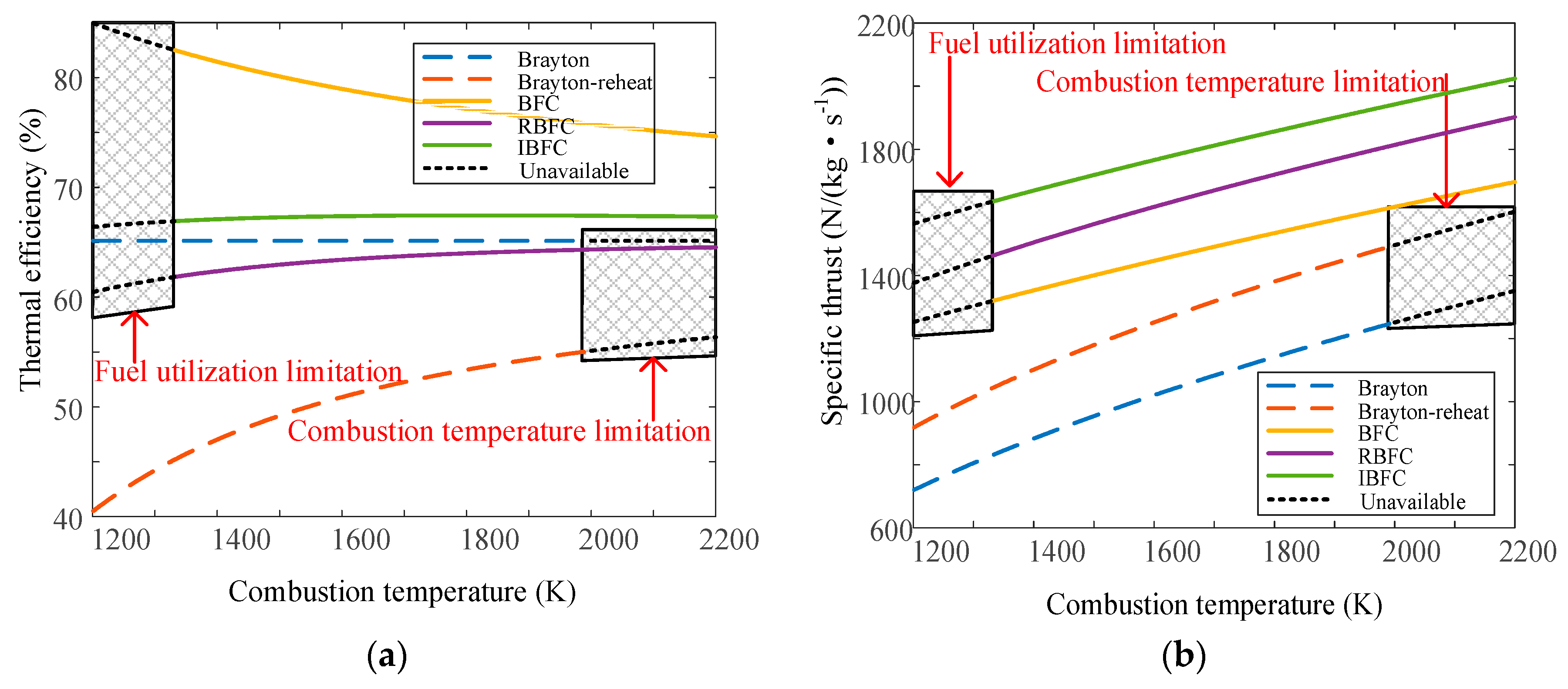
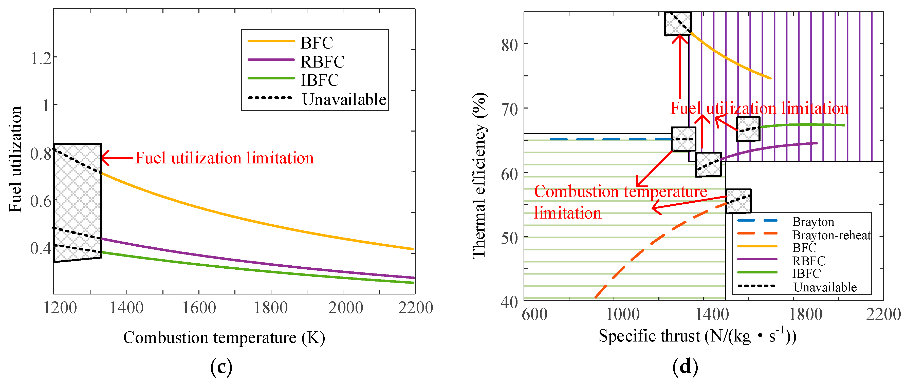
4.2. Combustion Temperature

The combustion temperature is an important parameter for improving the performance of the conventional Brayton cycle. In the present study, the performance of the five cycles was compared with the overall pressure ratio of 40 over the combustion temperature ranges. The highest combustion temperature of the BC and the RBC is 2000 K. The exhaust gas is expanded in the nozzle rather than in the turbines for the BFC, RBFC, and IBFCs. Therefore, the highest combustion temperature of these cycles is 2200 K. The performance of these cycles over a range of pressure ratios is plotted in Figure 5.
The thermal efficiency of the ideal BC is constant over a range of combustion temperatures, according to Equation (13). The thermal efficiency trend for the BC with a combustion temperature variation is contrary to the one for the BFC in Figure 5a. As the combustion temperature increases, the fuel utilization of the BFC decreases, as shown in Figure 5c, which leads to a decrease in thermal efficiency. The reason is explained in Section 4.1. The thermal efficiency trends with a combustion temperature variation of the RBC, the RBFC, and the IBFC are similar in Figure 5a. The reason is that the fuel utilization of these cycles is lower than that of the BFC. The effect of the thermal efficiency improvement by the increased combustion temperature is offset by the decreased fuel utilization of the fuel cells. The thermal efficiency of the RBFC and the IBFC is close to constant. The thermal efficiency of the RBFC ranges from 62.0% to 64.5% at combustion temperatures of 1200 to 2000 K. The IBFC ranges from 67.0% to 67.3%. For the BC and the RBC, there is a limitation of the maximum combustion temperature, as shown in Figure 5c, which is 2000 K. The BFC, RBFC, and IBFCs can operate at a further high combustion temperature of 2200 K in this work. The limitation of these cycles is the maximum fuel utilization of 0.7. The energy of the compression and first heat addition is just taken into account when calculating the limitation value of the fuel cell’s fuel utilization. Therefore, the overall fuel utilization of the RBFC and the IBFC is below 0.7, as shown in Figure 5c. The minimum combustion temperature is 1350 K at a maximum fuel utilization of 0.7. The maximum thermal efficiency of the BFC at the lowest combustion temperature is 82.2%, which is higher than that of the BC at 65.1% and the RBC at 55.1% at the highest combustion temperature.
The specific thrust of these cycles increases significantly with the increase of the combustion temperature due to the increase in the expansion temperature ratio. The specific thrust of the BFC, RBFC, and IBFCs at a combustion temperature of 2200 K is 1696 N/(kg∙s−1), 1902 N/(kg∙s−1), and 2014 N/(kg∙s−1), respectively, which is extraordinarily higher than that of the BC of 1251 N/(kg∙s−1) and the RBC of 1496 N/(kg∙s−1) at the combustion temperature of 2000 K. Figure 5d shows that the curves of the BFC, RBFC, and IBFCs are at the top right corner of the specific thrust–thermal efficiency diagram compared with the BC and the RBC when the combustion temperature varies. It revealed that increasing the combustion temperature is more beneficial for the BFC, RBFC, and IBFC.

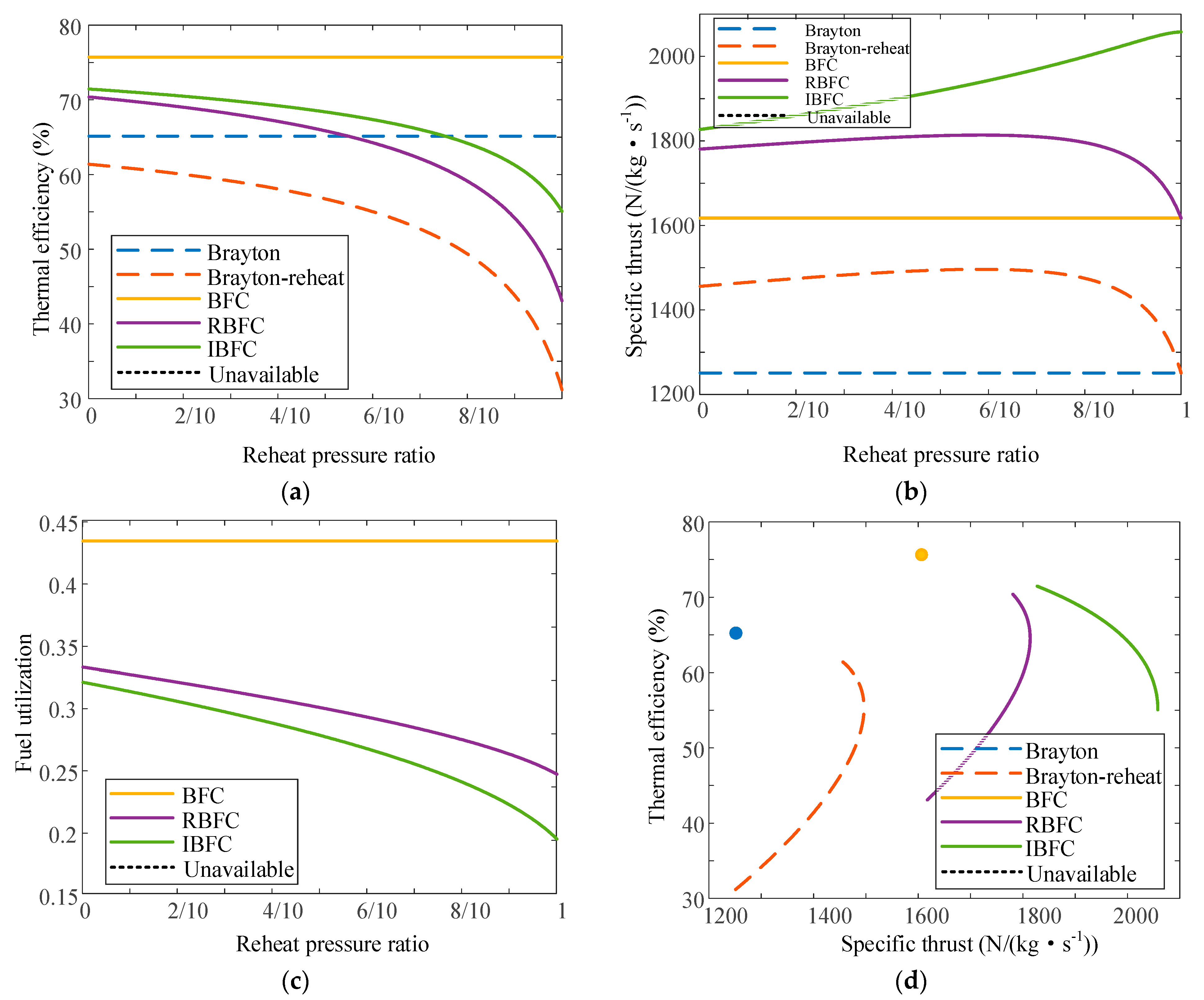
4.3. Reheat Pressure Ratio

For the RBC, RBFC, and IBFC, the pressure of the reheat position is an important parameter and influences the specific thrust improvement of these cycles. The reheating process occurs in the afterburner for these cycles. The reheat pressure depends on the afterburner position in the nozzle. The reheat pressure ratio is defined as a value between the afterburner pressure and atmospheric pressure. When the reheat pressure ratio is 0, the reheat pressure is the afterburner pressure. When the reheat pressure ratio is 1, the reheat heat pressure is the atmospheric pressure. In this work, the performance of the five cycles is compared under the conditions of the overall pressure ratio of 40 and the combustion temperature of 2000 K for a range of reheat pressure. The performance of these cycles is plotted in Figure 6.
The thermal efficiency and the specific thrust of the BC and BFCs are constant due to the absence of the reheating process over a range of reheat pressure ratios. The thermal efficiency of the BFC, RBFC, and IBFCs decreases with the increase of the reheat pressure ratio because of huge entropy loss in the reheating process [32]. As the reheat pressure ratio increases, the specific thrust increases slowly and then decreases sharply in the RBFC and RBCs. The reason is that more heat can be added as the reheat pressure ratio increases. When the reheat pressure is moderately high, the nozzles can output more power. When the reheat pressure is extremely low, the pressure ratio of the afterburner and the atmosphere is extremely low, which causes little power to be produced by the nozzles. Therefore, the conclusions and reasons here are consistent with those (the specific thrust of the BFC is higher than that of the BC) in Section 4.1, but the effect is not obvious if the reheat pressure is too small. In contrast to that of the RBFC, the specific thrust of the IBFC increases continuously with the increase of the reheat pressure ratio. The maximum specific thrust of the IBFC is 2058 N/(kg∙s−1). In the process of isothermal expansion, the added heat is completely converted into expansion power. The higher the pressure ratio is, the more heat is added. Therefore, the expansion power increases. Figure 6d shows that the IBFC has an advantage over the RBFC in achieving high specific thrust and high thermal efficiency.

5. Conclusions

The effects of the pressure ratio, combustion temperature, and other thermodynamic parameters on new hybrid cycles have been demonstrated based on the derivation of the performance parameter. Thermodynamic analysis has shown the advantages of the Brayton cycle integrated with an SOFC for aircraft propulsion systems, compared with the Brayton cycles in this paper. The main conclusions are as follows:
(1)
The thermal efficiency and specific thrust of the ideal BFC both increase with the increase of the pressure ratio. However, there is a maximum pressure ratio of 32.4 due to the limitation of the temperature difference between the fuel cell inlet and the outlet. The highest thermal efficiency of the BFC is 73.2% at a pressure ratio of 32.4. The highest thermal efficiency of the BC is 63.0% at a pressure ratio of 60. The BFC has an obvious advantage over the BC and the RBC in thermal efficiency.
(2)
The thermal efficiency of the BFC decreases as the combustion temperature increases. The thermal efficiencies of the RBFC and IBFC show the opposite trends. The maximum thermal efficiency of the BFC at the lowest combustion temperature is 82.2%, while that of the BC is 65.1%.
(3)
The thermal efficiency of the RBFC and the IBFC decreases with an increase in the reheat pressure ratio. The specific thrust increases slowly and then decreases sharply in the RBFC. The specific thrust of the IBFC increases with the increase of the reheat pressure ratios. The maximum specific thrust of the IBFC is 2058 N/(kg∙s−1).
(4)
Even though the application of the innovative power cycle composed of fuel cells and gas turbines on aircraft is challenging, it provides a new prospect for the development of low-emission aircraft. The electricity aircraft will save fossil fuel and produce little carbon dioxide emission largely.

Supplementary Materials

The following supporting information can be downloaded at: https://www.mdpi.com/article/10.3390/su15032805/s1, Figure S1: the schematic diagram of an ideal Brayton cycle with SOFCs; Figure S2: detailed Scheme diagrams of the ideal Brayton cycles with solid oxide fuel cells; Figure S3: verification of the SOFC model; Figure S4: validation assessment of the SOFC model. References [33,34,35,36] are cited in Supplementary Materials S1 and S2.

Author Contributions

Methodology, T.Z.; Software, S.Z.; Investigation, K.C. and P.D.; Data curation, F.G.; Writing—original draft, Z.J.; Writing—review & editing, J.Q. All authors have read and agreed to the published version of the manuscript.

Funding

This research was funded by National Natural Science Foundation of China (51906177).

Institutional Review Board Statement

Not applicable.

Informed Consent Statement

Not applicable.

Data Availability Statement

Not applicable.

Conflicts of Interest

The authors declare no conflict of interest.

Nomenclature

AArea (m2)Subscripts
cVelocity (m/s)aAir
cpConstant-pressure specific heat
(J/(kg.K)/s)
absHeat addition
FFaraday constant (96,485 C/mol)compCompressor
FSSpecific thrust (N/(kg/s))fcFuel cell
GGibbs free energy (J/mol/s)gExhaust
HEnthalpy (J/mol/s)maxMaximum
ICurrent (A)outOpen circuit voltage
nMole rate of electronsoutOutlet
pPressure (Pa)BCBrayton cycle
PPower (J/s)BFCBrayton cycle with SOFC
QThe amount of heat (J/s)IBFCIsothermal Brayton cycle with SOFC
RfcRatio of fuel cell power and heatRBCReheating Brayton cycle
TTemperature (K)RBFCReheated Brayton cycle with SOFCs
UVoltage (V)PEMFCProton exchange membrane fuel cell
W Mass flow (kg/s)SOFCSolid oxide fuel cell
Δ T , SOFC Temperature difference between SOFC inlet and outlet
ψ Ratio of electric power and total powerSuperscript
τ Temperature ratio0Ideal conditions
ϕFuel utilization
π Pressure ratio
γ Ratio of specific heat
η Thermal efficiency

References

  1. Roth, B.; Giffin, R. Fuel cell hybrid propulsion challenges and opportunities for commercial aviation. In Proceedings of the 46th AIAA/ASME/SAE/ASEE Joint Propulsion Conference & Exhibit, Nashville, TN, USA, 25–28 July 2010; p. 6537. [Google Scholar]
  2. Rutledge, J.L.; Polanka, M.D. Efficiency of an Ideal Brayton Cycle with a Constant-Volume Interturbine Burner. J. Propuls. Power 2015, 31, 970–976. [Google Scholar] [CrossRef]
  3. Sarmah, P.; Gogoi, T.K.; Das, R. Estimation of operating parameters of a SOFC integrated combined power cycle using differential evolution based inverse method. Appl. Therm. Eng. 2017, 119, 98–107. [Google Scholar] [CrossRef]
  4. Hwang, S.-J.; Kim, S.-G.; Kim, C.-W.; Lee, Y.-G. Aerodynamic Design of the Solar-Powered High Altitude Long Endurance (HALE) Unmanned Aerial Vehicle (UAV). Int. J. Aeronaut. Space Sci. 2016, 17, 132–138. [Google Scholar] [CrossRef]
  5. Stoia, T.; Atreya, S.; O’Neil, P. A Highly Efficient Solid Oxide Fuel Cell Power System for an All-Electric Commuter Airplane Flight Demonstrator. In Proceedings of the 54th AIAA Aerospace Sciences Meeting, San Diego, CA, USA, 4–8 January 2016; p. 1024. [Google Scholar]
  6. Borer, N.K.; Geuther, S.C.; Litherland, B.L.; Kohlman, L.W. Design and Performance of a Hybrid-Electric Fuel Cell Flight Demonstration Concept. In Proceedings of the Aviation Technology, Integration, and Operations Conference, Atlanta, GA, USA, 25–29 June 2018; p. 3357. [Google Scholar]
  7. Fernandes, M.D.; Andrade, S.T.d.P.; Bistritzki, V.N.; Fonseca, R.M.; Zacarias, L.G.; Goncalves, H.N.C.; de Castro, A.F.; Domingues, R.Z.; Matencio, T. SOFC-APU systems for aircraft: A review. Int. J. Hydrogen Energy 2018, 43, 16311–16333. [Google Scholar] [CrossRef]
  8. Lapeña-Rey, N.; Mosquera, J.; Bataller, E.; Ortí, F. First fuel-cell manned aircraft. J. Aircr. 2010, 47, 1825–1835. [Google Scholar] [CrossRef]
  9. Correa, G.; Santarelli, M.; Borello, F.; Cestino, E.; Romeo, G. Flight test validation of the dynamic model of a fuel cell system for ultra-light aircraft. Proc. Inst. Mech. Eng. Part G J. Aerosp. Eng. 2015, 229, 917–932. [Google Scholar] [CrossRef]
  10. Bégot, S.; Harel, F.; Candusso, D.; François, X.; Péra, M.-C.; Yde-Andersen, S. Fuel cell climatic tests designed for new configured aircraft application. Energy Convers. Manag. 2010, 51, 1522–1535. [Google Scholar] [CrossRef]
  11. Renau, J.; Barroso, J.; Lozano, A.; Nueno, A.; Sánchez, F.; Martín, J.; Barreras, F. Design and manufacture of a high-temperature PEMFC and its cooling system to power a lightweight UAV for a high altitude mission. Int. J. Hydrogen Energy 2016, 41, 19702–19712. [Google Scholar] [CrossRef]
  12. Lapeña-Rey, N.; Blanco, J.; Ferreyra, E.; Lemus, J.; Pereira, S.; Serrot, E. A fuel cell powered unmanned aerial vehicle for low altitude surveillance missions. Int. J. Hydrogen Energy 2017, 42, 6926–6940. [Google Scholar] [CrossRef]
  13. Kim, T. NaBH4 (sodium borohydride) hydrogen generator with a volume-exchange fuel tank for small unmanned aerial vehicles powered by a PEM (proton exchange membrane) fuel cell. Energy 2014, 69, 721–727. [Google Scholar] [CrossRef]
  14. Baldic, J.; Osenar, P.; Lauder, N.; Launie, P. Fuel cell systems for long duration electric UAVs and UGVs. In Proceedings of the Defense Transformation and Net-Centric Systems 2010, Orlando, FL, USA, 6–8 April 2010; Volume 7707, p. 770703. [Google Scholar]
  15. González-Espasandín, Ó.; Leo, T.J.; Raso, M.A.; Navarro, E. Direct methanol fuel cell (DMFC) and H2 proton exchange membrane fuel (PEMFC/H2) cell performance under atmospheric flight conditions of Unmanned Aerial Vehicles. Renew. Energy 2019, 130, 762–773. [Google Scholar] [CrossRef]
  16. Marchant, W.; Tosunoglu, S. Rethinking Wildfire Suppression With Swarm Robotics. In Proceedings of the 29th Florida Conference on Recent Advances in Robotics. 2016. Available online: https://www.semanticscholar.org/paper/Rethinking-Wildfire-Suppression-With-Swarm-Robotics-Marchant-Tosunoglu/8c4d7e9a524592c1f0d83fcd9868241454d72290 (accessed on 8 November 2022).
  17. Giacoppo, G.; Barbera, O.; Briguglio, N.; Cipitì, F.; Ferraro, M.; Brunaccini, G.; Erdle, E.; Antonucci, V. Thermal study of a SOFC system integration in a fuselage of a hybrid electric mini UAV. Int. J. Hydrogen Energy 2017, 42, 28022–28033. [Google Scholar] [CrossRef]
  18. Chu, D.; Jiang, R.; Dunbar, Z.; Grew, K.; McClure, J. Fuel cell powered small unmanned aerial systems (UASs) for extended endurance flights. In Proceedings of the Unmanned Systems Technology XVII, Baltimore, MD, USA, 21–23 April 2015; Volume 9468, p. 94680E. [Google Scholar]
  19. Ding, X.; Lv, X.; Weng, Y. Coupling effect of operating parameters on performance of a biogas-fueled solid oxide fuel cell/gas turbine hybrid system. Appl. Energy 2019, 254, 113675. [Google Scholar] [CrossRef]
  20. Choi, W.; Kim, J.; Kim, Y.; Kim, S.; Oh, S.; Song, H.H. Experimental study of homogeneous charge compression ignition engine operation fuelled by emulated solid oxide fuel cell anode off-gas. Appl. Energy 2018, 229, 42–62. [Google Scholar] [CrossRef]
  21. Hosseinpour, J.; Sadeghi, M.; Chitsaz, A.; Ranjbar, F.; Rosen, M.A. Exergy assessment and optimization of a cogeneration system based on a solid oxide fuel cell integrated with a Stirling engine. Energy Convers. Manag. 2017, 143, 448–458. [Google Scholar] [CrossRef]
  22. Himansu, A.; Freeh, J.E.; Steffen Jr, C.J.; Tornabene, R.T.; Wang, X.-Y.J. Hybrid solid oxide fuel cell/gas turbine system design for high altitude long endurance aerospace missions. In Proceedings of the International Conference on Fuel Cell Science, Engineering and Technology, Irvine, CA, USA, 19–21 June 2006; Volume 42479, pp. 573–583. [Google Scholar]
  23. Aguiar, P.; Brett, D.; Brandon, N. Solid oxide fuel cell/gas turbine hybrid system analysis for high-altitude long-endurance unmanned aerial vehicles. Int. J. Hydrogen Energy 2008, 33, 7214–7223. [Google Scholar] [CrossRef]
  24. Waters, D.F.; Cadou, C.P. Engine-integrated solid oxide fuel cells for efficient electrical power generation on aircraft. J. Power Sources 2015, 284, 588–605. [Google Scholar] [CrossRef]
  25. Yanovskiy, L.S.; Baykov, A.; Raznoschikov, V.; Averkov, I. Alternative Fuels and Perspectives Solid Oxide Fuel Cells Usage in Air Transport. ECS Trans. 2013, 57, 149–160. [Google Scholar] [CrossRef]
  26. Okai, K.; Nomura, H.; Tagashira, T.; Nishizawa, A. Effects of Fuel Type on Aircraft Electric Propulsion with SOFC/GT Hybrid Core. In Proceedings of the AIAA/SAE/ASEE Joint Propulsion Conference, Atlanta, GA, USA, 10–12 July 2017. [Google Scholar]
  27. Ji, Z.; Qin, J.; Cheng, K.; Liu, H.; Zhang, S.; Dong, P. Thermodynamic analysis of a solid oxide fuel cell jet hybrid engine for long-endurance unmanned air vehicles. Energy Convers. Manag. 2019, 183, 50–64. [Google Scholar] [CrossRef]
  28. Sirignano, W.A.; Dunn-Rankin, D.; Liu, F.; Colcord, B.; Puranam, S.J.A.J. Turbine Burners: Performance Improvement and Challenge of Flameholding. AIAA J. 2015, 50, 1645–1669. [Google Scholar] [CrossRef] [Green Version]
  29. Haseli, Y. Maximum conversion efficiency of hydrogen fuel cells. Int. J. Hydrogen Energy 2018, 43, 9015–9021. [Google Scholar] [CrossRef]
  30. Ji, Z.; Rokni, M.M.; Qin, J.; Zhang, S.; Dong, P. Performance and size optimization of the turbine-less engine integrated solid oxide fuel cells on unmanned aerial vehicles with long endurance. Appl. Energy 2021, 299, 117301. [Google Scholar] [CrossRef]
  31. Ji, Z.; Qin, J.; Cheng, K.; Dang, C.; Zhang, S.; Dong, P. Thermodynamic performance evaluation of a turbine-less jet engine integrated with solid oxide fuel cells for unmanned aerial vehicles. Appl. Therm. Eng. 2019, 160, 114093. [Google Scholar] [CrossRef]
  32. Liu, F.; Sirignano, W.A. Turbojet and turbofan engine performance increases through turbine burners. J. Propuls. Power 2001, 17, 695–705. [Google Scholar] [CrossRef]
  33. Thacker, B.H.; Doebling, S.W.; Hemez, F.M.; Anderson, M.C.; Pepin, J.E.; Rodriguez, E.A. Concepts of model verification and validation. Los Alamos Natl. Lab 2002. [Google Scholar] [CrossRef]
  34. Aguiar, P.; Adjiman, C.S.; Brandon, N.P. Anode-supported intermediate temperature direct internal reforming solid oxide fuel cell. I: Model-based steady-state performance. J. Power Sources 2004, 138, 120–136. [Google Scholar] [CrossRef]
  35. American Institute of Aeronautics and Astronautics. AIAA Guide for the Verification and Validation of Computational Fluid Dynamics Simulations; American Institute of Aeronautics and Astronautics: Reston, VA, USA, 1998. [Google Scholar]
  36. Suwanwarangkul, R.; Croiset, E.; Entchev, E.; Charojrochkul, S.; Pritzker, M.D.; Fowler, M.W.; Mahaudom, H. Experimental and modeling study of solid oxide fuel cell operating with syngas fuel. J. Power Sources 2006, 161, 308–322. [Google Scholar] [CrossRef]
Figure 1. The schematic diagrams of engines based on different cycles; the (a) BFC, (b) RBFC, and (c) IBFC.
Sustainability 15 02805 g001
Figure 2. The T-s diagrams of the different cycles; the (a) Brayton cycle, (b) reheated Brayton cycle, (c) BFC, (d) RBFC, and (e) IBFC.
Sustainability 15 02805 g002aSustainability 15 02805 g002b
Figure 3. The performance of the cycles; (a) thermal efficiency, (b) specific thrust, (c) fuel utilization, and (d) overall performance vs the pressure ratio with a combustion temperature of 2000 K and a reheat pressure ratio of 0.3.
Sustainability 15 02805 g003aSustainability 15 02805 g003b
Figure 4. Temperature difference of SOFCs vs the compressor ratio.
Sustainability 15 02805 g004
Figure 5. The performance of the cycles; (a) thermal efficiency, (b) specific thrust, (c) fuel utilization, and (d) overall performance vs the combustion temperature with the overall pressure ratio of 40 and reheat pressure ratio of 0.3.
Sustainability 15 02805 g005aSustainability 15 02805 g005b
Figure 6. The performance of the cycles; (a) thermal efficiency, (b) specific thrust, (c) fuel utilization, and (d) overall performance vs the reheat pressure ratios with the overall pressure ratio of 40 and combustion temperature of 2000 K.
Sustainability 15 02805 g006
Table 1. Comparisons of the study and the previous study.
ItemsThe StudyPrevious Study
CycleIdealPractical
Research methodEquation derivationDetailed thermodynamic model
Research contentFundamental thermodynamic parametersComplex system performance
Disclaimer/Publisher’s Note: The statements, opinions and data contained in all publications are solely those of the individual author(s) and contributor(s) and not of MDPI and/or the editor(s). MDPI and/or the editor(s) disclaim responsibility for any injury to people or property resulting from any ideas, methods, instructions or products referred to in the content.

