Article

Laboratory Experimental Study on the Pressure Relief Effect of Boreholes in Sandstone under High-Stress Conditions

1
School of Safety Engineering, China University of Mining and Technology, Xuzhou 221116, China
2
School of Energy Scinence and Engineering, Henan Polytechnic University, Jiaozuo 454003, China
3
School of Resources and Civil Engineering, Northeastern University, Shenyang 110819, China
*
Author to whom correspondence should be addressed.
Sustainability 2023, 15(21), 15557; https://doi.org/10.3390/su152115557
Submission received: 31 July 2023 / Revised: 5 October 2023 / Accepted: 27 October 2023 / Published: 2 November 2023
(This article belongs to the Special Issue Advancing Sustainability in Geotechnical Engineering)

Abstract

:
To study the effects of deep rock drilling pressure relief under high stress conditions in enhanced geothermal systems, two kinds of drilling pressure relief experiments were conducted on sandstone—the staged drilling of pressure relief holes before peak stress and one-time drilling. Pressure relief experiments were carried out on sandstone with two borehole methods of the stage-by-stage drilling and one-time drilling of pressure relief boreholes ahead of the experiments. FLAC3D was used to analyze the plastic zone evolution during drilling and the relationship between stress and plastic zone volume. The results reveal the pre-peak stress change characteristics and pressure relief features of non-prefabricated boreholes under high stress. The experiments show that the staged drilling of pressurized samples involves stages of rapid and gradual decreases in stress, with total relief amplitudes increasing but single-borehole relief decreasing with more holes. Under the same conditions, staged drilling has better relief effects and results in greater energy dissipation, indicating that incremental pre-peak pressure relief is beneficial for reducing the surrounding rock’s impact tendency and improving stability. The research results can provide good guidance and reference for the long-term stability analysis of borehole-containing rock and rock burst hazard control.

1. Introduction

Due to its cleanliness and widespread spatial distribution, geothermal resources have become a key clean energy source prioritized by countries around the world for research and development [1,2,3,4]. China has abundant geothermal resources widely distributed across the country. Sedimentary basin-type hot dry rock resources are an important type of geothermal energy, mainly distributed in northwestern, northern, and northeastern China. Hot dry rocks refer to deep high-temperature, low-permeability rock formations without naturally existing water bodies inside. Artificial geothermal reservoirs need to be formed through measures such as artificial water injection and hydraulic fracturing to achieve geothermal energy extraction and utilization. Enhanced geothermal systems are engineered geothermal systems that economically extract deep geothermal energy from low-permeability rocks by artificially creating geothermal reservoirs, which means developing geothermal energy from hot dry rocks [2,3,4,5].
Drilling pressure relief is commonly used for surrounding rock and rock burst hazards and is one of the important measures for preventing rock bursts. It has the advantages of simple operation, safe construction and a good relief effect [6,7,8,9]. Meanwhile, drilling pressure relief can also be used to develop the heat storage layer for enhanced geothermal systems, but there are also some technical difficulties and risks involved. Drilling pressure relief can generate or activate large-scale fracture networks in hot dry rocks, which can be accessed through seismic monitoring and directional drilling. This can improve the permeability and hydraulic connectivity of the heat storage layer, enabling fluid circulation and heat exchange in the fracture networks. However, drilling pressure relief may also lead to induced seismicity that poses threats to the environment and humans. Therefore, accurate parameter design and stringent safety control are needed for drilling pressure relief to achieve optimal relief effects and minimize seismic impacts.
Scholars have carried out many experiments, theoretical derivations and numerical simulations on borehole pressure relief for rock burst hazards. W. D. Ortlepp and T. R. Stacy [10] pointed out that stress relief during excavation under high-stress conditions may cause strain rock bursts. P K KAISER [11] pointed out that the pressure relief effect and free surface generated by roadway excavation change the triaxial compression equilibrium state of deep rock and provide the conditions necessary for the occurrence of rock bursts. Liu Honggang et al. [12] uncovered the mechanism of borehole pressure relief by simulating engineering examples using the RFPA and ANSYS software. Zhang Ying et al. [13] established an elastoplastic model of the coal body around boreholes using COMSOL software and found that coal strength, burial depth and borehole diameter are the main factors controlling the pressure relief range of boreholes. Zheng He et al. [14] carried out a numerical simulation of deep roadways and found that borehole pressure relief technology can effectively release the deformation and destruction energy of surrounding rock and improve the stress environment. Zhu Staou et al. [15] proposed the concept of the energy dissipation index through rock mechanics experiments and deduced the relationship between the energy dissipation index and the impact energy index to determine the anti-impact drill hole parameters. Wang Shuwen et al. [16] proposed the concept of borehole energy dissipation rate from the perspective of energy by analyzing the failure mechanism of borehole-surrounding rock. The pressure relief effect is exponentially related to borehole diameter and negatively correlated with coal strength. Wang Meng et al. [17] inverted the mechanical parameters of rock mass using FLAC3D and proposed a method for deter-mining the key parameters affecting the pressure relief effect. Jia Chuanyang et al. [18] found that borehole parameters have a great influence on the pressure relief effect based on indoor tests and PFC software simulations. The larger the borehole diameter and depth and the smaller the spacing, the better the pressure relief effect. The fundamental reason for borehole pressure relief is the stress release caused by fracture penetration. Qin Zihan et al. [19] detected the pressure relief effect zone using electromagnetic wave CT detection technology and found that coal strength, borehole diameter and spacing are the main factors affecting the pressure relief effect. Ma Binwen et al. [20] deduced a boundary equation for the borehole pressure relief zone based on the theory of impact ground pressure stress control. Zhao Zhenhua et al. [21] carried out a stress relaxation test using amphibolite samples containing pressure relief holes and determined the mechanism underlying pressure relief holes during the stress relaxation process. Lin, P. et al. [22] explored the crack evolution mechanism of granite samples with prefabricated boreholes of different sizes, spacing and layouts using a uniaxial compression test. The test results show that, under the interaction of stresses, three typical cracks are generated around the borehole: shear cracks, tensile cracks and mixed (shear–tensile) cracks. Zhao, T.B. et al. [23] further explored the failure characteristics and mechanisms of samples with different borehole arrangements via PFC and found that shear accompanied by splitting failure is the main failure mode for samples with different borehole diameters, while, for samples with different numbers of boreholes in a row, splitting accompanied by shear failure is the main failure mode. However, splitting or shear failure modes may occur for samples containing a different number of borehole rows. Huang, B. et al.’s [24] study on the acoustic emission characteristics of samples with different borehole diameters also confirmed that, when the borehole diameter is larger, the AE activity before the peak strength point is stronger, and the bearing capacity of the sample is significantly weaker.
In summary, most of the current research is limited to theoretical analysis and numerical simulation, with less systematic experimental verification. The understanding of borehole pressure relief effects and laws under high-stress conditions is still insufficient, and the study of the evolution law of the stress field during dynamic drilling is insufficient. Therefore, it is of great significance for research on borehole pressure relief in rock burst hazards to analyze the peak stress change characteristics by drilling multiple pressure relief boreholes in stressed sandstone samples.

2. Specimen Test Methods

2.1. Specimen Preparation

Sandstone was selected as the research object for the experiments. The samples were taken from the same sandstone block and processed by cutting and grinding them into cubic specimens with length 80 mm, width 80 mm and height 80 mm. The flatness of the end faces was less than 0.02 mm, meeting the standards for rock mechanics testing. The geometrical parameters are shown in Table 1.

2.2. Test Methods

The RMT-150-B electrohydraulic servo test system was used for the uniaxial compression tests. The axial load was measured using a 1000 kN force sensor with a precision of 1.0 × 10⁻³ kN. The axial compressive deformation was measured using a 5.0 mm displacement sensor, and the circumferential deformation was measured using two 2.5 mm displacement sensors. The deformation precision was 1.0 × 10⁻³ mm. Displacement loading was applied throughout the test at a loading rate of 0.002 mm/s, as shown in Figure 1.
Preload stress: Uniaxial compression tests on intact samples yielded an average peak stress of 67.73 MPa. A preload stress that is too low cannot simulate the stress environment of deep rock, while excessive stress may cause sample failure during borehole drilling under pressure, making it difficult to conduct pressurized borehole tests. The preload stress was determined to be 38.50 MPa.
Pressure relief borehole parameters: Loading was stopped upon reaching the preload stress, with the hydraulic cylinder displacement maintained. Pressure relief boreholes were then drilled into the samples. The boreholes were drilled vertically into the end faces of the samples using a fixed electric drill. Reference [17] indicates that the relief effect is most significant when the borehole spacing is 2–6 times the borehole diameter. Thus, 8 mm diameter through-holes with 80 mm depth were adopted, with 40 mm spacing between the borehole centers in the multi-borehole samples, as shown in Figure 2.
Two borehole drilling modes were implemented: staged drilling and one-off drilling. Staged drilling refers to drilling the next borehole in multi-borehole samples after the stress of the previous borehole has stabilized. One-off drilling means immediately drilling subsequent boreholes upon completing the first without waiting for stress stabilization (Figure 3).

3. Test Results and Analysis

3.1. Staged Drilling Stress Evolution Characteristics for Pressure Relief Holes

Figure 4 shows the stress–time curves for staged pressure relief borehole drilling in the samples. It took 461 s, 554 s and 581 s for the stresses in B11, B21 and B32 to reach the preload stress, respectively. Figure 4 indicates that B11 has a shorter compaction stage and faster rate of increase in stress, meaning fewer pores in the sample. In the first stage of pressure relief borehole drilling, the sample stresses dropped sharply under the action of pressure relief holes: the stresses decreased to 30.75 MPa, 30.92 MPa and 29.94 MPa in B11, B21 and B32, with reductions of 20.1%, 19.7% and 23.4%, respectively. In the second drilling stage, the stress reduction was slower than that in the first stage, and the relief amplitude decreased: the B21 stress decreased to 27.68 MPa with a total reduction of 28.1%, 10.5% less than that in the first stage; the B32 stress decreased to 26.70 MPa with a total reduction of 30.6%, 10.8% less than that in the first stage. In the third drilling stage of B32, the stress decreased to 25.15 MPa with a total reduction of 34.6%, 5.8% less than that in the second stage. The samples were reloaded after completing borehole drilling, with lower peak stresses compared to intact samples. B11 and B32 showed brittle failure, while B21 exhibited ductile failure.
Taking B32 as an example, we characterize the stress evolution of the staged unpressurized drilling. From 0 to 581 s, the slope and increase rate of the stress–time curve rose under uniaxial compression, indicating pore compaction in the sample. The stress increased to the preload stress at 581 s, and then borehole drilling started. At 642 s after drilling was completed, the stress dropped sharply to 29.49 MPa due to mechanical disturbance and stress concentration, decreasing by 23.4%. From 642 s to 1210 s, the stress remained unchanged, suggesting that the pressure relief of the first borehole had reached its limit. The second borehole was drilled at 1211 s and completed at 1282 s. The stress decreased to 26.7 MPa with a reduction of 30.6%. Unlike the cliff-like drop in the first stage, the second stage showed a more gradual stress reduction, indicating microcrack propagation in the sample. The stress stabilized until 1817 s. The third borehole was drilled at 1818 s and completed at 1921 s, reducing the stress to 25.15 MPa with an amplitude of 34.6%. The stress remained stable from the completion of drilling to 2411 s, marking the end of the third stage of pressure relief. Reloading at 2412 s increased the stress to 49.38 MPa at 2596 s, at which point brittle failure occurred with stress dropping to 0 MPa. This suggests that the post-relief peak stress decreased but the sample retained some load-bearing capacity before brittle failure.
After pressure relief in each stage, the stresses of the samples showed cliff-like drops, but the stress drop amplitudes in subsequent stages gradually decreased. It is analyzed that with the increasing number of pressure relief holes, the effective load-bearing area inside the samples gradually decreased, leading to a saturation of the pressure relief effect. After completing all stages of hole drilling, the three samples were reloaded to failure, and their failure loads were lower than those of the intact samples, indicating that the drilling of pressure relief holes did reduce the load-bearing capacity of the samples. Analysis of sample B32: during the compaction stage, the stress increase rate grew larger, suggesting a compaction of voids. After pressure relief in each stage, stress decrease and stabilization occurred, and the pressure relief amplitudes in the second and third stages were smaller than the first stage, consistent with the gradually saturated relief effect. Upon reloading, brittle failure occurred, demonstrating that the drilling of pressure relief holes decreased the load-bearing capacity of the sample.

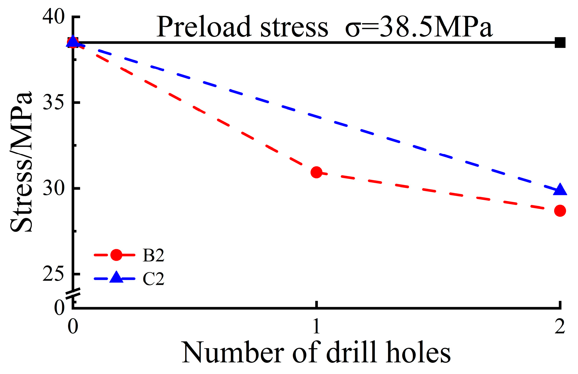
3.2. Evolution Characteristics of One-Off Pressure Relief Borehole Drilling

Figure 5 presents the stress–time curves of one-off pressure relief drilling. The stress gradually increased, with C32 having a shorter compaction stage and faster increase rate, indicating fewer internal pores. Upon reaching the preload stress, borehole drilling caused varying degrees of stress reduction. The stresses in C12, C22 and C32 decreased to 30.61 MPa, 29.85 MPa and 27.37 MPa, with reductions of 20.5%, 22.4% and 28.9%, respectively.
The samples failed upon reloading, exhibiting fluctuating and decreasing stress with visible crack expansion, compaction and re-expansion, unlike the brittle failure of the staged drilling samples. For single and double-borehole samples, axial pressure induced fractures at borehole edges propagating through the sample, causing failure. In the triple-borehole sample, the top borehole connected with the other two via penetrating cracks. Further propagation to the edges led to sample failure and the loss of load bearing capacity, as shown in Figure 6.
Let us take C32 as an example to analyze the stress evolution in one-off drilling. Initially, the stress gradually increased under axial compression. At 460 s, the stress reached the preload value, and then three sequential boreholes were drilled without interruption while maintaining the loading displacement. From 460 s to 644 s, the stress decreased by 28.9% to 27.37 MPa. It remained relatively stable from 645 s to 1667 s, suggesting the pressure relief limit had been reached. Reloading at 1667 s led to a sudden drop in stress, indicating violent crack expansion. The subsequent compaction increased the stress until failure. In the post-peak region, the sample showed features of ductile failure. The time from peak stress to final failure was 259 s, with large drops and small rises in between.
After the one-time drilling of pressure relief holes, the stresses of the samples showed different degrees of cliff-like drops, but the drop amplitudes were lower than those of staged drilling. This is believed to be because the one-time drilling led to concentrated stress and excessively rapid release. Upon reloading to failure, the samples exhibited fluctuating and decreasing stress ductile failure modes rather than brittle failure, which was due to the large number of cracks generated inside the samples during the one-time pressure relief. Analysis of sample C32: after pressure relief, the stress decreased by 28.9%, then stabilized. Upon reloading, large fluctuations of stress occurred, indicating the process of crack propagation, compaction, and re-propagation. Failure occurred after 259 s. For single-hole and double-hole samples, failure occurred at the edges of pressure relief holes, while for the triple-hole sample, failure occurred between the holes. This shows that the number and layout of pressure relief holes affect the failure modes of the samples. Overall, one-time pressure relief led to a large amount of crack generation and stress redistribution in the samples, making the failure more ductile but also decreasing the load bearing capacity, so caution should be exercised during the operation.

3.3. Test Result Comparison and Analysis

Figure 7 presents the stress evolution of staged pressure relief drilling under high stress. With increasing borehole quantity, the stress reductions were as follows: B11 decreased to 30.75 MPa, with a reduction of 20.1%; B21 decreased to 27.68 MPa, with a reduction of 28.1%; and B32 decreased to 25.15 MPa, with a reduction of 34.6%.
Figure 8 shows the stress changes in one-off drilling: the stress of C12 decreased from 38.50 MPa to 30.61 Mpa, with a reduction of 20.5%; the stress of C22 decreased from 38.50 Mpa to 29.85 Mpa, with a reduction of 22.4%; and the stress of C32 decreased from 38.50 MPa to 27.37 MPa, with a reduction of 28.9%.
Comparing the test results reveals that the pressure relief amplitude of B32 was 6.5% higher than that of B21, and that of B21 was 8.0% higher than that of B11; the pressure relief amplitude of C32 was 6.5% higher than that of C22, and that of C22 was 1.9% higher than that of C12. The stress–time curves indicate that the samples retained considerable strength after pressure relief and could still provide good load-bearing capacity. This suggests that, with a spacing of 40 mm and up to three boreholes, more boreholes lead to better pressure relief ahead of peak stress.
Figure 9 and Figure 10 present the stress changes for samples with the same number of boreholes but different drilling modes under uniaxial compression. For the two-borehole samples, the stress decreased to 27.68 MPa for B21 and 29.85 MPa for C22, with the pressure relief amplitude of staged drilling (B21) being 5.7% higher than that of one-off drilling (C22). As shown in Figure 9, the stresses were reduced to 25.15 MPa for B32 and 27.37 MPa for C32, giving a 5.7% higher relief amplitude for staged drilling (B32) over one-off drilling (C32). The results demonstrate that staged drilling is more effective than one-off drilling for the same number of pressure relief boreholes in sandstone samples under high stress, especially with more boreholes: the increased relief of three-hole samples was 1.9 times that of two-hole sample.
When the number of pressure relief holes increases, both staged drilling and one-time drilling lead to varying degrees of improvement in the stress drop amplitudes of the samples. This indicates that increasing the number of pressure relief holes is advantageous for enhancing the pressure relief effect. Under the same number of pressure relief holes, the stress drop amplitude of staged drilling is significantly higher than that of one-time drilling. For instance, the three-hole sample B32 has a drop amplitude of 34.6%, while C32 has 28.9%. This demonstrates that staged drilling provides better pressure relief than one-time drilling. It is analyzed that staged drilling can gradually release the internal energy stored in the rock, which facilitates the control of the pressure relief process. In contrast, one-time drilling tends to cause stress concentration and abrupt release. Under high stress conditions, the more pressure relief holes drilled sequentially, the more pronounced the improvement in pressure relief. The pressure relief amplitude increase of the three-hole sample is 1.9 times that of the two-hole sample. After reloading, the sample still possesses considerable load bearing capability, indicating the staged drilling of pressure relief holes can effectively reduce the stress level of the rock mass, given proper control over the number and layout of the holes. In summary, for rock masses under high stress, adopting the staged drilling of pressure relief holes and gradually increasing the hole quantity can achieve superior pressure relief effects, benefiting the stable control of the rock mass.

4. Numerical Simulation

4.1. Building of the Model

A FLAC3D model was built based on the sample dimensions, using the Mohr–Coulomb constitutive model. The model parameters are as follows: density 2700/(kg·m−3), bulk modulus 19.79/GPa, shear modulus 19.86/GPa, internal friction angle 34°, cohesion 4.8/MPa and tensile strength 6.4/MPa. The bottom boundary displacement was constrained, and 38.50 MPa vertical stress was applied in the Z direction. Circular boreholes with an 8 mm diameter and 80 mm depth were excavated in the model. The calculation convergence criteria required the unbalanced force ratio to reach 1 × 10⁻⁵.

4.2. The Analysis of Numerical Simulation Results Compared with Experimental Results

The borehole pressure relief effect in sandstone samples under high stress was simulated, obtaining the plastic zone evolution as shown in Figure 11. Taking B32 as an example, the plastic zone volume was extracted using the Fish language and compared with the stress changes.
As shown in Figure 11b, after calculating to equilibrium, two types of plastic zones were observed—occurred and occurring shear plastic zones. The minimum distance between the zones was 15 mm. Comparing the plastic zone clouds at each stage shows that the occurring shear plasticity was concentrated around the new borehole during drilling, while the small volume increased its concentration at the edges of previous boreholes. This indicates that the influence of new boreholes on previous plastic zones is minor at 40 mm spacing, with stable borehole-surrounding rock. It implies that, with increasing stress, cracks would propagate from the plastic zone edges to the sample boundaries, penetrating the boreholes and causing failure, consistent with experimental observations. Figure 11c shows a close relationship between pressure relief amplitude and plastic zone volume. For the first borehole, the volume was 17.06 cm3 with a stress of 29.94 MPa. For the second borehole, the volume increased to 29.29 cm3 with a stress of 26.70 MPa. For the third borehole, the volume reached 38.27 cm3 with a stress of 25.15 MPa. This demonstrates that more boreholes lead to larger plastic zone volumes and greater stress reductions under high stress, indicating better pressure relief. The occurring shear plastic zone volumes for B32 were 16.28 cm3, 11.55 cm3 and 8.98 cm3 for each stage, with corresponding stress reductions of 22.2%, 6.6% and 5.8%. This suggests that the single-borehole plastic zone volume is negatively correlated with borehole quantity, and the relief effect diminishes gradually.

5. Discussion

The energy transformation of rock samples under uniaxial compression can be divided into four stages—compaction energy input, elastic energy accumulation, crack expansion energy dissipation and post-peak failure energy release [25]—as shown in Figure 12.
This study focuses on pre-peak borehole pressure relief in sandstone. Since the preload stress is much lower than the failure stress of intact samples, there is no yielding before drilling relief boreholes. Thus, the energy process involves only compaction input and elastic accumulation. The total energy absorption increases continuously under loading, with most of the energy stored as elastic strain energy. At this point, the sample elastic strain energy is the peak elastic strain energy without the limit being reached, so macroscopic failure does not occur [26].
Drilling the first relief borehole causes mechanical disturbances that induce microcracks in the surrounding rock. The released elastic strain energy promotes microcrack growth. Crack propagation expands the plastic zone, decreasing the stress [11]. After the first borehole, loading stops; therefore, the lost elastic strain energy cannot be replenished without external work. The remaining elastic energy is insufficient to extend the cracks further, and the sample stabilizes. Now, the retained elastic strain energy is less than that of intact samples. The second borehole provides less driving energy for microcrack growth, with a smaller plastic zone increase and stress reduction compared to the first stage. The third stage works on the same principle.
Xie Heping et al. [27] stated that energy dissipation is directly related to strength loss and that the original strength decay reflects the dissipated energy amount. The test results show that the pressure relief amplitude in the first stage is larger than that in the second stage, which is larger than that in the third stage under the same energy input. This demonstrates decreasing energy dissipation over the stages. The efficiency of single-borehole pressure relief ahead of peak stress decreases with more drilling events, indicating limited relief and close correlation with retained elastic energy. Comparing staged and one-off drilling reveals that more boreholes lead to greater total unloading amplitudes, suggesting increased total energy dissipation. Staged drilling has slower dissipation over longer cycles but larger relief amplitudes, reducing impact tendencies. One-off drilling dissipates energy faster over shorter cycles and is therefore suitable for rock burst hazards.
Due to experimental constraints and the specificity of pressurized borehole tests, this study did not accurately calculate the dissipated energy values and input energy differences between drilling events. Further research is needed to obtain accurate energy quantifications.

6. Conclusions

The following conclusions were obtained from the borehole pressure relief experiments on sandstone samples under high stress:
(1)
For non-prefabricated boreholes in sandstone samples under high stress, staged drilling resulted in pressure relief amplitudes of 20.1%, 28.1% and 34.6%, while one-off drilling led to relief amplitudes of 20.5%, 22.4% and 28.9%. The pressure relief effect is positively correlated with the number of boreholes. Staged drilling is more effective than one-off drilling.
(2)
The numerical simulation results show that the surrounding rock forms plastic zones under stress. In staged drilling tests with 40 mm spacing, the influence of new boreholes on existing plastic zones is minor, with each stage dominated by the individual borehole plasticity.
(3)
Combining the results of the lab tests and simulations shows that the volume of staged drilling plastic zones is an important factor influencing pressure relief. The volumes are 16.2808 cm3, 11.5506 cm3 and 8.9823 cm3 for each stage, with corresponding stress reductions of 22.2%, 6.6% and 5.8%. This indicates that the single-borehole relief amplitude is negatively correlated with the number of existing boreholes.

Author Contributions

Conceptualization, J.J. and W.W.; methodology, X.L.; software, X.C.; validation, W.W., X.C. and L.H.; formal analysis, X.L.; investigation, X.C.; resources, J.J.; data curation, X.L.; writing—original draft preparation, X.L.; writing—review and editing, J.J.; visualization, X.C.; supervision, W.W.; project administration, W.W.; funding acquisition, W.W. All authors have read and agreed to the published version of the manuscript.

Funding

This study was supported by the Program for National Major Achievement Cultivation, Theory and Key Technology of Natural Gas and Coal Resources Cooperative Mining, NSFRF230202; Theory and Technology of Natural Gas-Coal-Uranium Mining Synergy; Research on the Theory and Key Technology of Coordinated Natural Gas and Coal Mining, 23HASTIT011; Research on the Mechanism of Coordinated Coal and Natural Gas Exploitation and Disaster Warning in Ordos Basin, T2022-2; National Natural Science Foundation of China funded project (52174109).

Data Availability Statement

Due to the nature of this research, participants of this study did not agree for their data to be shared publicly, so supporting data is not available.

Conflicts of Interest

The authors declare no conflict of interest.

References

  1. Wang, J.Y.; Hu, S.B.; Pang, Z.H.; He, L. Estimate of geothermal resources potential for hot dry rock in the continental area of China. Sci. Technol. Rev. 2012, 30, 25–31. [Google Scholar]
  2. Xu, T.F.; Zhang, Y.J.; Zeng, Z.F.; Bao, X. Technology progress of enhanced geothermal system (hot dry rock). Sci. Technol. Rev. 2012, 30, 42–45. [Google Scholar]
  3. Brown, D. The US hot dry rock program-20 years of experience in reservoir testing. In Proceedings of the World Geothermal Congress, Florence, Italy, 18–31 May 1995; pp. 2607–2611. [Google Scholar]
  4. Lu, C.; Wang, G.L. Current status and prospect of hot dry rock research. Sci. Technol. Rev. 2012, 33, 13–21. [Google Scholar]
  5. Zhai, H.Z.; Su, Z.; Wu, N.Y. Development experiences of the Soultz enhanced geothermal systems and inspirations for geothermal development in China. Adv. New Renew. Energy 2014, 2, 286–294. [Google Scholar]
  6. Lu, Y.; Zou, X.; Liu, C.; Xing, S.J. Technology of Digging Stress-Relax Entry by the Roadside and Its Application. J. Min. Saf. Eng. 2006, 23, 329–332. [Google Scholar]
  7. Guo, B.; Lu, T. Analysis of Floor Heave Mechanism and Cutting Control Technique in Deep Mines. J. Min. Saf. Eng. 2008, 25, 91–94. [Google Scholar]
  8. Wang, L.; Jiang, F.; Yu, Z. Similar Material Simulation Experiment on Destressing Effects of the Deep Thick Coal Seam with High Burst Liability after Mining Upper and Lower Protective Seams. Chin. J. Geotech. Eng. 2009, 31, 442–446. [Google Scholar]
  9. Song, X.; Zuo, Y.; Zhu, W. Effect of Lateral Pressure Coefficients on Pressure-Released Hole Combined Support with Rockbolt under Dynamic Disturbance. Chin. J. Undergr. Space Eng. 2013, 9, 1076–1081. [Google Scholar]
  10. Ortlepp, P.W.D.; Stacey, T.R. Rockburst Mechanisms in Tunnels and Shafts. Tunn. Undergr. Space Technol. 1994, 9, 59–65. [Google Scholar] [CrossRef]
  11. Kaiser, P.; Yazici, S.; Maloney, S. Mining-Induced Stress Change and Consequences of Stress Path on Excavation Stability—A Case Study. Int. J. Rock Mech. Min. Sci. 2001, 38, 167–180. [Google Scholar] [CrossRef]
  12. Liu, H.; He, Y.; Xu, J.; Han, L.-J. Numerical Simulation and Industrial Test of Boreholes Distressing Technology in Deep Coal Tunnel. J. China Coal Soc. 2007, 32, 33–37. [Google Scholar]
  13. Zhang, Y.; Hao, F.; Liu, C.; Liu, W.J. Borehole Relief Range Considering Plastic Softening and Dilatancy of Coal. J. Liaoning Tech. Univ. 2013, 1599–1604. [Google Scholar]
  14. Zheng, H.; Wang, M.; Xu, S. Research on Surrounding Rock Pressure Relief in Deep Roadway by Borehole and Its Control Technology. Min. Saf. Environ. Prot. 2014, 51–55. [Google Scholar]
  15. Zhu, S.; Jiang, F.; Shi, X.; Sun, G.; Zhang, Z.; Cheng, X.; Zhang, H. Energy Dissipation Index Method for Determining Rockburst Prevention Drilling Parameters. Rock Soil Mech. 2015, 36, 2270–2276. [Google Scholar]
  16. Wang, S.; Pan, J.; Liu, S.; Xia, Y.X.; Gao, X.J. Evaluation Method for Rockburst-Preventing Effects by Drilling Based on Energy-Dissipating Rate. J. China Coal Soc. 2016, 41, 297–304. [Google Scholar]
  17. Wang, M.; Wang, X.; Xiao, T. Borehole Destressing Mechanism and Determination Method of Its Key Parameters in Deep Roadway. J. China Coal Soc. 2017, 42, 1138–1145. [Google Scholar]
  18. Jia, C.; Jiang, Y.; Zhang, X.; Wang, D.; Luan, H.; Wang, C. Laboratory and Numerical Experiments on Pressure Relief Mechanism of Large-Diameter Boreholes. Rock Soil Mech. 2017, 39, 1115–1122. [Google Scholar]
  19. Qin, Z. Study of Pressure Relief with Large Diameter Drilling Hole and Results Verified. Coal Min. Technol. 2018, 23, 82–85. [Google Scholar]
  20. Ma, B.W.; Deng, Z.G.; Zhao, S.K.; Li, S.G. Analysis on Mechanism and Influencing Factors of Drilling Pressure Relief to Prevent Rock Burst. Coal Sci. Technol. 2020, 48, 35–40. [Google Scholar]
  21. Zhao, Z.; Zhang, X.; Li, X. Experimental Study of Stress Relaxation Characteristics of Hard Rocks with Pressure Relief Hole. Rock Soil Mech. 2019, 40, 170–177. [Google Scholar]
  22. Lin, P.; Wong, R.H.; Tang, C. Experimental Study of Coalescence Mechanisms and Failure under Uniaxial Compression of Granite Containing Multiple Holes. Int. J. Rock Mech. Min. Sci. 2015, 77, 313–327. [Google Scholar] [CrossRef]
  23. Zhao, T.-B.; Guo, W.-Y.; Yu, F.-H.; Tan, Y.-L.; Huang, B.; Hu, S.-C. Numerical Investigation of Influences of Drilling Arrangements on the Mechanical Behavior and Energy Evolution of Coal Models. Adv. Civ. Eng. 2018, 2018, 1–12. [Google Scholar] [CrossRef]
  24. Huang, B.; Guo, W.-Y.; Fu, Z.-Y.; Zhao, T.-B.; Zhang, L.-S. Experimental Investigation of the Influence of Drilling Arrangements on the Mechanical Behavior of Rock Models. Geotech. Geol. Eng. 2018, 36, 2425–2436. [Google Scholar] [CrossRef]
  25. Zhang, L.; Gao, S.; Wang, Z. Rock Elastic Strain Energy and Dissipation Strain Energy Evolution Characteristics under Con-ventional Triaxial Compression. J. China Coal Soc. 2014, 39, 1238–1242. [Google Scholar]
  26. Zhao, Z.; Lu, R.; Zhang, G. Analysis on Energy Transformation for Rock in the Whole Process of Deformation and Fracture. Min. Res. Dev. 2006, 26, 8. [Google Scholar]
  27. Xie, H.; Ju, Y.; Li, L. Criteria for Strength and Structural Failure of Rocks Based on Energy Dissipation and Energy Release Principles. Chin. J. Rock Mech. Eng. 2005, 24, 3003–3010. [Google Scholar]
Figure 1. RMT-150-B electrohydraulic servo rock test system.
Sustainability 15 15557 g001
Figure 2. Sample loading diagram.
Sustainability 15 15557 g002
Figure 3. Flowchart of the experiment.
Sustainability 15 15557 g003
Figure 4. The stress-time curve for the staged drilling of the pressure relief hole of the specimen.
Sustainability 15 15557 g004
Figure 5. The stress-time curve for one drilling of the specimen pressure relief hole.
Sustainability 15 15557 g005
Figure 6. Specimen loading diagram.
Sustainability 15 15557 g006
Figure 7. The variation in stress in the specimen pressure relief hole drilled in stages.
Sustainability 15 15557 g007
Figure 8. The variation of stress in one drilling of the specimen pressure relief hole.
Sustainability 15 15557 g008
Figure 9. Characteristics of variation in pressure relief stress for a sample with two pressure relief holes.
Sustainability 15 15557 g009
Figure 10. Characteristics of variation in pressure relief stress for a sample with three pressure relief holes.
Sustainability 15 15557 g010
Figure 11. Characteristic diagram of the plastic zone of the sample. (a) B32 stress–time curve. (b) Cloud view of the plastic zone of the specimen. (c) B32 plastic zone versus stress relationship.
Sustainability 15 15557 g011aSustainability 15 15557 g011b
Figure 12. Schematic diagram of energy evolution during rock deformation and failure.
Sustainability 15 15557 g012
Table 1. Specimen parameters.
GroupNo.Unloader
Hole
Quantity
Length
/mm
Width
/mm
Height
/mm
Notes
IA11/80.0579.9680.02Full specimens
A12/80.8980.7379.80
IIB11180.0579.8380.02Staged drilling of pressure relief holes
B12180.2880.1480.32
B21280.2279.7780.19
B22279.9281.1380.21
B31380.1380.2180.17
B32380.0879.8779.79
IIIC11180.8180.8379.87Pressure relief holes
One drilling event
C12180.1280.0779.92
C21279.6579.7680.23
C22280.2180.1779.89
C31380.0780.2680.18
C32379.9380.1280.08
Disclaimer/Publisher’s Note: The statements, opinions and data contained in all publications are solely those of the individual author(s) and contributor(s) and not of MDPI and/or the editor(s). MDPI and/or the editor(s) disclaim responsibility for any injury to people or property resulting from any ideas, methods, instructions or products referred to in the content.

