Article

Simulation and Experiment of Fertilizer Discharge Characteristics of Spiral Grooved Wheel with Different Working Parameters

College of Mechanical and Electrical Engineering, Gansu Agricultural University, Lanzhou 730070, China
*
Authors to whom correspondence should be addressed.
Sustainability 2023, 15(14), 11309; https://doi.org/10.3390/su151411309
Submission received: 25 June 2023 / Revised: 13 July 2023 / Accepted: 18 July 2023 / Published: 20 July 2023
(This article belongs to the Special Issue Innovation and Technology for Sustainable Agriculture)

Abstract

:
Fertilizer particles have strong hygroscopicity and agglomeration often occurs during their storage, which leads to a blocked phenomenon during the operation of the external grooved wheel fertilizer discharger. In this study, the bond model of fertilizer block was constructed based on the discrete element method (DEM) to further explore the effect of different working parameters of the spiral grooved wheel on the fertilizer discharge characteristics. According to the Box–Behnken experimental design principle, a three-factor and three-level simulation experiment was carried out with the factors of grooved wheel speed, grooved wheel section shape, and spiral rise angle. The simulation results showed the variation coefficient of fertilizer uniformity was affected, from important to secondary, mainly by the rotating speed of the grooved wheel, the cross-sectional shape of the grooved wheel, and the spiral rise angle. The broken rate of fertilizer block bond was affected, from important to secondary, mainly by the spiral rise angle, the cross-sectional shape of the grooved wheel, and the rotational speed of the grooved wheel. The optimal combination of working parameters was obtained by optimizing and analyzing the data; the rotating speed of the grooved wheel was 21 r/min, the scoop section, and the spiral rise angle was 70°. Under the best working parameters, the variation coefficient of fertilizer uniformity was 8.56%, and the broken rate of fertilizer block bond was 97.67%. The validation experiment results showed that the variation coefficient of fertilizer uniformity was 9.23%, the broken rate of fertilizer block bond was 94.28%, and the relative data error was less than 10%. The experimental results are close to the simulation results. The research results can provide a reference for the structural design and parameter optimization of spiral grooved wheel fertilizer discharger.

1. Introduction

Chemical fertilizer is high in nutrients and demonstrates a strong water absorption and easy adhesion [1]. It is widely used in agricultural production and is an important nutrient source for crop growth and development [2]. According to statistics, in 2021, China’s agricultural chemical fertilizer production reached 55.43 million tons, and the application amount exceeded 52.51 million tons. China has become one of the largest fertilizer production and application countries in the world [3]. The rainfed agriculture systems in the northwest of China mostly uses solid fertilizer, which has strong water absorption and is easy to agglomerate in daily storage. When applying fertilizer with an external grooved wheel fertilizer discharger (EGWFD), it is easy to cause the accumulation of fertilizer in the storage box and block the fertilizer discharge pipe, which leads to fertilizer leakage, affecting crop growth [4].
The EGWFD has good stability and uniformity during operation. It can adjust the amount of fertilizer discharged by changing the rotating speed and working length of the grooved wheel (GW). Due to its simple structure, high reliability, and low cost, it is widely used in field fertilization [5,6]. Relevant scholars have carried out research on the EGWFD. In terms of the structural design of GW, Dun et al. [7] designed a GW-type fertilizer blending device and optimized the structural parameters to study the layered fertilizer application technology. Song et al. [8] designed the shape and structural parameters of the GW and studied the EGWFD device suitable for fertilization using a unmanned aerial vehicle. Sugirbay et al. [9] designed an outer GW with roller columns regularly distributed on the surface. This structure has good uniformity and stability in the process of fertilizer discharge and is also suitable for damp particles. In the study of fertilizer discharge stability, Zhang et al. [10] built a generalized regression neural network prediction model of fertilizer discharge amount with the opening of the fertilizer discharge port and the rotation speed of the screw external GW fertilizer discharger as variables and explored the influence of different variables on the fertilizer discharge stability. Lv et al. [11] used the self-developed discrete element method (DEM) software to analyze the fertilizer amount of the EGWFD. When the working length of the GW remains unchanged, the fertilizer amount will increase with the increase in the GW speed; When the GW speed is fixed, with the increase in the working length of the GW, the amount of fertilizer discharged increases slowly at the beginning and then increases rapidly. Zeng et al. [12] studied the stability of the EGWFD in the process of fertilizer filling. In terms of theoretical analysis, Sun et al. [13] examined how the outer GW structure easily damaged the fertilizer during the process of fertilizer discharge. They used simulation methods to study the speed and stress changes of particles in the process of fertilizer discharge. Through simulation, regression model and experimental analysis, they obtained the best fertilizer operation parameters.
In summary, the above research involves the structural parameters, working parameters, and fertilizer discharging performance of the -discharging device. Most of which are of straight GW structure, less of spiral structure. In addition, it does not involve the broken fertilizer performance and fertilizer discharging uniformity of the GW fertilizer discharging device, and it does not consider the blockage of the fertilizer discharging pipe. Therefore, it is of practical significance to explore the influence of the structural parameters of the spiral GW on broken fertilizer performance and uniformity of the fertilizer discharge. In this study, Urea granules are taken as research objects. Bond model of DEM is established according to physical characteristics. The mathematical model between different GW structures, broken fertilizer performance, and fertilizer discharge uniformity is built using a Box–Behnken experiment scheme. The action rules between different variables and response indicators are obtained through response surface method analysis. Finally, bench verification experiments are conducted. The research results provide a reference for the structural design and optimization of the spiral grooved wheel fertilizer discharger (SGWFD).

2. Materials and Methods

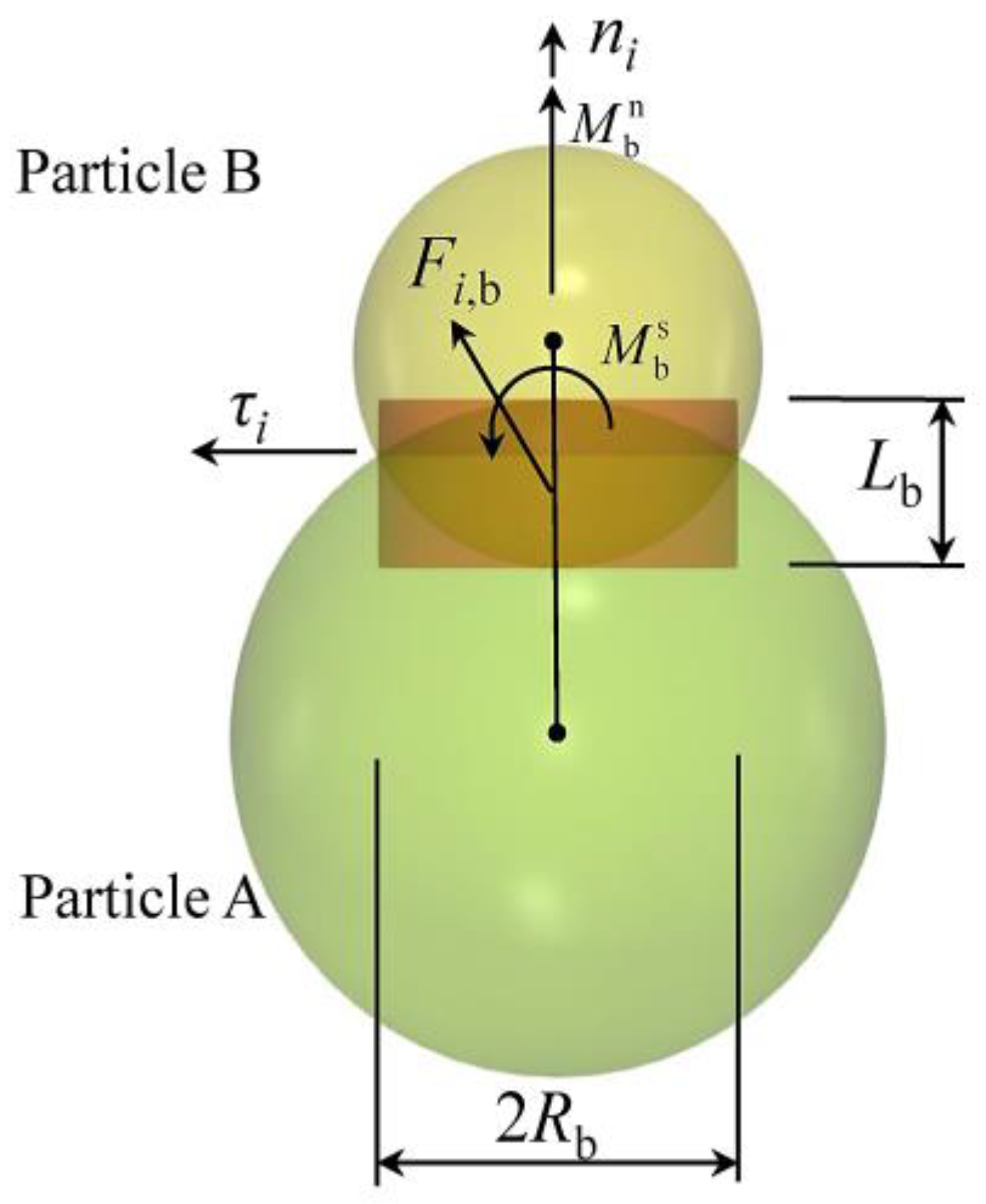
2.1. Bond Model of DEM
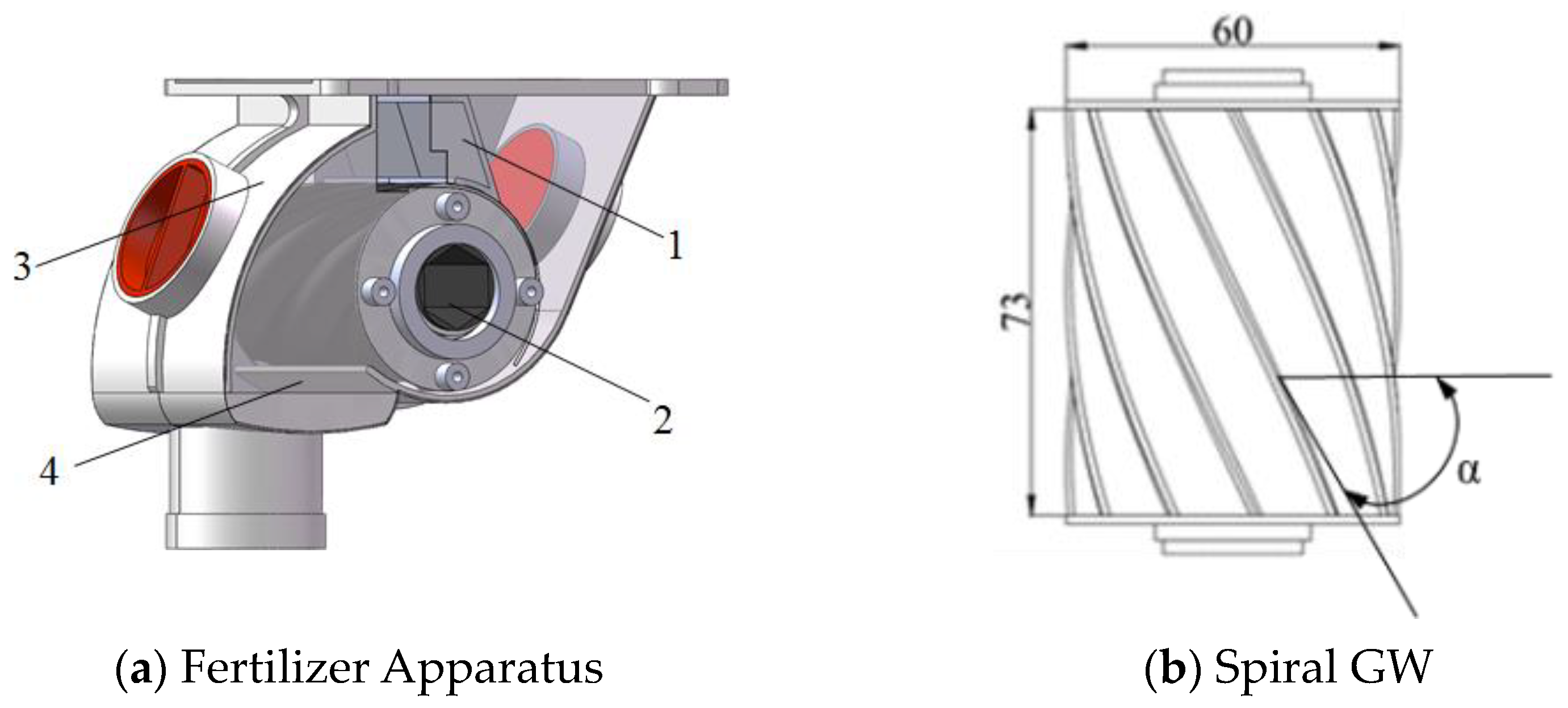
Since Cundall and Strack proposed the DEM in 1979, it has been widely used in various industries [14]. This algorithm is a time driven efficient numerical simulation method based on soft sphere model [15], which can accurately predict the movement behavior of powder particles and granular materials. The application of DEM has deepened human understanding of the movement law of bulk materials in agricultural production.
Bond model is often used in the study of material breakage [16]. Figure 1 is a schematic diagram of bond model of DEM. Two particles bonded at the contact point. The bonding characteristics are equivalent to a group of springs on the circular section of the particles. The macro mechanical characteristics are characterized by micro forces and moments at the contact point. In the simulation, the force, moment, displacement and velocity between particles are calculated using Newton’s second law. When the bond between particles is broken, the force and moment will follow Hertz–Mindlin (no slip) contact model [17], and the bond property between particles will disappear.
Without considering the air resistance, the main field force on the particles is gravity. The motion control equations are as follows [18]:
m i d ν i d t = ( F i j n + F i j t ) + G i
I i d ω i d t = ( R i × F i j t τ i j r )
where ν i is the linear velocity of particle i, m/s; ω i is the angular velocity of particle i, rad/s; G i is the gravity of particles, N; I i is the moment of inertia of the particle, kg·m2; F i j n is the normal force between particles, N; F i j t is the tangential force between particles, N; R i is the distance from the center of mass to the contact point when the tangential force F i j t acting on the particles, mm; τ i j r is the rolling friction torque, N·m.

2.2. SGWFD 3D Model

The SGWFD is mainly composed of brush, spiral GW, fertilizer box, fertilizer discharge tongue, etc., as shown in Figure 2a. During fertilization, the spiral GW is driven by the motor to rotate. After filling the groove of the GW, the fertilizer particles will be sent to the fertilizer discharge tongue, and then flow into the fertilizer discharge pipe to complete the whole fertilizer discharge process. The diameter of the spiral GW in the study is 60 mm, the axial length is 73 mm, and the spiral lift angle α is the included angle between the tangent of the helix and the plane perpendicular to the thread axis (Figure 2b).
The amount of fertilizer discharged is very important to crop growth. If too little fertilizer is applied to a single crop, the crop will not obtain enough nutrients, which will affect its growth and development; However, excessive fertilization will cause seedling burning. The fertilizer discharge quantity q of the spiral fertilizer discharger GW rotating for one cycle can be calculated by the equation as follows:
q = π d L γ ( α 0 f q t + λ )
where d is the outer diameter of spiral GW, mm; L is the effective working length of the spiral GW, mm; γ is the fertilizer density, kg/m3; f q is the sectional area of a single spiral groove, mm2; t is the pitch of spiral groove, mm; α 0 is the fertilizer filling coefficient in the spiral groove; λ is the driving coefficient of fertilizer outside the groove of the GW.

2.3. Construction of Fertilizer Block Model and Parameters Calibration

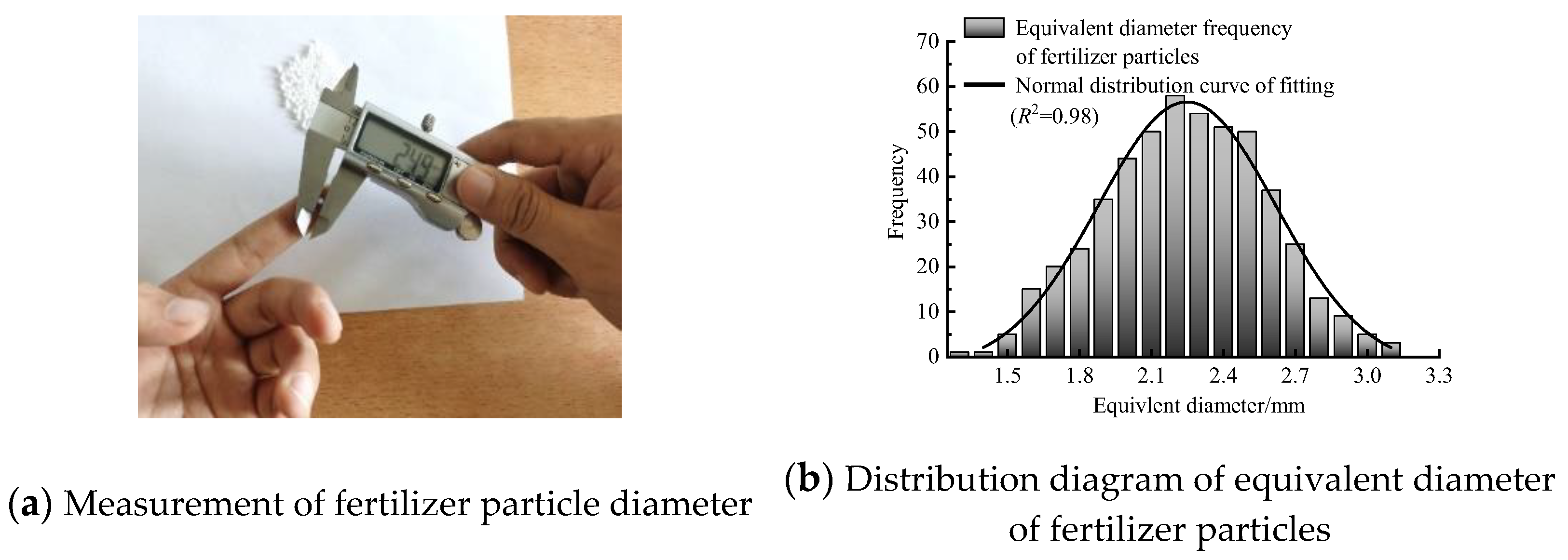
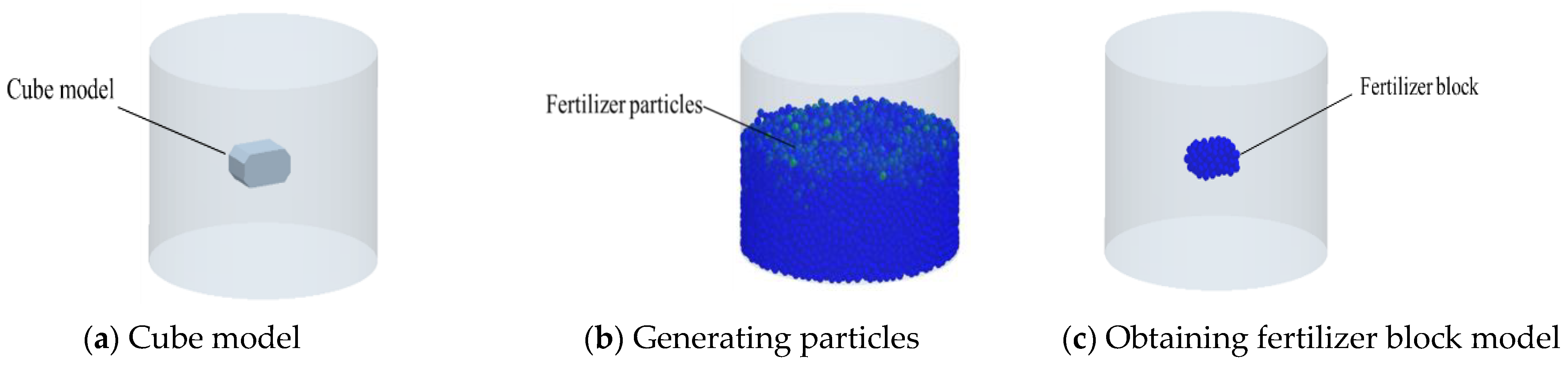
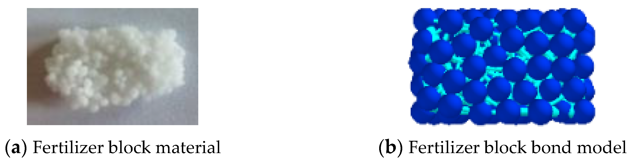
2.3.1. Model Construction of Fertilizer Block

Fertilizer is one of the necessary materials for achieving high yield in crops, and the shapes of different types of fertilizers may vary, but they are generally spherical in shape. This study selected Urea (Carboamide) fertilizer as the research object, highlighting the research ideas and methods, and providing reference for the study of other related fertilizer particles. Urea, as a kind of nitrogen fertilizer, has strong hygroscopic characteristics and is widely used as base fertilizer or top dressing in agricultural production. In this study, the Urea fertilizer produced by Ruixing Chemical Co., Ltd. (Taian, China) were selected as the research object, and a digital vernier caliper (with an accuracy of 0.01 mm) was used to measure the shape size (length, width, and height) of 500 randomly selected fertilizer particles in three axes (Figure 3a). According to Equation (3), the equivalent diameter of a single fertilizer particle could be obtained, and the equivalent diameter of all measured samples could be summarized into a columnar figure [19], as shown in Figure 3b. It can be seen from the figure that the determination coefficient R2 of the fitting curve is 0.98, indicating that the equivalent diameter of fertilizer particles has good agreement with the normal distribution law, and most of the fertilizer particle diameters are concentrated in the middle area. Therefore, in this study, the shape of fertilizer particles is simplified as sphere, and the unified diameter of particles are the equivalent diameter. Take the average of the overall dimensions of all experimented particles, and the length, width, and height are 2.314 mm, 2.172 mm, and 2.121 mm, respectively. It can be concluded that the equivalent diameter D of fertilizer particles is 2.201 mm according to Equation (4). In addition, the data are substituted into Equation (5) to obtain the sphericity of fertilizer particles φ is 95.12%, indicating that Urea particles have good sphericity, which further proves that it is feasible to treat fertilizer particles with equal particle size in the study.
D = L W T 3
φ = D L
where L, W, and T are the length, width, and height of Urea particles, respectively, in mm.
The fertilizer blocks collided with the wall of the fertilizer discharger at the early stage of breakage and were initially broken into smaller blocks, resulting in a large number of small blocks during the fertilization process. Therefore, this study mainly considers the breakage process of small-sized fertilizer blocks while taking into account the time-consuming simulation calculation. First of all, the 16 mm × 10 mm × 8 mm (length, width, and height) of cube model was established in SolidWorks (3D CAD software, Concord, MA, USA). Then, the geometric model was imported into the EDEM software (Engineering discrete element method, Altair Engineering, Inc., Troy, MI, USA). The falling rain method was used to fill the cube model with particles with a diameter of 2.201 mm. The filled fertilizer block contained 182 particles in total. The filling process of the fertilizer block model is shown in Figure 4.

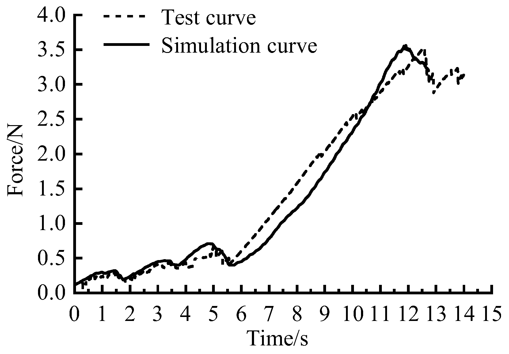
2.3.2. Calibration of Fertilizer Block Bond Model Parameters

At present, there is no unified method for the parameter calibration of bond model [20]. According to the literature, most scholars use the phenomenological simulation method for parameters calibration [20,21]. If comparison between simulation experiment and physical experiment of the research process have the same change in apparent characteristics, and the trend of mechanical characteristic curve is similar, the simulation parameters are considered capable of describing the physical characteristics of the material. In this study, according to ASAE S368.4 DEC2000 (R2008) standard [22], uniaxial compression method was used to calibrate the parameters of the fertilizer bond model. Bond model mainly includes 5 parameters, normal stiffness coefficient per unit area, tangential stiffness coefficient per unit area, critical normal stress, critical tangential stress, and bonding radius; the combination of these parameters can realize different macroscopic phenomena.
Before the experiment, the shape dimension 16 mm × 10 mm × 8 mm (length, width and height) was selected for the fertilizer block as experiment material from naturally stacked fertilizer bags (Figure 5a). Firstly, the TA.XT plus texture analyzer (with force accuracy of 0.1 g) was used to conduct uniaxial compression experiment on the fertilizer block. The acceleration speed of the experiment indenter was 5 mm/min, and the force and time change data were recorded automatically. Secondly, uniaxial compression simulation was carried out on the fertilizer block (Figure 5b) with bond model added, and bond parameters were obtained by observing and comparing the apparent characteristics of fertilizer block breakage and the force and time change data. The experiment was conducted indoors, with an ambient temperature of 25 °C and a humidity of 48%. Figure 6 shows the comparison between simulation and experiment data of fertilizer block under uniaxial compression. It can be seen from the figure that the trend of simulation curve and experiment curve is approximately coincident, and the simulation data and experiment data are close at the same time. Therefore, it can be considered that the bond parameters used in simulation can truly simulate the mechanical properties of the fertilizer block. The specific bond model parameters are shown in Table 1.

2.4. Simulation Parameter Setting and Analysis Method

2.4.1. Parameter Setting

The fertilizer discharger and its main components in this study are made of biodegradable polylactic acid (PLA). Through consulting the literature [23,24], the contact mechanical parameters between Urea fertilizer, PLA material, and the ground are shown in Table 2. In the simulation, the Poisson’s ratio of fertilizer particles is set to 0.25, and the Poisson’s ratio of PLA is set to 0.43; The elastic modulus of fertilizer particles is 8.55 × 10⁷ Pa, PLA elastic modulus is 1.3 × 10⁹ Pa; The density of fertilizer particles is 1320 kg/m3, and the density of PLA is 1240 kg/m3. The GW speed is set according to the data in the experiment plan, and the simulation time step is 2 × 10⁻⁶ s; the total simulation time is 10 s. In order to improve the simulation speed and reduce the amount of simulation data, the fertilizer discharger generates a total of 20 fertilizer blocks.

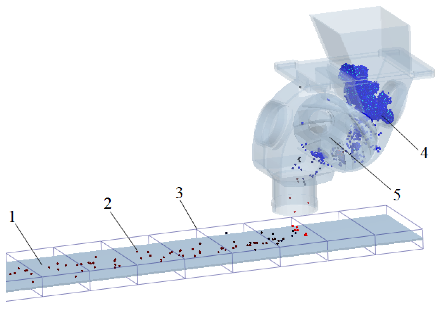
2.4.2. Analysis Method

According to the principle of relative motion of objects, the ground motion speed is set to 0.75 m/s in the simulation, and the fertilizer discharger is fixed. The movement track of fertilizer during falling is not considered in the simulation, so the vertical height of the lower end of the fertilizer discharger from the ground is set as 30 mm. The ground is 400 mm wide and 2 m long. In order to facilitate data analysis after simulation, a data statistics area is established every 200 mm along the forward direction of the ground. Figure 7 is the schematic diagram of fertilizer particle data statistics area.
In order to accurately analyze the fertilizer discharge uniformity and fertilizer crushing effect of the spiral fertilizer discharger under different groove wheel structure parameters, this study refers to the Technical Specifications for Quality Price of Fertilizer Machinery (NY/T 1003-2006) [25] and takes the variation coefficient of fertilizer discharge uniformity and the broken rate of fertilizer block bond as the evaluation index of the fertilizer discharge performance of the spiral fertilizer discharger.
The variation coefficient of fertilizer discharge uniformity is mainly used to measure the difference of fertilizer discharge in the range of equal spacing in the forward direction of the fertilizer discharge device and is one of the indicators evaluating the stability of the fertilizer discharge device. In the study, it is assumed that there are n statistical regions, in which the total mass of fertilizer in the ith region is mi, from which the variation coefficient of fertilizer discharge uniformity can be calculated σ [26] using the following equations:
m ¯ = 1 n m i
s = ( m i m ¯ ) 2 n 1
σ = S m ¯ × 100 %
where m ¯ is average mass of fertilizer in each interval, g; m i is the total mass of fertilizer in the ith area, g; n is the number of statistical areas set, n = 40 in this study; S is the standard deviation of the total mass of fertilizer particles, g; σ is the variation coefficient of fertilizer discharge uniformity.
The broken rate of fertilizer block bond is an index to evaluate the broken degree of fertilizer block. When the broken rate of bond is high, it indicates that the fertilizer block is fully broken; On the contrary, the broken rate of bond is low, it indicates that there are many unbroken fertilizer blocks in the simulation. Therefore, the broken rate of bond ε can be calculated as follows:
ε = M m M × 100 %
where M is the total mass of fertilizer block, g; m is the sum of the mass of single fertilizer particle after broken, g.

2.5. Experiment Scheme

The Box–Behnken experiment design scheme [27,28,29] can achieve the purpose of data analysis with less experiment times. In the study, according to the working principle of the SGWFD, the GW speed (X1), GW section shape (X2) and spiral rise angle (X3) were selected as the experiment factors, and the variation coefficient of fertilizer discharge uniformity (Y1) and the broken rate of fertilizer bond (Y2) were taken as the response indicators, and the experiment level code was shown in Table 3. Among them, the rotating speed range of the GW is 15~25 r/min, the sectional shape of the GW is designed into three shapes: arc shape, scoop shape, and trapezoid shape (Figure 8). The spiral rising angle is 60~70°.

3. Results

Figure 9 shows the simulation results at different times during the operation of the SGWFD. When t = 0.12 s, fertilizer block particles are generated in the calculation domain, and the falling speed is 0.6 m/s (Figure 9a). When t = 3.15 s, the fertilizer block has complete contacts with the fertilizer box and spiral GW (Figure 9b) and gradually breaks. When t = 6.7 s, the fertilizer block is driven by the spiral GW and crushed in a large area by extrusion. The number of broken bonds in the calculation domain increases sharply (Figure 9c). When t = 10.0 s, most of the fertilizer blocks are broken, and the fertilizer particles are discharged from the fertilizer discharge pipe driven by the spiral GW (Figure 9d). In the study, multi-factor and multi-level simulation experiments will be carried out by adjusting the working parameters and structural parameters of the GW according to the experiment scheme.
According to the determined experiment factors, each level is combined to form 17 groups of experiments. The statistical results of experiment data are shown in Table 4 (X1, X2, and X3 are the coded values of experiment factors, and Y1 and Y2 are the response indicators). The experiment results are analyzed via Design Expert 10.0 software (Minneapolis, MN, USA).

3.1. Establishment and Experiment of Regression Model

The variance analysis of the regression model (Table 5) was conducted for the variation coefficient of fertilizer discharge uniformity (Y1) and broken rate of fertilizer bond (Y2), and the quadratic regression models of Y1 and Y2 were obtained as follows:
Y 1 = 8.10 1.20 X 1 + 0.34 X 2 + 0.31 X 3 + 2.60 X 1 2 + 0.74 X 2 2 + 0.29 X 3 2 + 0.21 X 1 X 2 0.52 X 1 X 3 0.12 X 2 X 3
Y 2 = 96.46 0.25 X 1 0.49 X 2 + 1.39 X 3 0.32 X 1 2 0.095 X 2 2 0.44 X 3 2 0.0075 X 1 X 2 0.23 X 1 X 3 0.18 X 2
It can be seen from Table 5 that the quadratic regression model of the variation coefficient of fertilizer discharge uniformity p < 0.0001 indicates that the regression model is extremely significant; for the misfit item p > 0.05, the misfit is not significant, indicating that the quadratic regression equation fitted by the model can correctly reflect the relationship between the variation coefficient of fertilizer discharge uniformity Y1 and X1, X2, X3, and the model can well predict the variation coefficient of fertilizer discharge uniformity. The primary terms X1, X2, and X3 of the model have significant effects; The influence of secondary terms X12 and X22 is extremely significant, that of X32 is significant, that of interactive terms X1X3 is extremely significant, and that of other items is not significant. According to the regression coefficient of each factor in the model, the primary and secondary order of the influence of each factor on the fertilizer discharge variability coefficient can be obtained as X1, X2, and X3, that is, the GW speed, the GW cross-sectional shape, and the spiral lift angle.
At the same time, the quadratic regression model of the broken rate of fertilizer block is p < 0.0001, which shows that the regression model is very significant; The misfit term p > 0.05, the misfit is not significant, indicating that the quadratic regression equation fitted by the model can correctly reflect the relationship between the broken rate of fertilizer block Y2 and X1, X2, X3, and the regression model can well predict the broken rate of fertilizer block. The primary items X1, X2, and X3 of the model have extremely significant effects, the secondary item X32 has extremely significant effects, X12 has significant effects, and the other items are not significant. According to the regression coefficient of each factor in the model, the primary and secondary order of the influence of each factor on the bond fracture rate is X3, X2, X1, that is, the spiral rise angle, the section shape of the GW, and the GW speed.

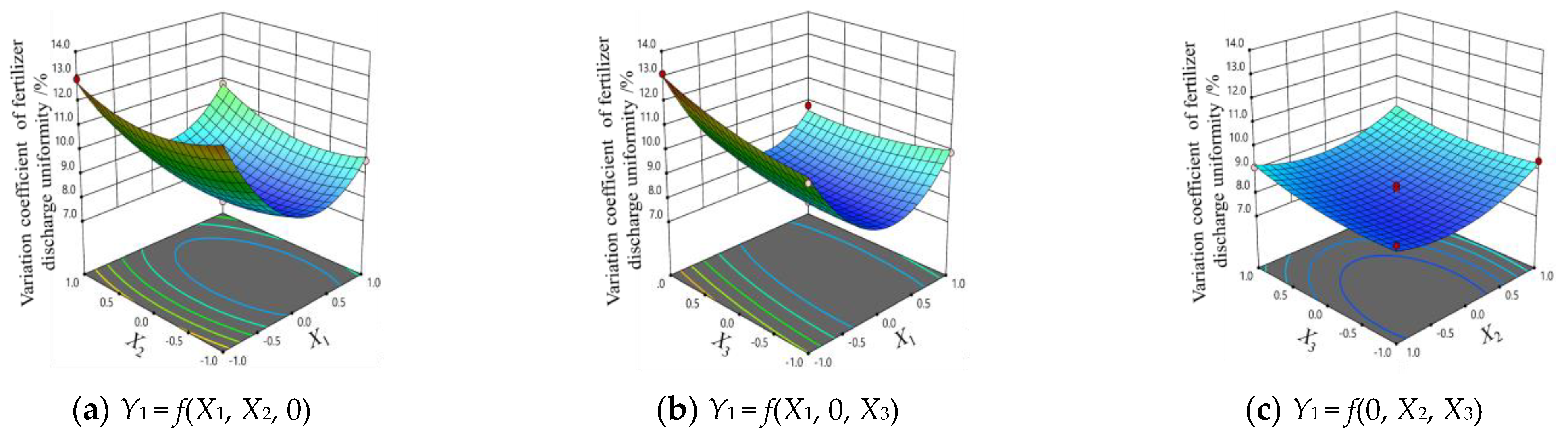
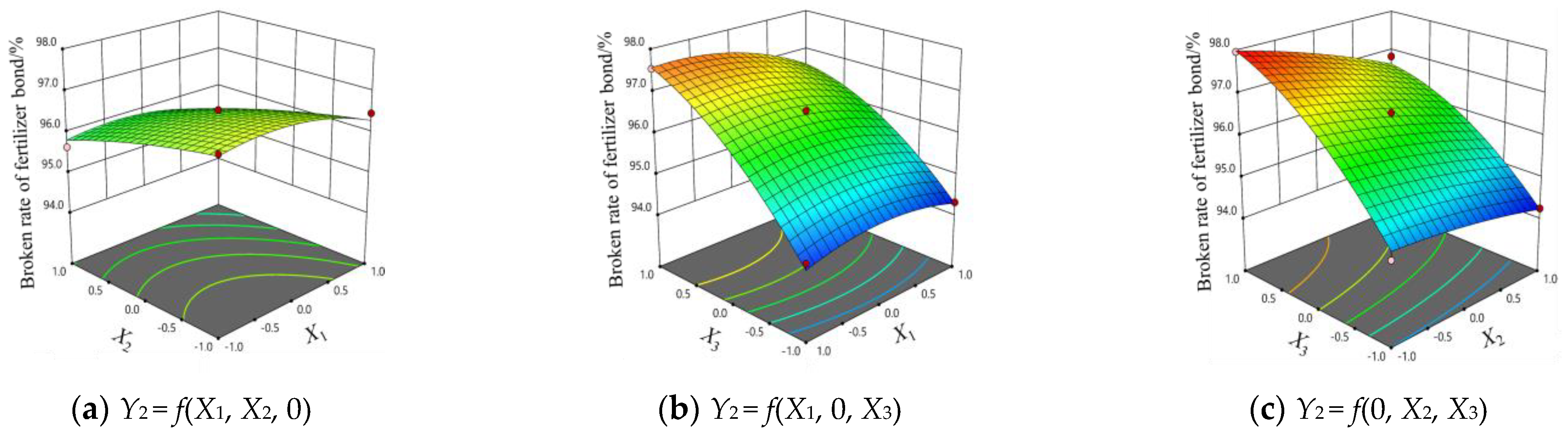
3.2. Analysis of Model Interaction Items

The response surface diagram of the relationship between each factor can be obtained from Equations (10) and (11). The strength of each interaction factor can be judged according to the shape of the response surface. The circle indicates that the interaction between the two factors is not significant, and the ellipse indicates the opposite [30,31].
It can be seen from Figure 10a that when the cross-sectional shape of the GW is a fixed horizontal value, the variation coefficient of fertilizer discharge uniformity tends to decrease first and then increase with the increase in the GW speed. When the GW speed is 21 R/min, the variation coefficient of fertilizer discharge uniformity reaches the minimum value. When the spiral rise angle is a fixed horizontal value (Figure 10b), the variation coefficient of fertilizer discharge uniformity decreases first and then increases with the increase in GW speed, with a significant change range. When the rotating speed of the GW is a fixed level, the variation coefficient of fertilizer discharge uniformity is little affected by the increase in the helix angle. It can be seen from the response surface shape and contour density that the interaction between the cross-sectional shape of the GW and the helix lift angle has no obvious effect on the variation coefficient of fertilizer discharge uniformity, which is the same as the result of variance analysis (Figure 10c). When the section shape of the GW is a fixed horizontal value, the increase in the helix angle has little effect on the variation coefficient of fertilizer discharge uniformity.
In the analysis of the interaction factors on the bond fracture rate, when the section shape of the GW is a fixed horizontal value, with the increase in the GW speed, there is little effect on the broken rate of fertilizer; The interaction between the GW speed and the GW section shape has no significant effect on the broken rate of fertilizer, which is consistent with the variance analysis results (Figure 11a). In Figure 11b, when the spiral rise angle is a fixed horizontal value, the influence of the GW speed on the broken rate of bond is small; When the GW speed is fixed at a certain level, the broken rate of bond shows an increasing trend with the increase in spiral angle, and the change range is obvious. In Figure 11c, when the section shape of the GW is a circular arc and the spiral rise angle is 70°, the broken rate of bond reaches the maximum value; When the cross-sectional shape of the GW is a fixed horizontal value, the broken rate of the bond increases with the increase in the helix angle, and the change range is obvious. This result is consistent with the analysis result of the influence of the spiral groove rising angle on the circumferential velocity change of fertilizer particles.

3.3. Optimization Analysis

According to the above-mentioned experiment results, in order to better improve the fertilizer discharge performance of the SGWFD, under the constraints of various experiment factors, the minimum variation coefficient of fertilizer discharge uniformity and the maximum broken rate of fertilizer block bond are taken as optimization indicators, and a quadratic regression equation between the above performance indicators and various factors is established to optimize the objectives and determine the best working parameters [32,33]. Constraints are as follows:
{ min Y 1 ( X 1 , X 2 , X 3 ) max Y 2 ( X 1 , X 2 , X 3 ) s . t . { 1 X 1 1 1 X 2 1 1 X 3 1
The regression Equations (10) and (11) were optimized and the optimal parameters of the experiment factors were selected. The optimized experiment indexes were obtained as follows, the variation coefficient of the fertilizer discharge uniformity was 8.56%, the broken rate of fertilizer block bond was 97.67%, and the optimal combination of working parameters was as follows, the rotating speed of the GW was 21 R/min, the cross-sectional shape of the GW was scoop shaped, and the spiral rising angle was 70°.

4. Experiment Verification

The optimal working parameter combination obtained by simulation is experimented and verified in the Mechanics Laboratory of Gansu Agricultural University. The experiment equipment is the intelligent fertilizer discharge experimental platform built by the research group, as shown in Figure 12b. The bench is mainly composed of screw GW fertilizer discharger, fertilizer box, GW drive motor, GW speed regulator, TCRT500 tracking sensor, Arduino UNO R3 single chip microcomputer, conveyor belt, PWM governor, conveyor belt, etc. During the working process of the experiment bench, the forward speed of the conveyor belt can be detected using a TCRT500 tracking sensor, and then fed back to the PWM governor to match the speed of the conveyor belt with the speed of the fertilizer discharger. The fertilizer discharger used in the experiment is a spiral GW with scoop shaped section and 70° spiral lift angle processed by 3D printing technology (Figure 12a). The Urea particles used are the same as Section 2.3.1, and the shape is consistent with that used in the bond model parameter verification experiment. To prevent fertilizer particles from bouncing after falling on the conveyor belt, a layer of laundry detergent was applied to the surface of the conveyor belt before the experiment.
Before the experiment, adjust the vertical height between the fertilizer discharge port and the conveyor belt to 30 mm, and operate the starter for 30 s with the overhead stroke. After the conveyor belt and fertilizer discharger work stably, adjust the forward speed of the conveyor belt to 0.75 m/s and the rotation speed of the fertilizer discharger to 21 R/min, add fertilizer blocks into the fertilizer box, and start timing. The bench experiment is conducted for 10 s in total. The conveyor belt is 2 m in length and 0.4 m in width. There are 10 statistical areas with a length of 20 mm. The bench experiment is repeated 3 times, and the statistical results are taken as the average. The variation coefficient of fertilizer discharge uniformity and the broken rate of fertilizer block bond are calculated by referring to Equations (8) and (9), respectively.
Through statistical calculation, the variation coefficient of fertilizer discharge uniformity was 9.23%, and the broken rate of fertilizer block bond was 94.28%. Compared with the optimal simulation results, the relative data errors are 7.3% and 3.6%, respectively. The results show that the fertilizer breaking effect and uniformity of the screw GW fertilizer discharger are better under the best working parameters.

5. Conclusions

At present, the SGWFD is widely used in various commercial fertilizer applications and is an important carrier for variable rate fertilization. This study used a combination of experimental and simulation methods to study the effects of different SGWFD structures and working parameters on the performance of the variation coefficient of fertilizer discharge uniformity and the broken rate of fertilizer bond. The research results can provide a reference for the structural design and parameter optimization of the SGWFD. The specific research conclusions are as follows:
(1)
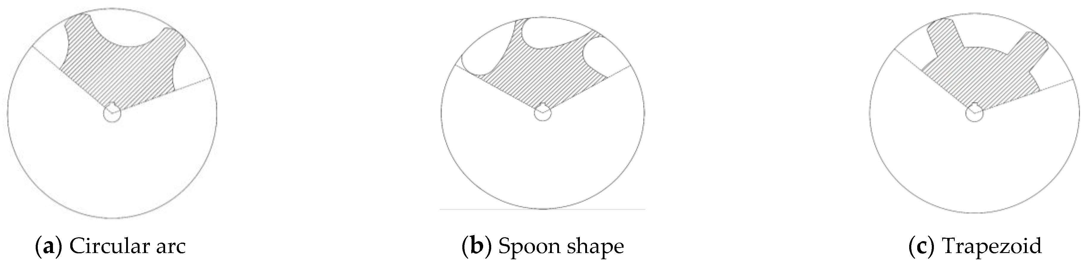
The fertilizer block is constructed based on the bond of the DEM model, and the bond parameters of the fertilizer block are obtained through uniaxial compression experiment and simulation calibration. According to the Box–Behnken experiment design principle, a three-factor three-level response surface simulation experiment was carried out with the GW rotation speed, the GW cross-sectional shape, and the spiral lift angle as factors, and the variation coefficient of fertilizer discharge uniformity and the broken rate of fertilizer block bond as indicators. The quadratic regression model between each factor and the research index was analyzed. Affecting the variation coefficient of fertilizer uniformity, from important to secondary, mainly include the rotating speed of the GW, the sectional shape of the GW and the spiral lift angle. Affecting the broken rate of fertilizer block bond, from important to secondary, mainly include the spiral lift angle, the sectional shape of the GW, and the rotational speed of the GW.
(2)
Taking the minimum variation coefficient of the fertilizer discharge uniformity and the maximum broken rate of the fertilizer block bond as the objectives, the optimal working parameters of the spiral GW were optimized, the GW speed was 21 r/min, the GW section shape was spoon-shaped, and the spiral rise angle was 70°. The variation coefficient of fertilizer discharge uniformity was 8.56%, and the broken rate of fertilizer block bond was 97.67%.
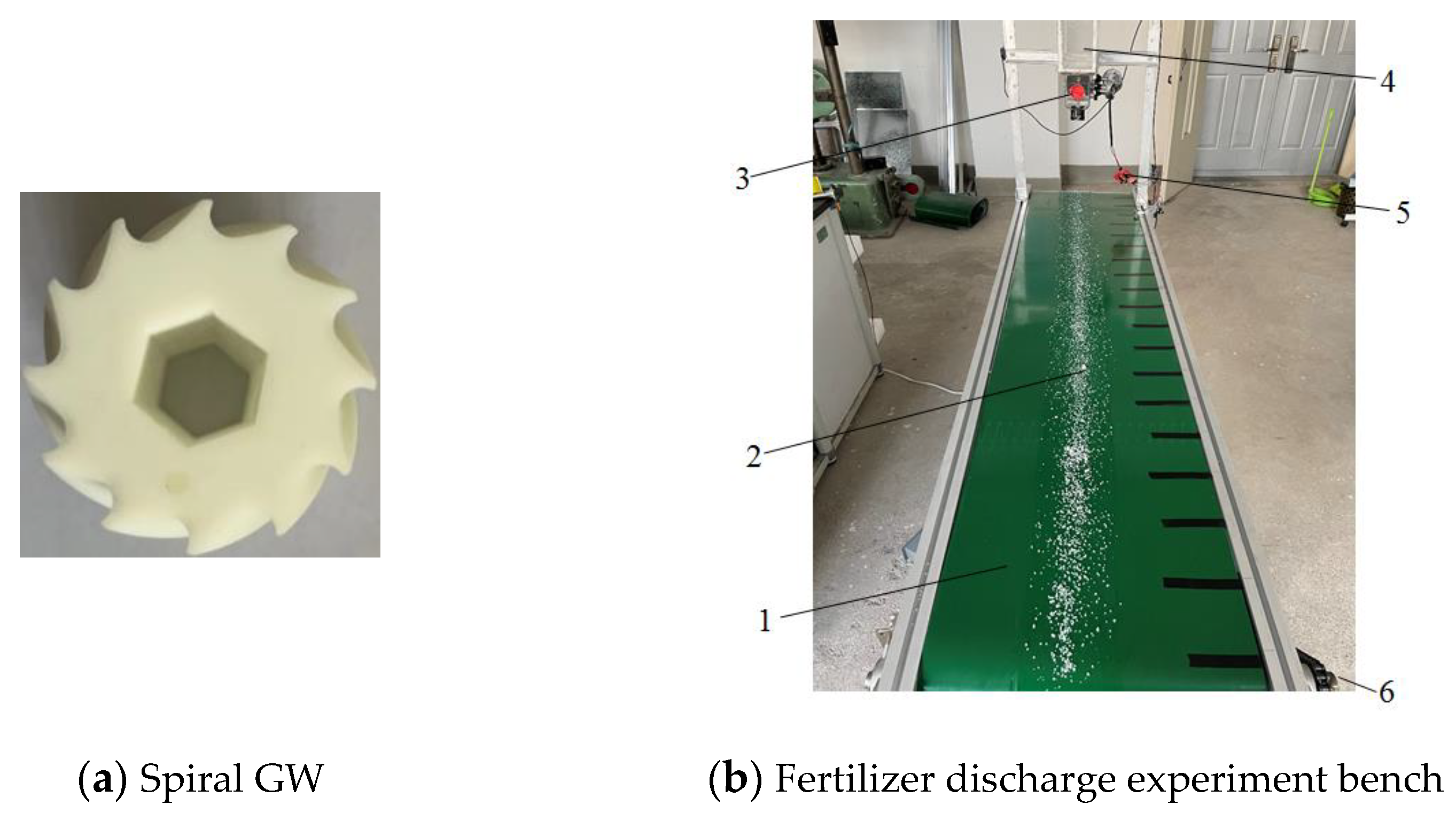
(3)
Build an intelligent fertilizer discharge experiment bench to verify the optimal working parameter combination obtained by simulation. The variation coefficient of fertilizer discharge uniformity was 9.23% and the broken rate of fertilizer block bond was 94.28%. Compared with the simulation results, the relative data errors were 7.3% and 3.6%, respectively, which proves that the experiment data are basically consistent with the simulation data.

Author Contributions

Conceptualization, F.D. and X.Z.; methodology, X.S.; software, X.S.; writing—original draft preparation, X.S.; writing—review and editing, X.S.; experiment, W.G. and X.L.; supervision, F.Z. and W.Z. All authors have read and agreed to the published version of the manuscript.

Funding

The authors would like to thank the reviewers for their hard work. The authors also acknowledge the financial support for this work provided by the University Innovation Fund of Gansu Province (Grant No. 2021B-140), the Outstanding Youth Foundation of Gansu Province (Grant No. 20JR10RA560), Major Science and Technology Projects of Gansu Province (Grant No. 21ZD4NA012), the Natural Science Foundation of China (Grant No. 52065005).

Institutional Review Board Statement

Not applicable.

Informed Consent Statement

Not applicable.

Data Availability Statement

Not applicable.

Conflicts of Interest

The authors declare no conflict of interest.

References

  1. Lei, X.; Li, M.; Zhang, L.; Ren, W. Design and experiment of horizontal pneumatic screw combination adjustable quantitative fertilizer feeding device for granular fertilizer. Trans. Chin. Soc. Agric. Eng. 2018, 34, 9–18. [Google Scholar]
  2. Zhang, L.; Zhang, L.; Zheng, W. Fertilizer feeding mechanism and experimental study of a spiral grooved-wheel fertilizer feeder. J. Eng. Sci. Tech. Rev. 2018, 11, 107–115. [Google Scholar]
  3. National Bureau of Statistics of China. China Statistical Yearbook 2021; China Statistics Press: Beijing, China, 2021.
  4. Liu, X.; Ding, Y.; Shu, C.; Wang, K.; Liu, W.; Wang, X. Mechanism analysis and experiment of disturbance and blockage prevention of spiral cone centrifugal fertilizer apparatus. Trans. Chin. Soc. Agric. Mach. 2020, 51, 44–54. [Google Scholar]
  5. Wang, H.; Chen, H.; Ji, W. Anti-blocking mechanism of type 2BMFJ-3 No-till precision planter for wheat stubble fields. Trans. Chin. Soc. Agric. Mach. 2013, 44, 64–70. [Google Scholar]
  6. Tola, E.; Kataoka, T.; Burce, M.; Okamoto, H.; Hata, S. Granular fertilizer application rate control system with integrated output volume measurement. Biosyst. Eng. 2008, 101, 411–416. [Google Scholar] [CrossRef]
  7. Dun, G.; Chen, H.; Feng, Y.; Yang, J.; Li, A.; Cha, S. Parameter optimization and experiment of key parts of fertilizer allocation device based on EDEM software. Trans. Chin. Soc. Agric. Eng. 2016, 32, 36–42. [Google Scholar]
  8. Song, C.; Zhou, Z.; Wang, G.; Wang, X.; Zang, Y. Optimization of the groove wheel structural parameters of UAV-based fertilizer apparatus. Trans. Chin. Soc. Agric. Eng. 2021, 37, 1–10. [Google Scholar]
  9. Sugirbay, A.M.; Zhao, J.; Nukeshev, S.O.; Chen, J. Determination of pin—Roller parameters and evaluation of the uniformity of granular fertilizer application metering devices in precision farming. Comput. Electron. Agric. 2020, 179, 105835. [Google Scholar] [CrossRef]
  10. Zhang, J.; Liu, G.; Hu, H.; Huang, J.; Liu, Y. Influence of control sequence of spiral fluted roller fertilizer distributer on fertilization performance. Trans. Chin. Soc. Agric. Mach. 2020, 51 (Suppl. S1), 137–144. [Google Scholar]
  11. Lv, H.; Yu, J.; Fu, H. Simulation of the operation of a fertilizer spreader based on an outer groove wheel using a discrete element method. Math. Comput. Model. 2013, 58, 842–851. [Google Scholar] [CrossRef]
  12. Zeng, S.; Tan, Y.; Wang, Y.; Luo, X.; Yao, L.; Huang, D.; Mo, Z. Structural design and parameter determination for fluted-roller fertilizer applicator. Int. J. Agric. Biol. Eng. 2020, 13, 101–110. [Google Scholar] [CrossRef]
  13. Sun, J.; Chen, H.; Duan, J.; Liu, Z.; Zhu, Q. Mechanical properties of the grooved-wheel drilling particles under multivariate interaction influenced based on 3D printing and EDEM simulation. Comput. Electron. Agric. 2020, 172, 105329. [Google Scholar] [CrossRef]
  14. Cundall, P.A.; Strack, O.D.L. A discrete numerical model for granular assemblies. Geotechnique 1979, 29, 47–65. [Google Scholar] [CrossRef]
  15. Rackl, M.; Hanley, K.J. A methodical calibration procedure for discrete element models. Powder Technol. 2017, 307, 73–83. [Google Scholar] [CrossRef] [Green Version]
  16. Potyondy, D.O.; Cundall, P.A. A bonded-particle model for rock. Int. J. Rock Mech. Min. Sci. 2004, 41, 1329–1364. [Google Scholar] [CrossRef]
  17. Cho, N.; Martin, C.D.; Sego, D.C. A clumped particle model for rock. Int. J. Rock Mech. Min. Sci. 2007, 44, 997–1010. [Google Scholar] [CrossRef]
  18. Yan, Z.; Wilkinson, S.K.; Stitt, E.H.; Marigo, M. Discrete element modelling (DEM) input parameters: Understanding their impact on model predictions using statistical analysis. Comput. Part. Mech. 2015, 2, 283–299. [Google Scholar] [CrossRef] [Green Version]
  19. Yuan, J.; Liu, Q.; Liu, X.; Zhang, T.; Zhang, X. Simulation of multi-fertilizers blending process and optimization of blending cavity structure in nutrient proportion of variable rate fertilization. Trans. Chin. Soc. Agric. Mach. 2014, 45, 125–132. [Google Scholar]
  20. Quist, J. Cone Crusher Modelling and Simulation; Chalmers University of Technology: Gothenburg, Sweden, 2012. [Google Scholar]
  21. Xu, J.; Xie, Z.; Jia, H. Simulation of mesomechanical properties of limestone using particle flow code. Rock Soil Mech. 2010, 31, 390–395. [Google Scholar]
  22. ASAE S368.4 DEC2000 (R2008); Compression Experiment of Food Materials of Convex Shape. American Society of Agricultural and Biological Engineers: St. Joseph, MO, USA, 2008.
  23. Zhu, Q.; Wu, G.; Chen, L.; Zhao, C.; Meng, Z. Influences of structure parameters of straight flute wheel on fertilizing performance of fertilizer apparatus. Trans. Chin. Soc. Agric. Eng. 2018, 34, 12–20. [Google Scholar]
  24. Zheng, K.; He, J.; Li, H.; Dao, P.; Wang, Q.; Zhao, H. Research on polyline soil-breaking blade subsoiler based on subsoiling soil model using discrete element method. Trans. Chin. Soc. Agric. Mach. 2016, 47, 62–72. [Google Scholar]
  25. NY/T1003—2006; Technical Specification for Quality Price of Fertilizer Machinery. China Standards Press: Beijing, China, 2015.
  26. Liu, J.; Tang, Z.; Zheng, X.; Meng, X.; Yang, H.; Zhang, L. Design and experiments of the 2FHF-4.56 type base-fertilizer row-following and layered deep fertilizing machine for wide row spacing crops. Trans. Chin. Soc. Agric. Eng. 2022, 38, 1–11. [Google Scholar]
  27. Zhu, H.; Qian, C.; Bai, L.; Li, H.; Mou, D.; Li, J. Optimization of discrete element model of corn stalk based on Plackett-Burman design and response surface methodology. J. China Agric. Univ. 2021, 26, 221–231. [Google Scholar]
  28. Dai, F.; Zhao, W.; Song, X.; Shi, R.; Liu, G.; Wei, B. Parameters optimization and experiment on separating and cleaning machine for flax threshing material. Trans. Chin. Soc. Agric. Mach. 2020, 51, 100–108. [Google Scholar]
  29. Du, X.; Liu, C.; Jiang, M.; Yuan, H.; Dai, L.; Li, F. Calibration of bonding model parameters for coated fertilizers based on discrete element method. Trans. Chin. Soc. Agric. Mach. 2022, 53, 141–149. [Google Scholar]
  30. Yi, J.; Zhu, W.; Ma, H.; Wang, Y. Optimization on ultrasonic-assisted extraction technology of oil from Paeonia suffruticosa Andr. seeds with response surface analysis. Trans. Chin. Soc. Agric. Mach. 2009, 40, 103–110. [Google Scholar]
  31. Yuan, X.; Qi, L.; Wang, H.; Huang, S.; Ji, R.; Zhang, J. Spraying parameters optimization of swing, automatic variables and greenhouse mist sprayer with response surface method. Trans. Chin. Soc. Agric. Mach. 2012, 43, 45–54. [Google Scholar]
  32. Liu, L.; Ma, C.; Liu, Z. EDEM-based parameter optimization and experiment of full-layer fertilization shovel for strip subsoiling. Trans. Chin. Soc. Agric. Mach. 2021, 52, 74–83. [Google Scholar]
  33. Wang, X.; Zhang, Q.; Huang, Y.; Ji, J. An efficient method for determining DEM parameters of a loose cohesive soil modelled using hysteretic spring and linear cohesion contact models. Biosyst. Eng. 2022, 215, 283–294. [Google Scholar] [CrossRef]
Figure 1. Schematic diagram of bond model. Note: Fi,b is the resultant of forces of particle A acting on particle B; M b n , M b s , are normal torque and tangential torque, respectively; ni, τi are normal and tangential components, respectively; L b is the overlap of particle A and particle B; Rb is the bond radius.
Sustainability 15 11309 g001
Figure 2. Structural diagram of spiral GW fertilizer apparatus. 1. Stiff brush; 2. Spiral GW; 3. Fertilizer box; 4. Fertilizer tongue.
Sustainability 15 11309 g002
Figure 3. Fertilizer particle measurement process and equivalent diameter distribution.
Sustainability 15 11309 g003
Figure 4. Filling process of fertilizer block model.
Sustainability 15 11309 g004
Figure 5. Fertilizer block material and bond model.
Sustainability 15 11309 g005
Figure 6. Uniaxial compressive force–time relationship of fertilizer block.
Sustainability 15 11309 g006
Figure 7. Working process simulation of fertilizer apparatus. 1. Ground; 2. Fertilizer particles; 3. Statistical areas; 4. Fertilizer block; 5. Spiral GW.
Sustainability 15 11309 g007
Figure 8. Spiral GW section shape.
Sustainability 15 11309 g008
Figure 9. Broken simulation process of fertilizer blocks.
Sustainability 15 11309 g009
Figure 10. Effects of part interactive factors on variation coefficient of fertilizer discharge uniformity.
Sustainability 15 11309 g010
Figure 11. Effect of part interactive factors on broken rate of fertilizer bond.
Sustainability 15 11309 g011
Figure 12. Bench experiment verification. 1. Conveyor belt; 2. Fertilizer; 3. SGWFD; 4. Fertilizer box; 5. Motor speed regulator of spiral GW; 6. Power motor of conveyor belt.
Sustainability 15 11309 g012
Table 1. Bond parameters of fertilizer block.
ParametersValue
Normal stiffness per unit area (N/m3)3 × 109
Shear stiffness per unit area (N/m3)2 × 108
Critical normal stress/Pa1 × 105
Critical shear stress/Pa8 × 104
Bonded disk radius/mm2.5
Table 2. Material contact parameters.
Contact ParametersFertilizer-FertilizerFertilizer-PLAFertilizer-Ground
Coefficient of restitution0.110.410.02
Coefficient of static friction0.370.321.25
Coefficient of rolling friction0.160.181.24
Table 3. Coding of factors.
CodingFactor
X1/(r/min)
GW Speed
X2
GW Section Shape
X3/(°)
Spiral Angle
−115Circular arc60°
020Spoon shape65°
125Trapezoid70°
Table 4. Statistical table of response surface simulation experiment data.
NumberX1X2X3Y1/%Y2/%
11−109.5796.47
2−10−111.1494.48
3−1−1012.5196.82
40119.4596.84
5−10113.1197.54
60008.3496.26
70008.0496.55
8−11012.9095.64
910−19.9294.31
1011010.7995.26
1101−19.3994.24
120008.1096.39
130007.8696.55
141019.896.46
150008.1896.55
160−119.1297.96
170−1−18.5894.64
Table 5. Variance analysis of regression equation.
Experiment IndexSources of VarianceSum of SquaresDfMean SquareFp-Value
Variation coefficient of fertilizer discharge uniformityModel47.1295.2495.97<0.0001 **
X111.47111.47210.31<0.0001 **
X20.9510.9517.330.0042 **
X30.7510.7513.750.0076 **
X1X20.1710.173.160.1188
X1X31.9711.0920.020.0029 **
X2X30.0610.061.060.3383
X1228.42128.42520.99<0.0001 **
X222.3112.3142.330.0003 **
X320.3610.366.510.0380 *
Residual0.3870.06
Lack of fit0.2630.092.740.1778
Pure error0.1340.03
Sum total47.5016
Broken rate of fertilizer bondModel19.6392.1858.57<0.0001 **
X10.4910.4913.160.0084 **
X21.9111.9151.330.0002 **
X315.48115.48415.89<0.0001 **
X1X20.00022510.0002250.0060430.9402
X1X30.2110.215.560.0505
X2X30.1310.133.480.1043
X120.4210.4211.400.0118 *
X220.0410.041.020.3460
X320.8310.8322.390.0021 **
Residual0.2670.04
Lack of fit0.1930.063.690.1198
Pure error0.0740.02
Sum total19.8916
Note: ** shows significant effect (p ≤ 0.01). * shows notable effect (p ≤ 0.05).
Disclaimer/Publisher’s Note: The statements, opinions and data contained in all publications are solely those of the individual author(s) and contributor(s) and not of MDPI and/or the editor(s). MDPI and/or the editor(s) disclaim responsibility for any injury to people or property resulting from any ideas, methods, instructions or products referred to in the content.

