1. Introduction
Over the centuries, the climate has been the factor that has most influenced the thermo-hygrometric conditions of religious buildings [
1], that more often than not are without performing systems and sometimes they totally lack them too.
The indiscriminate use of systems often became a critical element for the conservation and protection of architectural values and quality [
2]. The liturgical environments of churches are usually characterized by large volumes and massive construction systems with high thermal inertia, which, while ensure moderate thermal comfort in summer, produce very critical conditions in winter.
With the spread of themes related to the need to contain energy consumption and improve comfort conditions, religious buildings have also become objects of interest for the international scientific community in relation to these research areas. This is happened above all in the countries where there is a large number of this kind of building and therefore, they impact on the achievement of the sustainable development goals (SDGs) of the 2030 Agenda. For instance, this can be seen in Italy, which owns 4.7% of the world’s architectural heritage and where this one represents 46% of the entire country, or also in many other countries of the Mediterranean area [
3].
In recent years, the theme of environmental comfort of cultural heritage has been strongly associated with the need to improve the energy performance of buildings, in relation to the reduction of energy consumption for heating and cooling. Nonetheless, it should be considered that efficient heating systems are not always able to guarantee user comfort and energy savings at the same time: in fact, the way in which the space is used is the determining variable to be controlled and managed for this purpose, especially considering the changes in the intended use that historical architectures undergo over time. Other than that, there are still many aspects to consider and critical issues to solve. Among the main ones, it is possible to include the problems concerning the maintenance of the indoor microclimate for conservation goals, the lack of knowledge of the properties of the building envelope elements—often characterized by anisotropic construction elements [
4] reworked over the years, the absence of specific software for the design and management of the built heritage, that are dedicated almost exclusively to new buildings [
5]. Therefore, the theme is particularly felt in the international scientific community with a growth in the interest of researchers in recent years. Ref. [
6] study how to improve the energy performance of one of the partitions of a historical church aiming to reduce the degradation of the construction element and, at the same time, to maintain the appropriate indoor microclimate for conservation goals. Ref. [
7] analyze heating strategies for the “Basilica di S. Maria di Collemaggio”, verifying as traditional heating strategies are compared with solutions for the local-comfort, such as the pew-based heating, and a novel hydronic high-efficiency pew-based system, that was proposed and deeply analyzed. Ref. [
8] identify the strategies to improve the energy performance of a historical building in Zakopane (Poland) by carrying out non-invasive analysis, identifying the critical elements and introducing a layer of thermal insulation on the envelope internal side. Ref. [
9] verify the application of selective passive strategies in two ecclesiastical buildings, since they consider it necessary to give priority to these systems over those of mechanical air conditioning for the achievement of a sustainable and comfortable indoor environment.
A hot topic that is affecting the scientific community is the religious buildings monitoring, especially from the point of view of the indoor microclimate. This choice stems from the fact that monitoring data are often used to better calibrate simulation models. In this way, technological systems can be ‘tested’ virtually, reducing the risks associated with their application in valuable contexts [
10].
Monitoring is also employed to control religious buildings under different potential impact conditions, including, for example, biotic damage [
11], comfort conditions related to internal ventilation [
12,
13], and changes in humidity parameters as a function of the user [
14].
The issue of the risks associated with the introduction of heating systems is strongly emphasized, since these environments are created without such elements. In particular, ref. [
15] monitor the impact of overhead radiant heaters on air flows, the microclimate in general and the deposition of suspended particles in the presence of artwork. They show how, with proper care, such systems are able to provide localized heat, without creating negative impacts on the artwork. Finally, ref. [
16] verified how in the UK, where in most churches a heating system has been installed, damage has been experienced due to fluctuating conditions related to intermittent occupancy. These conditions, according to the authors, must be strongly considered when defining intervention strategies.
As argued, it is evident that the research concerning the improvement of comfort conditions in liturgical spaces is not concluded, because there are many gaps to be filled, in-depth studies to be carried out and results to be achieved.
This paper is aimed at contributing to overcome the critical issues identified through the development of a methodology intended to optimize the management of environmental comfort and the energy consumption of churches following restoration, reuse and re-functionalization interventions, using appropriate monitoring techniques.
2. Modalities of Fruition in Historical Buildings: Impact on Comfort and Energy Issues
In the past, the main “regulating diaphragm” of the comfort of the historical buildings was the envelope: thanks to the peculiar property represented by the modulation of the heat exchange between the indoor and outdoor environment, the massive stone walls contributed in a dominant way to the definition of the indoor microclimate of the buildings, as these are predominantly devoid of thermal systems for heating [
17].
The performance and system adaptation, often unscrupulous, which affected the cultural heritage in the last decades of the 20th century did not invest with the same speed and voracity the artefacts with “discontinuous use” such as religious buildings, for reasons mainly related to the low efficiency of thermal plants in relation to the important volumes and, therefore, to the effective convenience in terms of costs and benefits of the investments. Due to this process, the microclimate in the liturgical spaces may generally be considered little altered compared to the original and this has allowed an easier conservation of the included valuable works [
18].
Over the last decades, also thanks to the attention paid to the monitoring of the state of conservation of historical artefacts in relation to changes in the use of environments, it has been possible to experiment with the application of contemporary heating systems—for instance, the radiant floor panels, already widely used for the air-conditioning of houses and offices—even in worship places. They had a moderate success in terms of impact on the conservation of historical and artistic values, considering the low operating temperatures of the heat transfer fluids used [
19]. On the other hand, in buildings that have not undergone recent restorations and renovations, in order to counteract discomfort, there is a widespread use of electric splits or infrared lamps which, while guaranteeing extreme flexibility, reversibility, low cost of installation and management and an immediate regime, have many side-effects related to the questionable aesthetic impact, the release of gas into the environment, the risk of fire and damage to the surfaces affected by the heat source [
20,
21].
The energy behavior of a building is strongly linked to the functioning of its envelope, which represents a potentially dynamic element, that is able to integrate multiple aspects related to the environmental performance: thermal, hygrometric, luminous, hygienic, etc. Representing the boundary between the outdoor and indoor environments, the building envelope performs, among other things, the important function of guaranteeing the quality of living: it governs the energy flows in the different seasons, controls the thermo-hygrometric exchanges, guarantees the ventilation and natural lighting, reduces the transmission of noise in the internal spaces. So, it is essential to know its features and original performance, in order to set up a correct performance efficiency process [
22]. For this reason, in order to develop a compatible energy renovation project, it would be advisable to combine the analysis of the performance of the systems with the one of the envelope behavior, in order to combine interventions aimed at both reducing consumption and improving the thermo-hygrometric properties of masonry, openings and roofing.
3. Methods and Tools
In this work the phases of the performance optimization project involve the analysis of the state-of-the-art and, in particular, an in-depth comfort diagnosis carried out by means of a monitoring campaign developed with non-destructive analysis methods, such as the thermographic technique [
23,
24,
25,
26,
27], the heat-flow measurement [
28,
29,
30,
31] and the indoor microclimate on site monitoring. They are all non-invasive techniques: the first one allows the qualitative analysis of the critical issues, the second one enables the quantitative analysis of the thermal performance of the envelope through the identification of the real thermal transmittance values of the building elements and the third one allows to promptly understand the comfort condition of the environment in relation to the activity of the user. On the basis of the data obtained, the main performance criticalities of the building related to comfort conditions were identified.
The research process may be summarized in the following steps:
Step 1. Analysis of archival sources and in-situ investigations; comfort diagnosis of the actual fruition mode of the structure aimed at an in-depth knowledge of the existing building features.
Step 2. Construction of the model for the dynamic simulations on the basis of the data acquired in the previous step.
Step 3. Quantification of the indoor comfort of the retrofit solution through dynamic simulation of the model validated in the Step 2.
In the case-study of the S. Vito church in L’Aquila, following the previous steps, it was possible to establish the construction and performance characteristics of the envelope in terms of thermal transmittance, to model the building within a dynamic simulation software basing the model on data acquired from in-situ investigations and, finally, to compare the comfort monitoring data with those of the simulation for different conditions of use of the church, highlighting the criticalities both for the heating systems envisaged by the retrofit (underfloor heating) and for those currently used in the building (infrared lamps).
Case-Study: The San Vito Church, L’Aquila, Italy
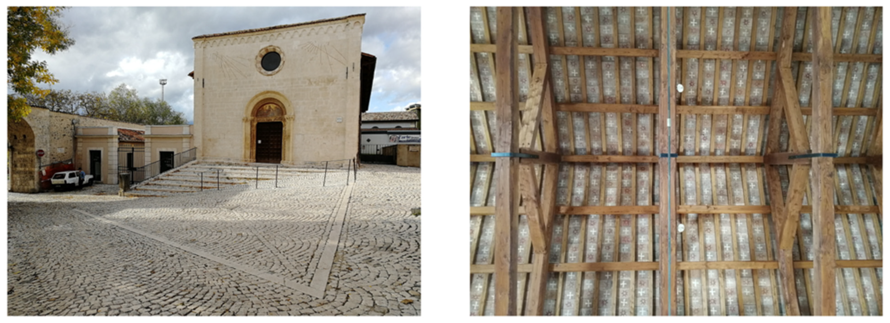
The San Vito church (
Figure 1), characterized by a rectangular plan with a single hall, was built in the second half of the XIII century in the picturesque “Borgo Rivera”—in front of “99 Cannelle” Fountain. The medieval village is part of the “Quarto di S. Giovanni” and the town of L’Aquila sees its foundation here, datable around the second half of the 1200s. The construction of the small church, by Corrado IV of Swabia, a few years after its construction suffered serious damage due to the earthquake that struck the city in 1259. The first reconstruction of the building took place in the 15th century, maintaining the single hall structure, the single portal, the central oculus and the crowning frame on the facade. Then, it was annexed to the Collegiate church of S. Marciano; after the subsequent transfer to the Bonfatelli friars, a convent and a hospital for the sick were founded, both built adjacent to its south-west elevation [
32,
33,
34,
35,
36].
The 1703 earthquake destroyed part of the structure and during the reconstruction the part used as a convent was transformed into a slaughterhouse—currently the seat of the National Museum of Abruzzo. A few years later the church was abandoned as a religious seat; only in 1858 Monsignor Luigi Filippi brought-back the parish of San Vito.
The elevation of the tympanum and the construction, at the end of the nave, of a partition wall between the church and the sacristy, which was thereafter transformed in a vicarage [
37,
38], date back to the first half of the 20th century. The 2009 earthquake compromised the masonry structure again, causing the collapse of part of the main facade, in addition to widespread damage to the masonry walls. Following the restoration work carried out in the years between 2014 and 2017, the church is now in an excellent state of conservation, the deterioration of the walls is limited to phenomena of exfoliation and efflorescence, while the damage to the structures is absent. The pavilion roof has wooden trusses with secondary and tertiary warping of purlins and stringers to support decorated terracotta tiles. These tiles, with the exception of the external elevations enriched by the sculptural portal with frescoed lunette and the stone intrados of the windows, stand out as a valuable element in the essential spatiality of the hall, characterized by the absence of a decorative apparatus. The historical information reported in this paragraph derives from an archival research carried out at the State Archive of L’Aquila and from the Archdiocesan Archive of L’Aquila.
4. Analysis and Diagnosis of the Current State
The proposed methodology is applied to the case-study with the aim of optimizing the microclimate and comfort management of the church through the hypothesis of the application of minimally invasive interventions on the building envelope and the integration of plant technologies characterized by low energy demand and reduced environmental impact. The design strategies were determined in compliance with the energy efficiency project, already applied in the restoration phase which, as may be seen from the environmental diagnosis of the current state, contributed to an improvement in the performance of the entire architectural complex [
39].
Through the state-of-the-art analysis, a singular management of the heating systems was found in the church of S. Vito: the hall is in fact currently equipped with the new and functioning underfloor heating system applied following the recent renovation works and infrared lamps. The latter are the only ones actually used to improve winter comfort in the hall. In fact, the use discontinuity of the church—which remains unused for long periods of the year and, when in use, it is mainly exploited to host celebrations on a weekly basis—does not allow the radiant panels to operate efficiently, causing user discomfort and an excessive economic expenditure for the property.
4.1. Non-Destructive Analysis of the Building Envelope of the San Vito Church: The Thermographic and Heat-Flow Measurement Campaign
When it happens to intervene on historical buildings, there is a known lack of data related to the knowledge of pre-intervention hygrothermal performance, as well as a series of constraints that make it difficult to identify compliant strategies [
40,
41]. A particular attention in safeguarding the original characteristics of the envelope is required for interventions on historical masonry, especially in the case of listed churches.
In the case of the San Vito church, the performance of the vertical closures, mainly characterized by very thick limestone ashlars (70–80 cm), were investigated through a heat flow measurement campaign (the instrument used is the TESTO 434.2 that includes a datalogger, radio probes for measuring surface and external air temperatures, a heat flow meter plate in order to measure the heat flow), consisting of non-destructive measurements regulated by the ISO 9869-1:2014 standard [
31], which sets very strict test conditions in order to have reliable results [
42] regarding the energy behavior of historical masonry and their transmittance values [
43,
44,
45].
Before proceeding with the measurement, a thermographic investigation on all facades was conducted, with the exception of the south-west elevation where it was not possible to access, due to external works on the adjacent property. Thermographic analysis was carried out to identify homogeneous portion of masonry suitable for carrying out measurements with the thermo-flowmeter. In fact, this type of analysis allows to evaluate structural discontinuities in the masonry (often caused by remaking of the structure over time with different materials) which would distort the real value of the transmittance of the envelope. An example is shown in
Figure 2: the south-east façade was analyzed both in the first heating phase (left image) and second heating phase (right image). The two images (processed with the FLIR TOOL+ 6.4 software, which allowed the thermal calibration of the color and temperature scales), taken when the masonry was in active heating mode, confirm the structural discontinuities on the elevation (please refer the gray rectangles in the
Figure 2) probably due to subsequent renovations; in the case of the top band of the facade, the portion of masonry is at a lower temperature also because it is not protected from the rear by the roof, which is located at a lower level. In accordance with standard, the measurement lasted for more than 72 h. Once the data were extrapolated, their verification and analysis were performed through the application of the progressive average method, in order to obtain the transmittance value of the investigated masonry (
Figure 3), that resulted 1.766 W/m
2K. This value was then used in the next analysis with Design Builder software (7.0.0.116 version) together with the roof transmittance value obtained by reconstructing the stratigraphy of the roof and then estimated at value 2.941 W/m
2K (this value was confirmed in the Design Builder model).
4.2. The Indoor Comfort Monitoring
The discomfort condition has been checked on site by a comfort diagnosis carried out with the usage of the TESTO 400 comfort kit [
46]. In order to carry out the monitoring in the correct way, some parameters have been set as input for the instrument: these are the metabolic rate (MET) and the clothing level (CLO). The monitoring of comfort conditions in the church also allows us to acquire thermohygrometric data from the environment under different usage condition as output of the process. The instrument automatically processes the outputs providing the Fanger comfort indexes: the Predicted Mean Vote (PMV) and the Predicted Percentage of Dissatisfied (PPD) [
47,
48].
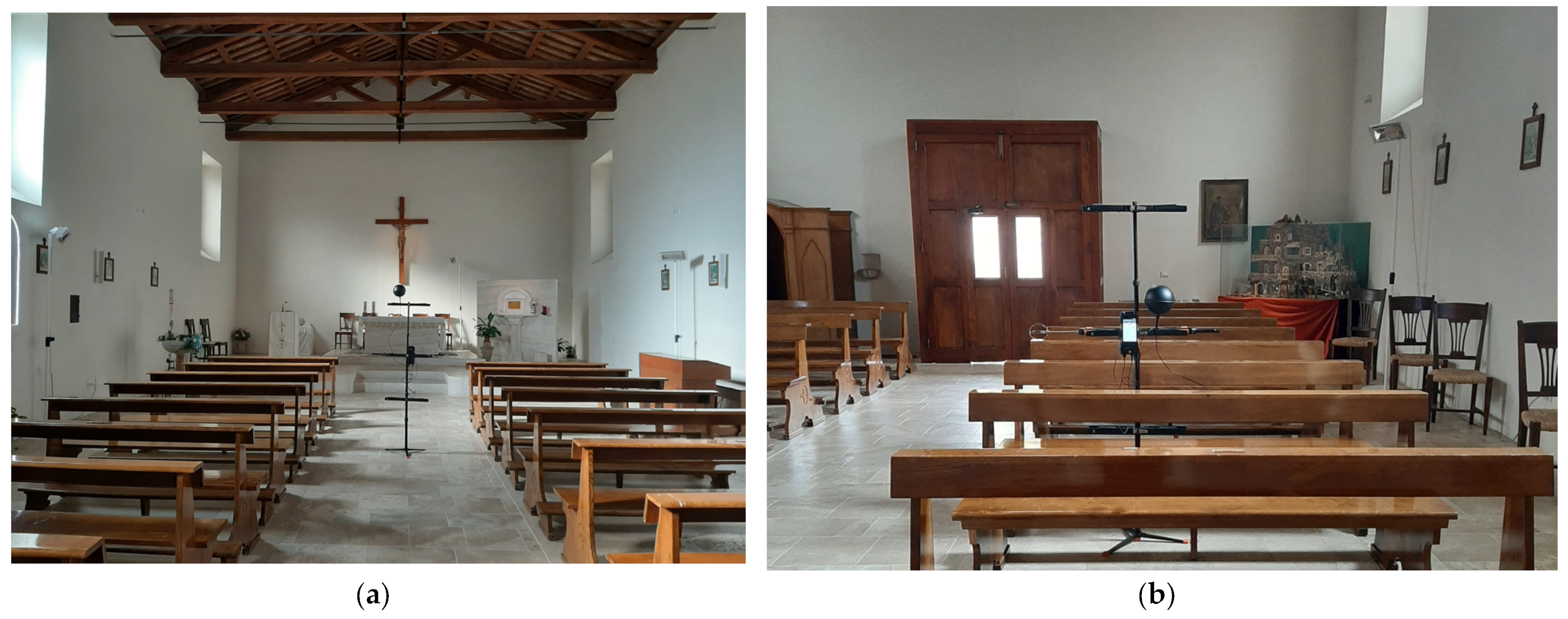
The internal comfort measurements were taken under 2 different conditions and after the conclusion of a religious ceremony with the full church: (i) lamps off and user standing in the center of the room; (ii) lamps off and user seated (
Figure 4).
The input and output data for each of the conditions described are shown in the following table (
Table 1) and refers to the monitoring data from the TESTO instrument. For greater results reliability, Fanger comfort indices (PPD and PMV) have been reworked by the authors using the Center for the Built Environment (CBE) thermal comfort tool for thermal comfort calculations and visualizations [
49] that complies with the ASHRAE 55–2017 [
50], ISO 7730:2005 [
48] and EN 16798–1:2019 [
51] Standards.
It should be noted that in this starting phase the monitoring was carried out when the church was empty and with the infrared lamps off. The first monitoring (Case i) was carried out on 20 November 2022—when the dry bulb outdoor temperature was around 5 degrees at 13.00 p.m.—from 1:15 p.m. to 1.30 p.m.; the second monitoring (case ii) was carried out from 1:30 p.m. to 1:45 p.m. on the same day. This fact explains the slight decrease in temperature between Case i and Case ii as well as the variation of the relative humidity value (RH%): during the monitoring time the people had left the hall of the church and the infrared lamps had been turned off for about 30 min before the data acquisition.
Anyway, these slight fluctuations have little impact on the PMV and PPD indices, for which the inputs MET and CLO are instead decisive. From the monitoring results presented in
Table 1, it can be seen that in the 2 cases analyzed, the users are in a quite different comfort condition. As expected, the Case i, thanks to the MET value related to the standing activity, allow to keep users in the comfort zone of the psychrometric chart, as shown in
Figure 5. Case ii shows a different comfort situation: when the people are seated and relaxed—and this represents the typical condition for most users during religious celebrations—they are in discomfort conditions (
Figure 6).
4.3. Modelling and Dynamic Simulation
After the cognitive analysis (step 1), a model for dynamic energy simulations was created on Design Builder software.
The methodological process followed in this work aims to assess the indoor comfort obtainable inside the room thanks to the use of radiant floor panels installed in the church after the renovation. These types of heating have the advantage of a low impact on the microclimate, of avoiding vertical temperature stratification and of guaranteeing individual heating, however with limited thermal power. For this reason, it was necessary to verify the efficiency of the new plant system using the energy simulation software, EnergyPlus, through the Design Builder graphic interface. In order to ensure a correct construction of the simulation model, the monitoring campaign data with a heat-flow meter were used, which allowed to insert within the calculation model the effective transmittance value 1.766 W/m
2K of the masonry of the case-study (
Figure 4).
Once the model was built, in order to verify its reliability, a first simulation was carried out with the heating off, with the purpose of comparing the thermo-hygrometric parameters and the internal comfort results from the simulation with the ones measured in situ during the monitoring campaign and reported in
Table 1 and in the
Figure 5 and
Figure 6.
The results of the “model verification simulation” are shown in the following
Table 2 and in
Figure 7 and
Figure 8. As in the monitoring campaign, the internal comfort measurements were simulated under two different conditions: (i) heating off and users standing/walking in the center of the room; (ii) heating off and users seated.
The data shown in
Table 2 correspond to the psychrometric parameters resulting from the dynamic simulation for a typical winter day. The results obtained in terms of comfort, air temperature and relative humidity in the hall confirm the reliability of the simulation model defined: the slight deviation of the values obtained with respect to the monitoring values is admissible and justified by the fact that the monitoring data have been slightly altered by the celebration that took place in the hall of the church (presence of about 70 people and lamps on) up to about 30 min before the data acquisition with the usage of the TESTO 400 comfort kit.
Therefore, the results confirm the particular state of discomfort of the users when they are in case ii (sitting in church, relaxed, with no functioning heating system). The discomfort is significantly reduced if the users attend the celebration standing up (case i). At this point, having validated the correct functioning of the simulation model, it was possible to insert the input data related to the retrofit intervention applied to the church into the construction templates of the model, in order to evaluate the benefits in terms of comfort improvement.
5. Results and Discussion
After having calibrated and validated the model for the dynamic simulations thanks to in situ monitoring data [
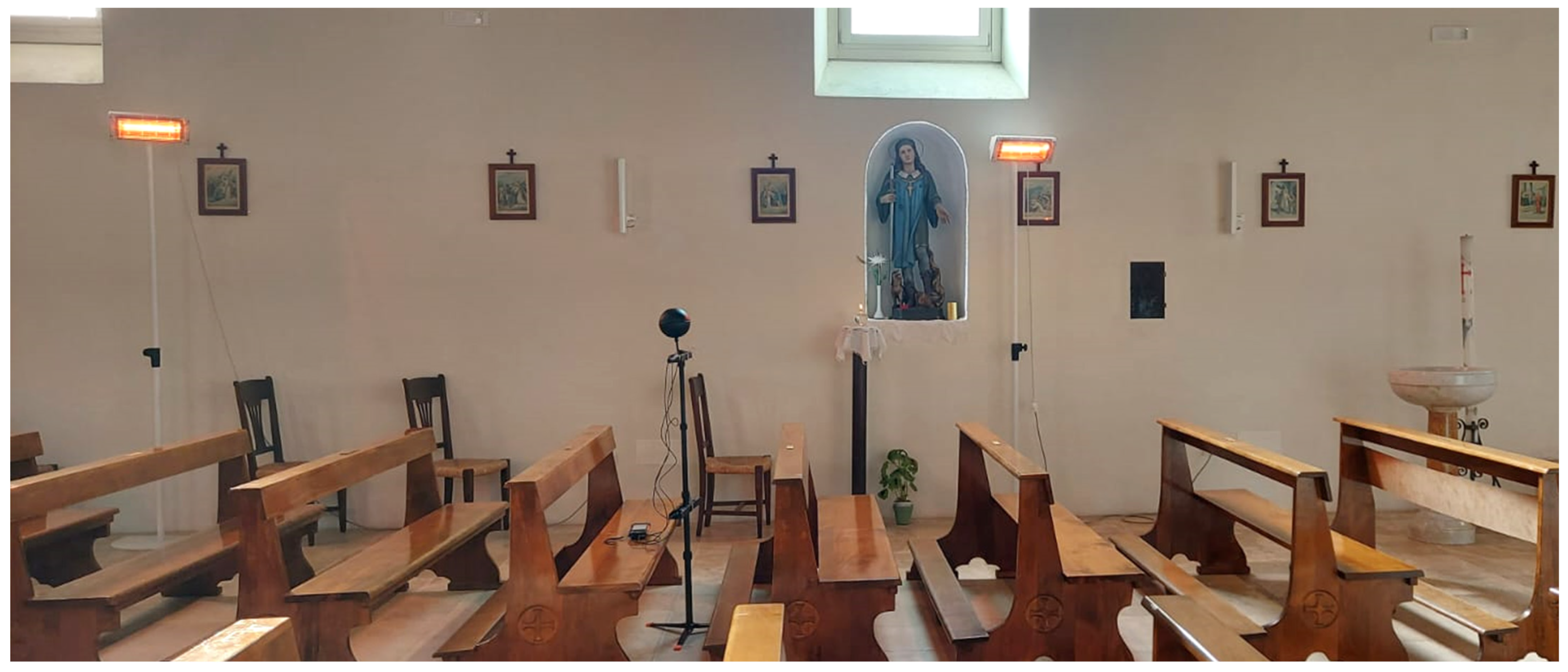
10], it was impossible to evaluate the benefits of the heating system present in the church, in terms of environmental comfort. Currently, the church is heated exclusively thanks to the infrared lamps placed along the nave (
Figure 9); the underfloor heating system realized during the retrofit works is not used as the customers of the church reports that the cost-benefit ratio to bring the heating system up to speed is not effective for the real usage period of the church (two hours, one day a week).
Therefore, the comfort improvement from this heating system is estimated through dynamic simulation using the validated model. In order to adequately simulate the user comfort in the area of the pew, due to retrofit intervention applied to the church during the post-earthquake restoration, it was necessary to identify and analyze in the model only the volumes of air actually heated by the added underfloor heating system, separating them with a virtual partitions from the rest of the hall (
Figure 10). The definition of separated zones within the church hall, allows to evaluate the comfort parameters separately within the zones themselves: in this way, it is possible to understand the benefits of underfloor heating system by locating the measurement of the parameters in the pertinent area of the room, thereby obtaining more realistic results. Subsequently, the results of the dynamic simulation for the church heated by localized underfloor heating in the pew were compared with the comfort monitoring data for the church heated by infrared lamps currently used (
Table 3).
The following evaluation was made only for Case ii, i.e., for the condition of worst discomfort detected in the previous analysis (
Table 1 and
Table 2: user seated, relaxed). The data comparison is shown below in
Table 3.
The table shows how the condition of discomfort related to case ii (users seated, met 1) improves slightly with the use of heating systems. In particular, the verification carried out thanks to the CBE comfort tool, shows these parameters in relation to the psychrometric diagram: it is possible to verify how the use of infrared lamps, while improving the indoor parameters, does not allow to reach the neutral sensation (
Figure 11: red point out of the blue comfort area); on the other hand, the simulation data for underfloor heating are the only ones to guarantee a neutral sensation (
Figure 12: red point in the blue area).
It is important to note that the comfort analyzed for all conditions is never compliant with ASHRAE Standard 55-2020 [
50], as the Clo value set equal to 2 and corresponding to winter clothing with an overcoat is not considered admissible by the standard for internal environments, but still reliable for the condition of a worship place.
Although underfloor heating is the only condition analyzed capable of guaranteeing user comfort, it should in any case be highlighted that the work, which is invasive from a material point of view and onerous from an economical point of view for the construction of the system, does not find a corresponding advantage in terms of improvement of thermo-hygrometric parameters. Furthermore, the functionality of the system which involves a slow start-up is not adequate for the current use of the church, and this is demonstrated by the customers’ choice to use the infrared lamps.
The analysis carried out in this work brings out the need to establish for particular places such as churches, with irregular and discontinuous use, good practices intervention that take into account not only the final efficiency of the intervention—in terms of both comfort and energy efficiency—but also and above all of the type of use of the structure (the legislation often not considered typical clothing during use, time, period and time of use, etc.).
A detailed analysis of the need for use in relation to the protection of the values that the restoration intervention must in any case guarantee, would open up the retrofit to a range of different solutions, possibly more flexible, less invasive and equally performing. An example of these systems could be radiant panels or infrared lamps to be applied externally under the benches or on the back of the seats [
7]: this system would maintain the benefit of localized heating (like floor panels) and at the same time guarantee the same advantages as the current infrared lamps (fast and flexible use).
6. Conclusions
The European Commission is investing heavily in issues related to the fight against climate change through the containment of consumption and, thus, carbon dioxide emissions. In the building industry, issues such as improving energy efficiency, reducing emissions and implementing comfort conditions, have mainly concerned the existing building stock. In countries such as Italy, the achievement of EU goals also requires attention for the historical buildings as well as religious buildings, which are normally characterized by values that must be preserved as they bear witness to the cultural expression of the people who generated them. The study of the state-of-the-art has shown that the challenges to be overcome and the research gaps to be filled are numerous and complex in the particular field of religious buildings. The present work aimed to contribute to the identification of some of the critical issues related to user comfort, with consequences on the energy consumption, highlighted in relation to changes in the way churches are used following reuse and restoration. The approach proposed in this paper was then validated through the application on the case-study of the church of San Vito in L’Aquila.
The results showed that:
- -
the use of systems exploiting thermal mass is not sustainable in environments with intermittent use, despite the fact that they are able to guarantee comfort conditions for users;
- -
careful knowledge of the conditions of use of the environments of religious buildings is essential to identify compatible and sustainable intervention strategies;
- -
it is appropriate to reflect in terms of “zoning” within religious buildings, differentiating the areas to be heated from those that do not require heating or that should not be disturbed, due to the presence of frescoes, paintings and artistic works in general;
- -
in relation to historical religious buildings, it is necessary to base any choice on the specific knowledge of the artefact, also passing through the systems that technology offers us today, such as software suitable for simulations in the field of cultural heritage and sensorial monitoring systems, differentiated according to the parameters to be controlled.
Paper results are extremely interesting as they highlight a lack in the current built heritage performance improvement related to the new building uses: in fact, energy analysis more often than not focus on savings obtainable both through interventions that improve the thermal properties of the historical envelope and through the installation of more performing thermal plants. On the other hand, the research highlights that if a more efficient system from an energy point of view (such as the case of underfloor heating in the S. Vito Church) is not consistent with the building type, its use loses effectiveness. This assumption may also be extended to the entire architectural heritage under retrofit and reuse interventions: in order to ensure a real optimization of the heritage buildings performance, activities of the occupants and environment fruition modes must have a priority role.
The study will be deepened in the future by implementing the number of case studies and investigation scenarios also involving the energy efficiency analysis.


