
Research on a New Plant Fiber Concrete-Light Steel Keel Wall Panel
Abstract
:1. Introduction
2. Materials and Methods
2.1. Rice Straw Fiber Concrete
2.1.1. Raw Materials and Preparation Process
2.1.2. Test Method
2.1.3. Mix Ratio
2.2. Thermal Performance of RS-LSWP
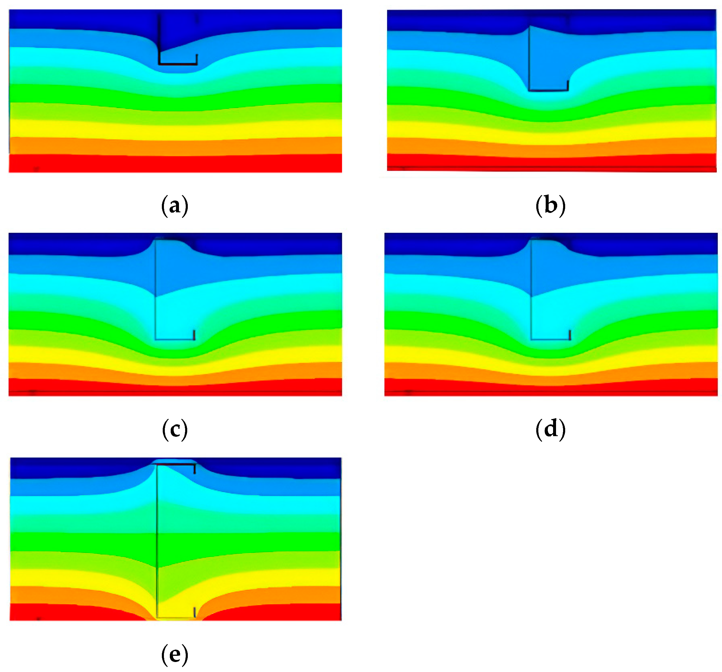
2.2.1. Computational Theory and Model Verification
2.2.2. Parameterization
3. Results and Discussion
3.1. Rice Straw Fiber Concrete
3.1.1. Compressive Strength
3.1.2. Tensile Strength
3.1.3. Thermal Conductivity
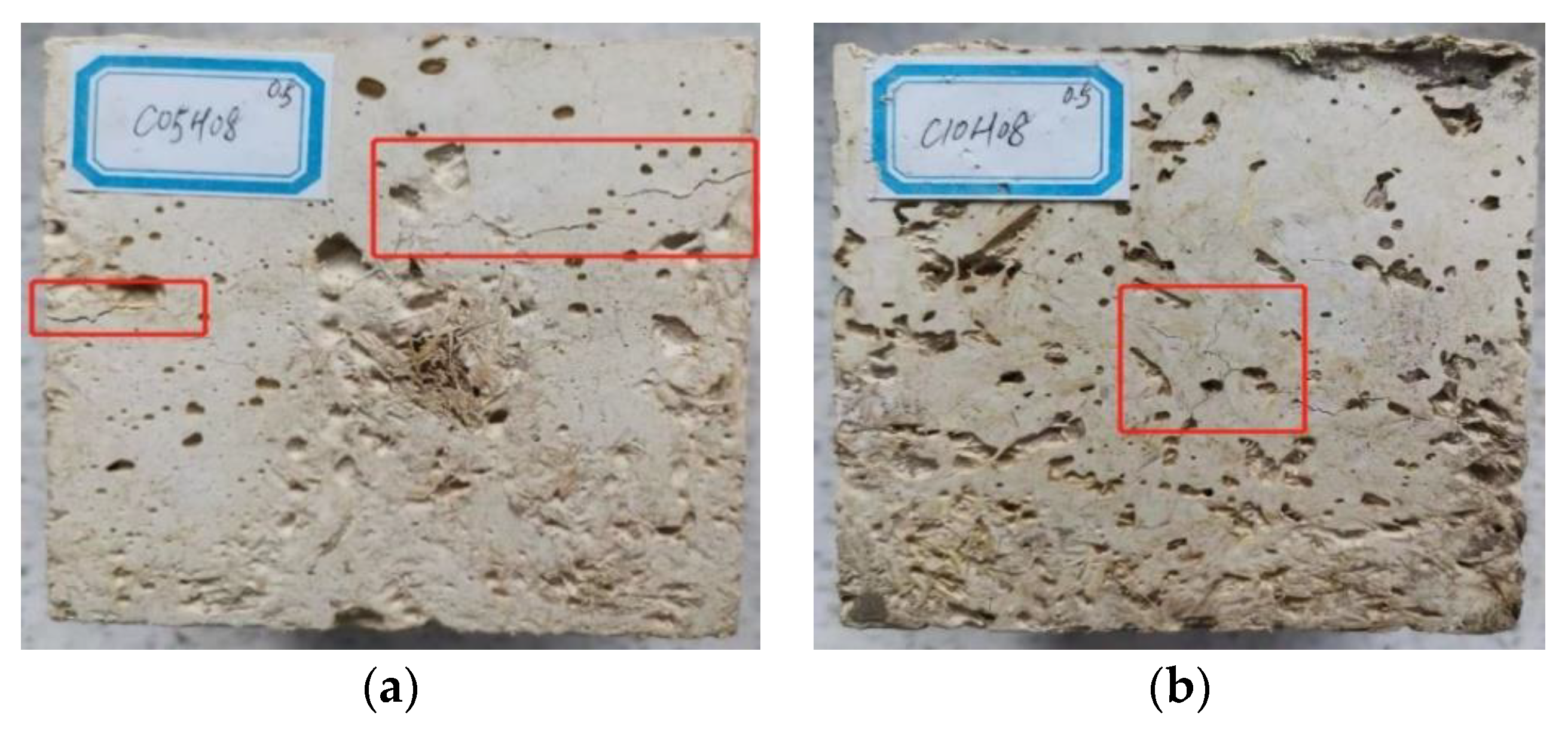
3.1.4. Density and Surface Cracks
3.2. Thermal Performance of RS-LSWP
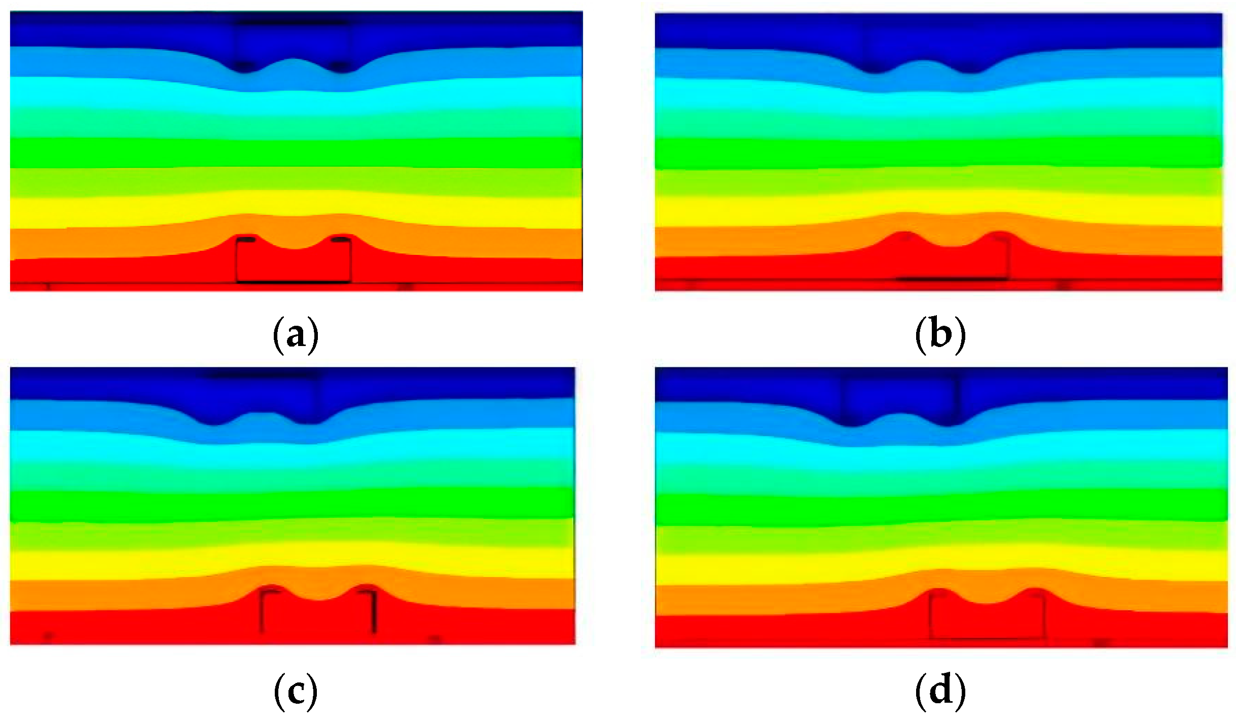
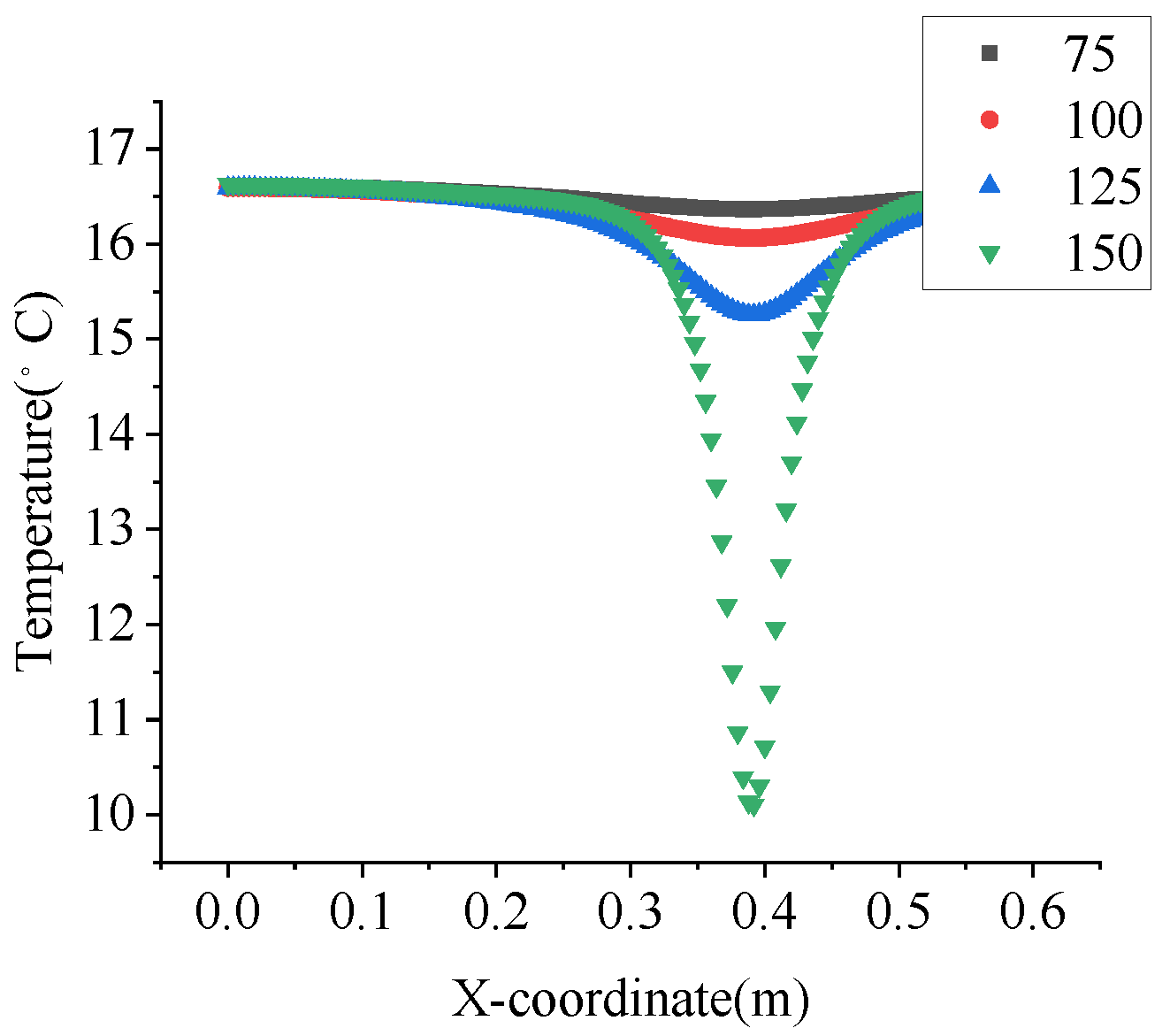
3.2.1. Type C
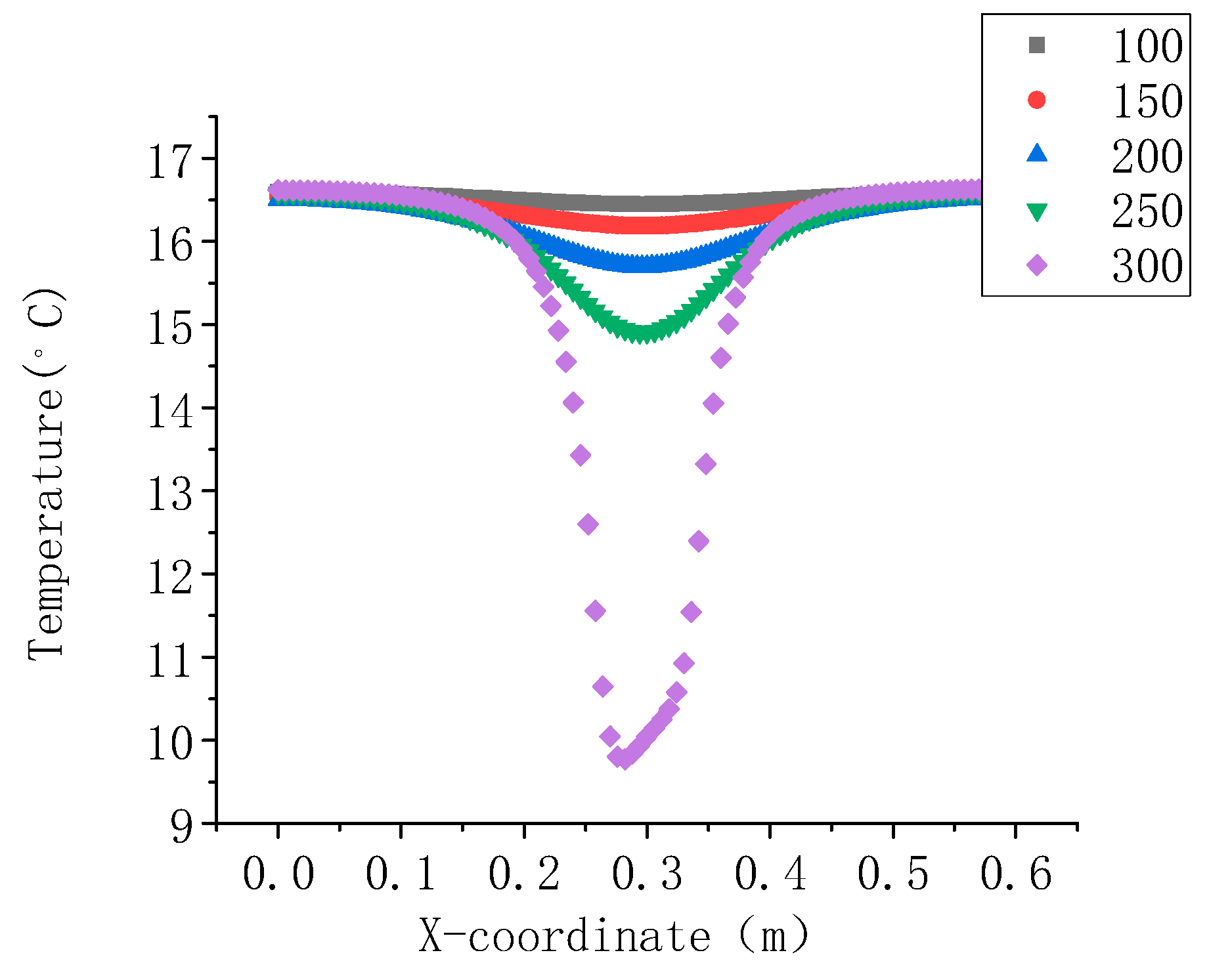
- Influence of different web widths on the thermal performance of RS-LSWP
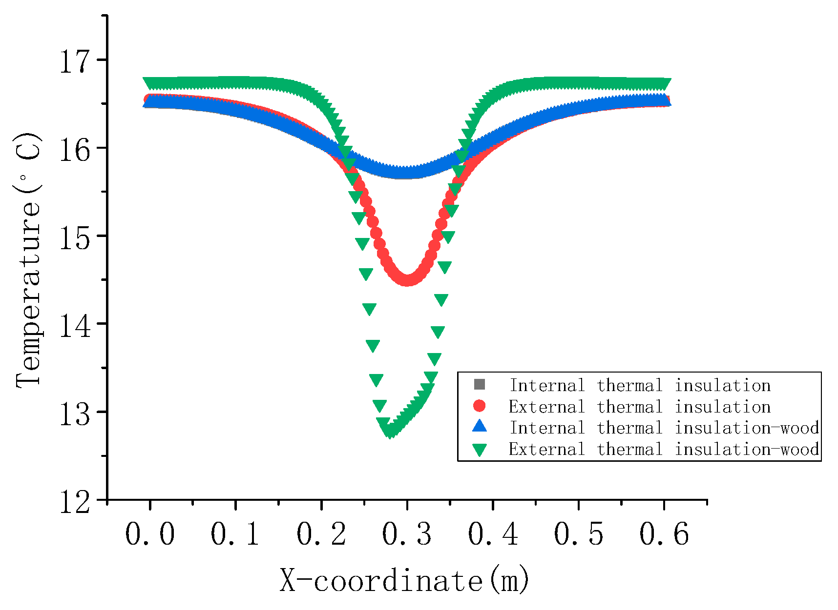
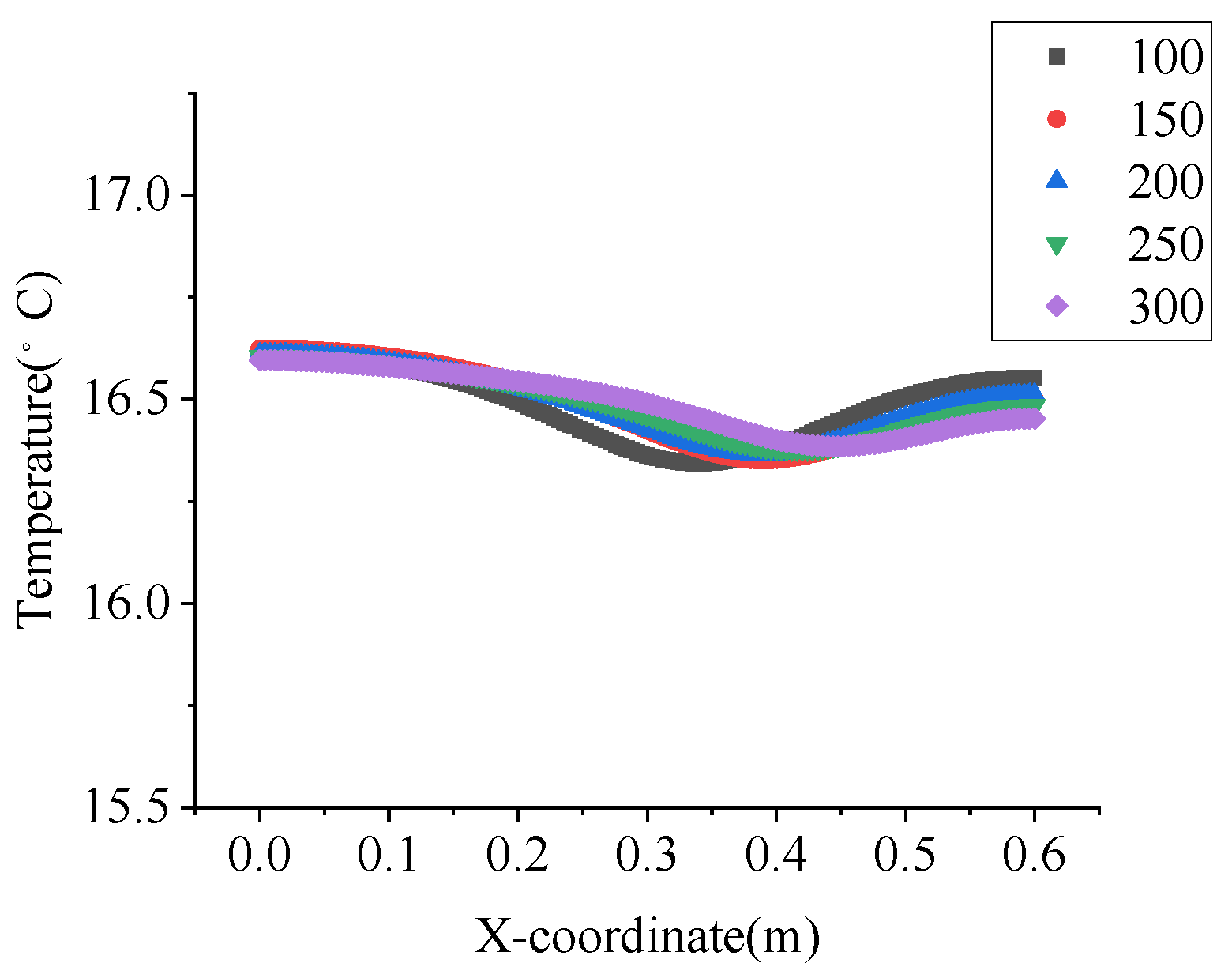
- Influence of different insulation forms on the thermal performance of RS-LSWP
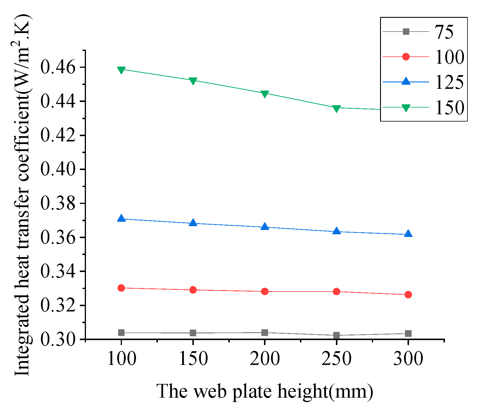
- Comprehensive heat transfer coefficient of RS-LSWP with different web widths and different insulation forms
3.2.2. Antitype C
- Influence of different flange heights on the thermal performance of RS-LSWP
- Influence of different offset distances on the thermal performance of RS-LSWP
- Comprehensive heat transfer coefficient analysis of wall panels with different flange heights and different offset distances
3.2.3. Type Z
- Influence of different web widths on the thermal performance of RS-LSWP
- Comprehensive heat transfer coefficient analysis of wall panels with different flange heights and different offset distances
3.2.4. Inverted Type Z
- Influence of different flange widths on the thermal performance of RS-LSWP
- Influence of different web widths on the thermal performance of RS-LSWP
- Comprehensive heat transfer coefficient analysis of wall panels with different web widths and flange heights
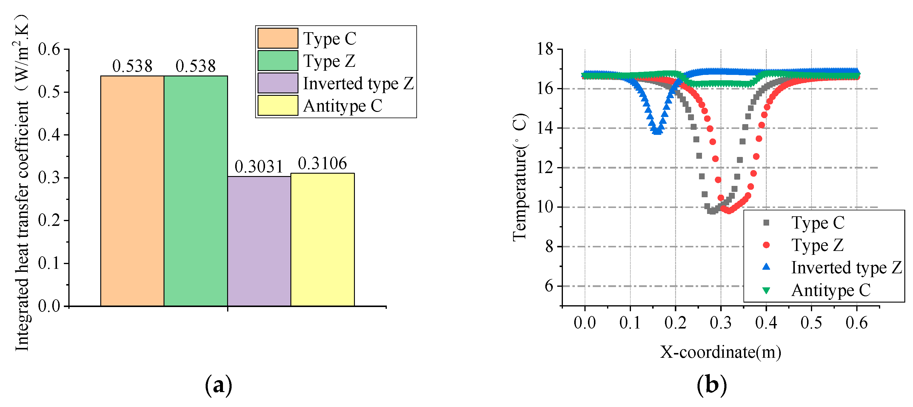
3.2.5. Comparison of Thermal Performance of Different Steel Keel Structures
3.3. Discussion
4. Conclusions
- The mechanical properties of RSFC can be improved by increasing the length of RS and the content of the modifier. The mechanical properties of RSFC decreased with the increase in straw content and with the mix of MgO and MgSO4. When RS content is 12%, the compressive strength, tensile strength, apparent density, and thermal conductivity of straw concrete are reduced significantly, and the crack can be avoided effectively. The 14-day strength of RSFC reached more than 85% of the final strength.
- The ratio of RSFC applied in RS-LSWP should be C05H12*(1.0). The standard compressive strength, tensile strength, and thermal conductivity of the mixture are 2.2 MPa, 0.64 MPa, and 0.0862 W/(m·K), respectively.
- The inverted type Z and the antitype C keel structure can reduce the comprehensive heat transfer coefficient and improve the temperature curve of the inner surface of the wall panel. The antitype C keel structure is most suitable for RS-LSWP.
Author Contributions
Funding
Institutional Review Board Statement
Informed Consent Statement
Data Availability Statement
Acknowledgments
Conflicts of Interest
References
- Franz, J.; Morse, S.; Pearce, J.M. Low-Cost Pole and Wire Photovoltaic Racking. Energy Sustain. Dev. 2022, 68, 501–511. [Google Scholar] [CrossRef]
- Syafiq, A.; Balakrishnan, V.; Ali, M.S.; Dhoble, S.J.; Rahim, N.A.; Omar, A.; Bakar, A.H.A. Application of Transparent Self-Cleaning Coating for Photovoltaic Panel: A Review. Curr. Opin. Chem. Eng. 2022, 36, 100801. [Google Scholar] [CrossRef]
- Liu, J.; Xie, X.; Li, L. Experimental Study on Mechanical Properties and Durability of Grafted Nano-SiO2 Modified Rice Straw Fiber Reinforced Concrete. Constr. Build. Mater. 2022, 347, 128575. [Google Scholar] [CrossRef]
- Rehman, M.S.U.; Umer, M.A.; Rashid, N.; Kim, I.; Han, J.-I. Sono-Assisted Sulfuric Acid Process for Economical Recovery of Fermentable Sugars and Mesoporous Pure Silica from Rice Straw. Ind. Crops Prod. 2013, 49, 705–711. [Google Scholar] [CrossRef]
- Mehta, P.K. Pozzolanic and Cementitious Byproducts as Mineral Admixtures for Concrete—A Critical Review; ACI Special Publication 79; American Concrete Institute: Farmington Hills, MI, USA, 1983; 46p. [Google Scholar]
- Roselló, J.; Soriano, L.; Santamarina, M.P.; Akasaki, J.L.; Monzó, J.; Payá, J. Rice Straw Ash: A Potential Pozzolanic Supplementary Material for Cementing Systems. Ind. Crops Prod. 2017, 103, 39–50. [Google Scholar] [CrossRef]
- Thomas, B.S.; Yang, J.; Mo, K.H.; Abdalla, J.A.; Hawileh, R.A.; Ariyachandra, E. Biomass Ashes from Agricultural Wastes as Supplementary Cementitious Materials or Aggregate Replacement in Cement/Geopolymer Concrete: A Comprehensive Review. J. Build. Eng. 2021, 40, 102332. [Google Scholar] [CrossRef]
- Abou-Sekkina, M.M.; Issa, R.M.; Bastawisy, A.E.-D.M.; El-Helece, W.A. Characterization and Evaluation of Thermodynamic Parameters for Egyptian Heap Fired Rice Straw Ash (RSA). Int. J. Chem. 2010, 2, 81. [Google Scholar] [CrossRef]
- Munshi, S.; Sharma, R.P. Utilization of Rice Straw Ash as A Mineral Admixture in Construction Work. Mater. Today Proc. 2019, 11, 637–644. [Google Scholar] [CrossRef]
- Pandey, A.; Kumar, B. Effects of Rice Straw Ash and Micro Silica on Mechanical Properties of Pavement Quality Concrete. J. Build. Eng. 2019, 26, 100889. [Google Scholar] [CrossRef]
- Agwa, I.S.; Omar, O.M.; Tayeh, B.A.; Abdelsalam, B.A. Effects of Using Rice Straw and Cotton Stalk Ashes on the Properties of Lightweight Self-Compacting Concrete. Constr. Build. Mater. 2020, 235, 117541. [Google Scholar] [CrossRef]
- Pandey, A.; Kumar, B. Evaluation of Water Absorption and Chloride Ion Penetration of Rice Straw Ash and Microsilica Admixed Pavement Quality Concrete. Heliyon 2019, 5, e02256. [Google Scholar] [CrossRef] [PubMed]
- Pandey, A.; Kumar, B. Investigation on the Effects of Acidic Environment and Accelerated Carbonation on Concrete Admixed with Rice Straw Ash and Microsilica. J. Build. Eng. 2020, 29, 101125. [Google Scholar] [CrossRef]
- Bories, C.; Borredon, M.-E.; Vedrenne, E.; Vilarem, G. Development of Eco-Friendly Porous Fired Clay Bricks Using Pore-Forming Agents: A Review. J. Environ. Manag. 2014, 143, 186–196. [Google Scholar] [CrossRef]
- Duppati, S.; Gopi, R. Strength and Durability Studies on Paver Blocks with Rice Straw Ash as Partial Replacement of Cement. Mater. Today Proc. 2022, 52, 710–715. [Google Scholar] [CrossRef]
- Singh, S.; Maiti, S.; Bisht, R.S.; Balam, N.B.; Solanki, R.; Chourasia, A.; Panigrahi, S.K. Performance Behaviour of Agro-Waste Based Gypsum Hollow Blocks for Partition Walls. Sci. Rep. 2022, 12, 3204. [Google Scholar] [CrossRef]
- Tachaudomdach, S.; Hempao, S. Investigation of Compression Strength and Heat Absorption of Native Rice Straw Bricks for Environmentally Friendly Construction. Sustainability 2022, 14, 12229. [Google Scholar] [CrossRef]
- Rajput, A.; Gupta, S.; Bansal, A. A Review on Recent Eco-Friendly Strategies to Utilize Rice Straw in Construction Industry: Pathways from Bane to Boon. Environ. Sci. Pollut. Res. 2022, 30, 11272–11301. [Google Scholar] [CrossRef] [PubMed]
- Ataie, F. Influence of Rice Straw Fibers on Concrete Strength and Drying Shrinkage. Sustainability 2018, 10, 2445. [Google Scholar] [CrossRef]
- Nguyen, C.V.; Mangat, P.S. Properties of Rice Straw Reinforced Alkali Activated Cementitious Composites. Constr. Build. Mater. 2020, 261, 120536. [Google Scholar] [CrossRef]
- Nazerian, M.; Sadeghiipanah, V. Cement-Bonded Particleboard with a Mixture of Wheat Straw and Poplar Wood. J. For. Res. 2013, 24, 381–390. [Google Scholar] [CrossRef]
- Karade, S.R.; Irle, M.; Maher, K. Assessment of Wood-Cement Compatibility: A New Approach. Holzforschung 2003, 57, 672–680. [Google Scholar] [CrossRef]
- Canovas, M.F.; Selva, N.H.; Kawiche, G.M. New economical solutions for improvement of durability of Portland cement mortars reinforced with sisal fibers. Mater. Struct. 1992, 25, 417–422. [Google Scholar] [CrossRef]
- Ma, L.F.; Kuroki, Y.; Eusebio, D.A.; Nagadomi, W.; Kawai, S.; Sasaki, H. Manufacture of bamboo cement composites. 1. Hydration characteristics of bamboo-cement mixtures. Mokuzai Gakkaishi 1996, 42, 34–42. [Google Scholar]
- Sorrel, S. On a new magnesium cement. C. R. Acad. Sci. 1867, 65, 102–104. [Google Scholar]
- Zhou, X.; Li, Z. Light-Weight Wood–Magnesium Oxychloride Cement Composite Building Products Made by Extrusion. Constr. Build. Mater. 2012, 27, 382–389. [Google Scholar] [CrossRef]
- Sglavo, V.M.; De Genua, F.; Conci, A.; Ceccato, R.; Cavallini, R. Influence of Curing Temperature on the Evolution of Magnesium Oxychloride Cement. J. Mater. Sci. 2011, 46, 6726–6733. [Google Scholar] [CrossRef]
- Chau, C.K.; Chan, J.; Li, Z. Influences of Fly Ash on Magnesium Oxychloride Mortar. Cem. Concr. Compos. 2009, 31, 250–254. [Google Scholar] [CrossRef]
- Deng, D. The Mechanism for Soluble Phosphates to Improve the Water Resistance of Magnesium Oxychloride Cement. Cem. Concr. Res. 2003, 33, 1311–1317. [Google Scholar] [CrossRef]
- Xiao, J.; Zuo, Y.; Li, P.; Wang, J.; Wu, Y. Preparation and Characterization of Straw/Magnesium Cement Composites with High-Strength and Fire-Retardant. J. Adhes. Sci. Technol. 2018, 32, 1437–1451. [Google Scholar] [CrossRef]
- Li, Y.; Yu, H.; Zheng, L.; Wen, J.; Wu, C.; Tan, Y. Compressive Strength of Fly Ash Magnesium Oxychloride Cement Containing Granite Wastes. Constr. Build. Mater. 2013, 38, 1–7. [Google Scholar] [CrossRef]
- Wang, J.; Zuo, Y.; Xiao, J.; Li, P.; Wu, Y. Construction of Compatible Interface of Straw/Magnesia Lightweight Materials by Alkali Treatment. Constr. Build. Mater. 2019, 228, 116712. [Google Scholar] [CrossRef]
- Dao, T.N.; van de Lindt, J.W. Seismic Performance of an Innovative Light-Gauge Cold-Formed Steel Mid-Rise Building. In Proceedings of the Structures Congress 2012, Chicago, IL, USA, 29–31 March 2012; American Society of Civil Engineers: Reston, VA, USA, 2012. [Google Scholar]
- Li, Z.; Guan, K. Research on Housing Industrialization and Necessity of Its Development. J. Harbin Univ. Civ. Eng. Archit. 1999, 98–102. [Google Scholar]
- Girard, J.; Tarpy, T. Shear Resistance of Steel-Stud Wall Panels Shear Resistance of Steel-Stud Wall Panels. In Proceedings of the 6th International Specialty Conference on Cold-Formed Steel Structures, St. Louis, MO, USA, 16–17 November 2020. [Google Scholar]
- He, B.-K.; Guo, P.; Wang, Y.-M. Experimental investigation on high strength cold-formed steel framing wall studs under axial compression loading. J. Xi’an Univ. Archit. Technol. 2008, 40, 567–573+579. [Google Scholar]
- Bian, J.; Cao, W.; Xiong, C. Experiment on the compression performance of composite wall of cold-formed steel and tailing microcrystalline foam glass slab. J. Harbin Inst. Technol. 2019, 51, 86–93. [Google Scholar]
- Qian, Z.; Pan, J.; Zhang, L. Research on Flexural Behavior of Light-Gauge Steel Stud Concrete Composite Wall Panels. Ind. Constr. 2020, 50, 32–37+4. [Google Scholar]
- Wu, J.; Wang, Q.; Li, B. A study on compressive properties of cold-formed thin-walled steel frame fly ash ceramsite concrete wallboard. New Build. Mater. 2018, 45, 97–100. [Google Scholar] [CrossRef]
- Lu, M.J. Thermal Optimization Strategy of External Wall in Low-Rise Light Steel Keel Structure Based on the Theory of Thermal Bridge. AMR 2013, 671–674, 2150–2153. [Google Scholar] [CrossRef]
- GBT50081-2019; Standard Test Method for Physical and Mechanical Properties Of Concrete. China Building Industry Press: Beijing, China, 2019.
- Wang, S.; Zhang, D.; Liu, G.; Wang, W.; Hu, M. Application of Hot-Wire Method for Measuring Thermal Conductivity of Fine Ceramics. Mater. Sci. 2016, 22, 560–564. [Google Scholar] [CrossRef]
- GB50176-2016; Code for Thermal Design of Civil Building. China Building Industry Press: Beijing, China, 2016.
- Li, F.; Li, J.; Xiao, M.; Ren, M. Impact Resistance of Lightweight Steel-Framed Foamed Concrete Composite Wall Panels. Bull. Chin. Ceram. Soc. 2022, 41, 68–75. [Google Scholar]


| Number | MgO/MgSO4/H2O ① | Modifier ② (%) |
|---|---|---|
| C05H08(0.5) | 8/1/20 | 0.5 |
| C10H08(0.5) | 8/1/20 | 0.5 |
| C15H08(0.5) | 8/1/20 | 0.5 |
| C05H08(1.0) | 8/1/20 | 1.0 |
| C05H10(1.0) | 8/1/20 | 1.0 |
| C05H12(1.0) | 8/1/20 | 1.0 |
| C05H12*(1.0) | 9/1/20 | 1.0 |
| Computational Model | Theoretical Calculation (W/m2·K) | Finite Element Simulation (W/m2·K) | Error (%) |
|---|---|---|---|
| 0.5 m single-story wooden structure | 0.322 | 0.327 | 1.5 |
| Double timber structure with rock wool | 0.1509 | 0.1509 | 0 |
| Number | Strength (Mpa) |
|---|---|
| C05H08(0.5) | 1.74 |
| C05H08(1.0) | 1.98 |
| C05H10(1.0) | 1.68 |
| C05H12(1.0) | 1.42 |
| C05H12*(1.0) | 0.64 |
| Number | Thermal Conductivity (W/(m·K)) |
|---|---|
| C05H08(1.0) | 0.617 |
| C05H10(1.0) | 0.600 |
| C05H12*(1.0) | 0.0862 |
| Composition | Content (kg/m3) |
|---|---|
| Rice straw | 81 |
| Husk | 27 |
| Magnesium oxide | 340 |
| MgSO4•7H2O | 235 |
| Modifier | 2.65 |
Disclaimer/Publisher’s Note: The statements, opinions and data contained in all publications are solely those of the individual author(s) and contributor(s) and not of MDPI and/or the editor(s). MDPI and/or the editor(s) disclaim responsibility for any injury to people or property resulting from any ideas, methods, instructions or products referred to in the content. |
© 2023 by the authors. Licensee MDPI, Basel, Switzerland. This article is an open access article distributed under the terms and conditions of the Creative Commons Attribution (CC BY) license (https://creativecommons.org/licenses/by/4.0/).
Share and Cite
Wu, Y.; Wu, Y.; Wu, Y. Research on a New Plant Fiber Concrete-Light Steel Keel Wall Panel. Sustainability 2023, 15, 8109. https://doi.org/10.3390/su15108109
Wu Y, Wu Y, Wu Y. Research on a New Plant Fiber Concrete-Light Steel Keel Wall Panel. Sustainability. 2023; 15(10):8109. https://doi.org/10.3390/su15108109
Chicago/Turabian StyleWu, Yuqi, Yunqiang Wu, and Yue Wu. 2023. "Research on a New Plant Fiber Concrete-Light Steel Keel Wall Panel" Sustainability 15, no. 10: 8109. https://doi.org/10.3390/su15108109