Article

Crashworthiness and Failure Analyses of FRP Composite Tubes under Low Velocity Transverse Impact

1
School of Aerospace Engineering and Applied Mechanics, Tongji University, Shanghai 200092, China
2
School of System Design and Intelligent Manufacturing (SDIM), Southern University of Science and Technology, Shenzhen 518055, China
*
Authors to whom correspondence should be addressed.
Sustainability 2023, 15(1), 56; https://doi.org/10.3390/su15010056
Submission received: 26 October 2022 / Revised: 5 December 2022 / Accepted: 15 December 2022 / Published: 21 December 2022
(This article belongs to the Special Issue Advanced Composites and Sustainability)

Abstract

:
Currently, FRP composite tubes are drawing increasing attention in many industrial applications, due to their excellent mechanical and lightweight properties, with reduced energy consumption and enhanced sustainability. This study investigates the failure mechanisms and crashworthiness performance of glass and carbon fibre reinforced polymer (GFRP and CFRP) composite tubes under low velocity transverse impact. Finite element methods were developed to establish numerical models to predict the failure responses of FRP composite tubes with a complex ply sequence of both woven and unidirectional layers. In the modelling, continuum damage mechanics and cohesive zone method were used to calculate the intralaminar and interlaminar failure behaviours, respectively, in FRP composite tubes. The numerical models were validated by corresponding experiments, and the effects of the impact energy and material type were investigated. The experimental results show that the initial impact energy does not significantly affect the specific energy absorption (SEA) and peak force (PF) of GFRP composite tubes, and the SEA and PF are generally around 0.5 kJ/kg and 600 N, respectively, when the impact energy varies from 10 J to 50 J. Failure mechanism analyses show that GFRP tubes and CFRP tubes with totally unidirectional plies present global bending deformation with significant matrix damage, and CFRP tubes with “hybrid layer type” exhibit local penetration with severe fibre and matrix damage. The crashworthiness analyses indicate that CFRP tubes perform better in SEA while GFRP tubes possess smaller PF when subjected to low velocity transverse impact.

1. Introduction

In recent years, adopting sustainable materials, either in engineering industries or in daily life, has become common sense to curb carbon emissions and climate change [1]. Fibre reinforced polymer (FRP) composite material is one important candidate among sustainable materials due to the lower environmental pollution in its production. It has been widely used in a variety of industrial domains, such as aeroplanes [2] and automobiles [3]. In addition, due to their low carbon emission, superior specific strength, stiffness, and excellent energy absorption capacity, FRP composites have increasingly drawn substantial attention. Additionally, FRP composite tubes are common components and can resist electrochemical corrosion, making them more sustainable than steel in particular environments [4]. As such, considerable experimental and numerical studies have been focused on the quasi-static and dynamic axial crushing of FRP composite tubes to investigate their mechanical properties and crashworthiness for engineering applications [5,6,7,8,9]. However, the transverse impact of FRP composite tubes is still under-reported, though they are commonly seen in engineering applications [10,11,12].
Transversal impact responses of composite tubes made of glass fibre reinforced polymers (GFRP) or carbon fibre reinforced polymers (CFRP) have been drawing increasing attention, with various relevant investigations [13,14,15,16] conducted. For instance, Wu et al. [17] investigated the transverse impact response of CFRP composite tubes with different ply sequences, with numerical and experimental approaches. Deniz et al. [18] experimentally studied the effects of the tubular diameter and initial impact energy on the failure behaviours of GFRP tubes. Sun et al. [19,20] characterised the quasi-static lateral crushing behaviours of circular GFRP and CFRP tubes with different geometric configurations. However, most current studies have only accounted for transverse impact behaviours of either GFRP or CFRP composite tubes, and most numerical models have only considered composite tubes with either unidirectional or woven ply. However, the “hybrid layer type” [19,20] FRP tubes, possessing both unidirectional and woven plies, are common and advantageous [19,20], but only a few numerical works are available.
In this study, we develop finite element models to perform the crashworthiness analysis and to predict the failure responses of “hybrid layer type” FRP tubes under low velocity transverse impact. First, low velocity transverse impact experiments on GFRP tubes were performed under different initial impact energies. Then, a comparative study was conducted for GFRP tubes, CFRP tubes with only unidirectional layers (CFRP-U) and CFRP tubes comprising both woven and unidirectional layers (CFRP-W), under the same initial impact energy (i.e., 50 J). Accordingly, numerical models based on the finite element method (FEM) were established to consider the intralaminar and interlaminar damage mechanisms of these FRP tubes. The FEM models were validated with the experimental results in terms of the force-displacement curves, failure morphologies and crashworthiness indexes.

2. Experiments

In this study, the GFRP tubes were made from unidirectional (Code 120) and woven (Code 7781) layers of E-glass fibre prepreg epoxy (Newport 301) by roll-wrapping and autoclave curing, and the layups were [(0/90)/0/90/(0/90)] with a fibre volume fraction of ~60%. The CFRP tubes were made from unidirectional and woven layers of carbon fibre (TR50S) prepreg epoxy (Newport 301) by roll-wrapping and autoclave curing, and the fibre volume fraction of cured specimens was 60%. Two kinds of CFRP tubes were used in this study. The CFRP tubes with only unidirectional plies, i.e., CFRP-U, were sequenced with [03/45/−45/90/45/−45/03], and the CFRP tubes with both woven and unidirectional layers, i.e., CFRP-W, were plied with [03/902/03/(0/90)]. The inner diameters of all FRP tubes were 50.8 mm, while by microscopic measurements, the nominal thicknesses of unidirectional and woven layers of GFRP tubes were 0.127 mm and 0.254 mm, and that of unidirectional and woven layers of CFRP tubes was 0.15 mm and 0.3 mm, respectively. Both CFRP tubes had the same number of unidirectional 0° plies, but the most apparent difference in lay-up configurations was that the outer layer of CFRP-W was a plain-woven ply. The specimens with their ply sequences of GFRP, CFRP-U and CFRP-W tubes are illustrated in Figure 1.
In reference to previous studies [5,17,21,22], the transverse impact tests for the CFRP and GFRP tubes were conducted using a drop tower system. Since the impactor mass was fixed at 5.482 kg, the impact tests under varying impact energies from 10 to 50 J were set up by adjusting velocities within 1–10 m/s to guarantee that the impact velocity was within the low velocity impact scope, and relevant impact setup parameters are listed in Table 1. The specimens of the FRP tubes were restrained via a fixture, and then a hemispherical steel impactor with a diameter of 12.5 mm was used to impact the specimen at different velocities (or energies). A hole was drilled in the centre of the fixture to protect the impactor of the impact testing machine. In addition, four feed screws were used to fix the specimens, as shown in Figure 2a. During the testing process, the impact force and displacement data were recorded, and those tubes’ failure process was captured through a recording system with a high-speed camera. The sampling frequency of the force sensor was set 200 kHz, and the moving-average filter [23] with a window size of 20 was used to filter the force data.
For the GFRP tubes, the initial energy was used. Two indicators were used to assess the crushing performance of the composite tubes [24]. Initially, the energy absorption (EA) can be integrated based on the force–displacement curve as follows.
EA = 0 d m a x F ( s ) d s = F m d m a x
where F(s) is the resistive force of the tube as a function of displacement s during the crushing process, F m is the average resistive force and d m a x is the crushing distance. Meanwhile, the peak force (PF), can also be extracted from force–displacement curves to evaluate the crashworthiness performance of FRP tubes.
Another index is the specific energy absorption (SEA) which expresses absorbed energy by a structure per unit mass. The SEA is given by:
SEA = E A m
In the crashworthiness analysis, the greater the SEA and the smaller the PF, the better the crashworthiness performance.

3. Numerical Analysis

3.1. Constitutive Models

Currently, continuum damage mechanics (CDM) [25] are usually utilised to calculate the intralaminar and interlaminar failure behaviours of FRP composites [25]. As such, the CDM-based approach was applied to employ the user-defined subroutine VUMAT of Abaqus software to simulate and predict the damage behaviours of CFRP and GFRP tubes under low velocity transverse impact [26]. The damage initiation criteria and evolution law for intralaminar failure are basically presented in Appendix A. For the interlaminar delamination, the cohesive zone method (CZM) was utilised in this study [25]. By using the CZM, at the beginning, the damage initiation is triggered when the contact stress ratios reach 1 according to a quadratic nominal stress criterion. Then, the evolution law (a mixed-mode fracture criterion based on the Benzeggagh–Kenane method [27] develops in a linear softening approach after meeting the initiation law to evaluate the fracture mechanism. More details on CZM can be referred in many previous publications [25]. To sum up, the CDM [28] was used to model the intralaminar failure while the CZM was utilised to model the interlaminar failure of FRP composite tubes. In terms of the material properties, the intralaminar and interlaminar parameters of both CFRP-U and CFRP-W tubes were directly adopted from our previous study [24]. For the GFRP tubes, the material parameters for numerical modelling are presented in Table 2. The Young’s modulus and material strength of E-glass/epoxy unidirectional layers were directly adopted from [29,30], while the fracture energies, e.g., longitudinal fracture energy (350 KJ/m2), etc., of the unidirectional layers were defined based on those of glass fibre composites [31]. The elastic properties of E-glass/epoxy woven layers were adopted from [32], while the fracture energies were adopted from those of GFRP woven fabrics [20]. The GFRP tubes’ interlaminar strength and toughness were defined based on [33], as shown in Table 2.

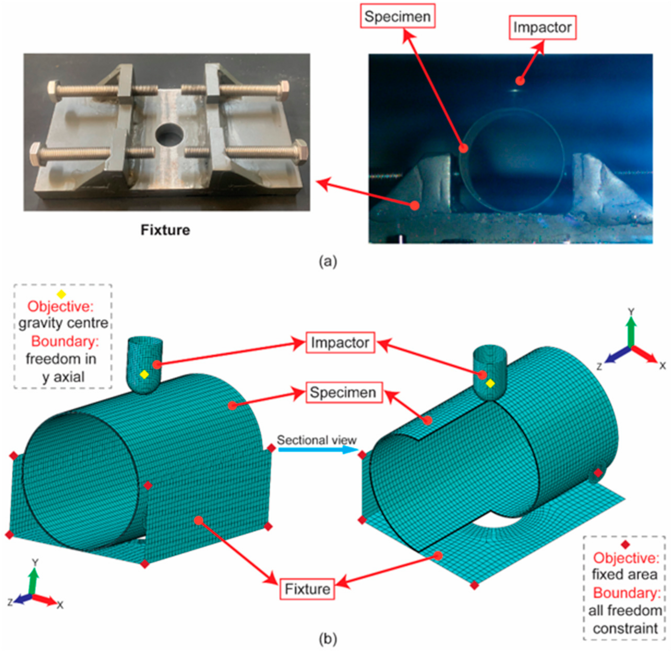
3.2. Description of Models

The FEM models were established for the impactor, the FRP specimens and the fixture in Abaqus/CAE [26]. The unidirectional and woven layers of the FRP tubes were modelled using continuum shell elements with reduced integration (SC8R) [26] and all interfaces between layers were modelled using the “cohesive contact” [26]. According to Figure 2a, to meet the actual condition, the fixture and four screws were built using discrete rigid elements to fix the specimens in the FEM model. Figure 2b presents the meshed models with the boundary conditions. After mesh convergence analysis, a uniform rectangular mesh of 2 mm × 1.6 mm was adopted for the FRP tubes. Additional sensitivity analysis was performed on A global element size of 2 mm was adopted for the plates of a fixture, and a global element size of 0.8 mm was adopted for the impactor and screw plate. A general contact based on penalty [26] at the tangential direction and hard contact methods [26] at normal was applied in the FEM model to calculate material interactions, and the friction coefficient was defined as 0.3 [34]. For the impactor, in accordance with experiments, different initial impact velocities or energies were applied. For the numerical results, the outputting frequency was ~50 kHz, and the moving-average filter with a window size of 5 was used to filter the outputting force to eliminate noise.

4. Result and Discussion

4.1. Effect of Impact Energy

In general, the initial impact energy may significantly affect energy absorption [35]. Three magnitudes of impact energies at 10 J, 30 J and 50 J were used to research the transverse impact damage behaviours of GFRP tubes, to assess the effect of impact energy.
The force-displacement curves of the GFRP tubes under different initial impact energy are exhibited in Figure 3. The figure shows that, generally, the force tends to reach the peak at ~11 mm by experiments and at ~12 mm by FEM. After that, the force begins to oscillate dramatically.
A further comparative study for the SEA and PF of GFRP tubes subjected to three magnitudes of impact energies is shown in Figure 4. The figure shows that the errors between the results of experiments and FEM are basically acceptable. PF varies slightly with the impact energies. The PF is ~600 N by both experiments and FEM. The values of PF decrease and the values of SEA increase with the increment of impact energy in the FEM results, but the amplitude does not change significantly. For instance, the difference in the SEA and PF of GFRP tubes between 10 J and 50 J by experiments are ~6%, respectively. Both methods indicate that the impact energy does not significantly affect the PF and SEA.
The experimental and numerical results in terms of failure morphologies of GFRP composite tubes at 50 J impact energy are depicted in Figure 5. Note that the stress condition is unclear from this viewpoint such that the specific stress analysis results are presented subsequently. Obviously, within the low velocity impact scope, the effect of impact energy plays an insignificant role in determining the crashworthiness performance and failure behaviours of GFRP tubes when subjected to transverse impact. Hence, the failure morphologies of GFRP tubes at 50 J were chosen to typically illustrate the failure responses of GFRP tubes under the transverse impact. By simulation, from Points A to B, the GFRP tubes were damaged progressively. Sharp stresses were only observed at the contact between the impactor and the specimen. From Points B to C, intralaminar failure occurs. When combined with Figure 3, we find that the impact force reaches a peak at the moment of intralaminar failure. Afterwards, from Points C to D, the resistant force oscillates, where large deformations and fracture zones are continuously enlarged, with a noticeable fracture line [20] in the upper area of the tube when reaching Point D. The fluctuations in the force–displacement curves and SEA in between the experiments and FEM were observed, which could be explained as follows. The CDM method can be convenient to describe a series of primary damage modes and non-linear behaviours of the composites, i.e., the fibre fracture, matrix cracking, and even the matrix plasticity. However, certain minor damage behaviours, such as fibre local buckling, fibre pulling out, matrix local cracking, etc., cannot totally be conveyed by the reduction of damage variables. Another reason for the difference may be caused by slight variations in material properties. Even though the material properties defined in the numerical model are the same as those reported in the references, the manufacturing conditions for specimens might be varied, which may cause slight differences in material properties, consequently resulting in a slight variation between the numerical and experimental results.
Figure 6 shows the corresponding intralaminar failure mechanisms (where 0 denotes undamaged and 1 denotes damaged material) of the GFPR tube at an initial transverse impact energy of 50 J with respect to Point D of Figure 5. The shear damage is not predominant, which agrees with the conclusions from other literature [24], so the shear damage is not presented. By comparison, the transverse traction and transverse compression damages are more severe than the longitudinal traction and longitudinal compression damages (where “transverse” means the circumferential direction while “longitudinal” means the direction parallel to the Z direction).

4.2. Effect of Material Type

Further, the effect of material type, i.e., GFRP, CFRP-U and CFRP-W tubes, on the failure mechanisms when subjected to low velocity transverse impact with the same impact energy of 50 J was investigated, using the FEM models described in Section 3.
Figure 7 compares the force–displacement curves obtained from the experimental tests and numerical simulations for these three FRP tubes. Basically, the FEM results well match the experiments, showing that the force of CFRP-U tubes increases rapidly at the very beginning; after that it begins to oscillate and the tubes become damaged. When the force continually increases and reaches a peak at ~2000 N by experiment and ~1400 N by FEM, it then decreases abruptly, with reduced energy absorption. For the CFRP-W tubes, by both experimental and FEM results, the force quickly increases until the displacement reaches ~10 mm. Following this, the force drops significantly. Obviously, the GFRP tubes show the lowest stiffness when compared to the other two types of CFRP tubes.
Furthermore, Figure 8 depicts the SEA and PF for three FRP tubes by both experiment and FEM. By experimental analysis, the PF of the GFRP tube is 31% that of the CFRP-U but the SEA value of the GFRP is 62% that of the CFRP-U. On the other hand, the PF of the CFRP-U tube is 12% greater than that of the CFRP-W tube, while the SEA of the CFRP-U is 32% greater than that of the CFRP-W specimen. This indicates that GFRP tubes have a potential or excellence in crashworthiness applications with respect to the low velocity transverse impact.
The failure process and mechanisms of GFRP tubes when subjected to transverse impact with an initial energy of 50 J have already been discussed in Figure 5 and Figure 6, respectively, then we can have a further investigation of the other two categories of CFRP tubes. Figure 9 depicts the failure morphologies of the CFRP-U composite tubes. From Points A to B, a distinct but slight deformation with materials failure can be captured in both experiments and FEM. Subsequently, significant fracture occurs with large fronds observed in experimental and numerical results at Point C, indicating the accuracy of the FEM models. Finally, at Point D, severe deformations with fractures of the CFRP-U tubes were seen.
Figure 10 shows the damage mechanisms of the CFRP-U tube at Point D. The 1st, 4th, 6th and 11th layers (i.e., 0°, 45°, 90°, 0° plies) were selected to analyse the damage mechanisms of CFRP-U tubes. It is evident that transverse traction damage (matrix tensile damage) is the primary failure mode. This is because, when under such a global bending situation, the hoop tension of the tube directly results in matrix cracking in the outermost three layers of the 0° ply sequence (parallel to the Z axis).
Figure 11 depicts failure morphologies of CFRP-W composite tubes by both experiment and FEM when subjected to transverse impact with an initial energy of 50 J. As compared to the GFRP and CFRP-U tubes, the failure morphologies of the CFRP-W tubes are different. The impactor directly penetrates the CFRP-W tubes, as captured in both experimental and numerical results, which is also the reason for the rapid force decrease depicted in Figure 7c. Unlike the CFRP-U tubes, there is no fracture line in the upper area of the CFRP-W tubes.
The failure mechanisms of the CFRP-W tube at Point D of Figure 11 are illustrated in Figure 12. Note that the 1st, 4th, 6th and 9th layers (i.e., 0°, 90°, 0°, 0°/90° plies) were selected to demonstrate the damage mechanisms of CFRP-W tubes. Apparently, aggravatedly damaged elements appear at the area near the penetration hole, while transverse traction (i.e., matrix damage) of the innermost layer leads to an extended strip at the bottom area of CFRP-U tube, due to severe contact between the tube and fixture plate. Furthermore, it is evident that severe transverse compression damage mode occurs at the contact location between the impactor and upper area of CFRP-W tube, especially at the 0°/90° layer.
The von Mises stresses of FRP tubes at Point D (i.e., 25 mm) are shown in Figure 13a. In order to inspect the interlaminar failure mechanisms of FRP composite tubes, several representative layers were used, as shown in Figure 13b. Apparently, the interlaminar damage behaviours can be observed as indicated by marks 1, 2, 3 and 4. Generally, the interlaminar damage response is insignificant. It is evident that these three types of FRP tubes have different deformation behaviours. Overall, the GFRP tubes and the CFRP tubes with totally unidirectional plies present global bending deformation behaviours, while the CFRP tubes with hybrid woven and unidirectional layers exhibit local penetration, which can be similarly seen in situations of CFRP panels with woven layers when subjected to in-plane localised crushing [31].

5. Conclusions

In this study, we have applied both experimental and numerical methods to analyse the crashworthiness performance and failure behaviours of FRP composite tubes under low velocity transverse impact. The key remarks are as follows:
(1)
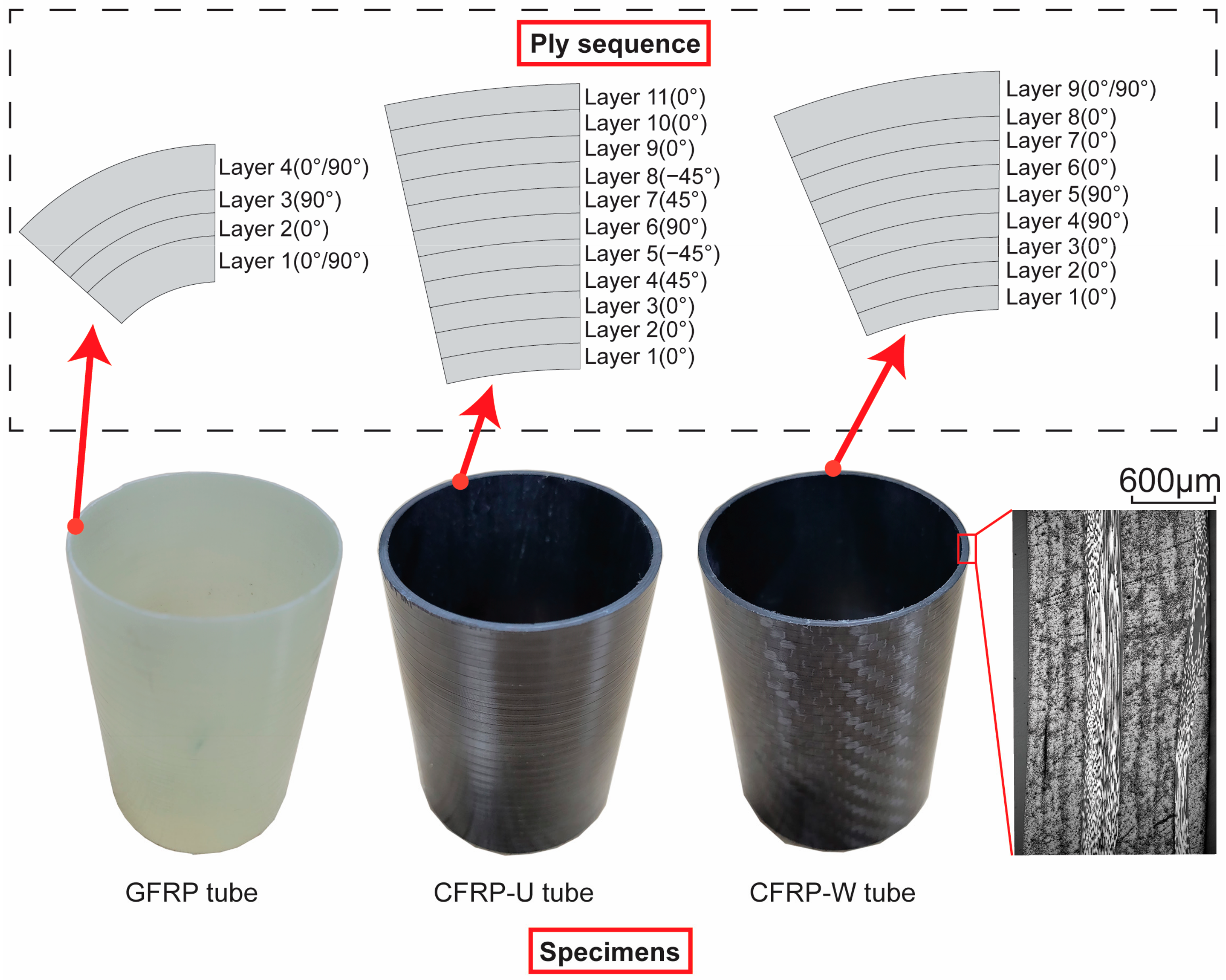
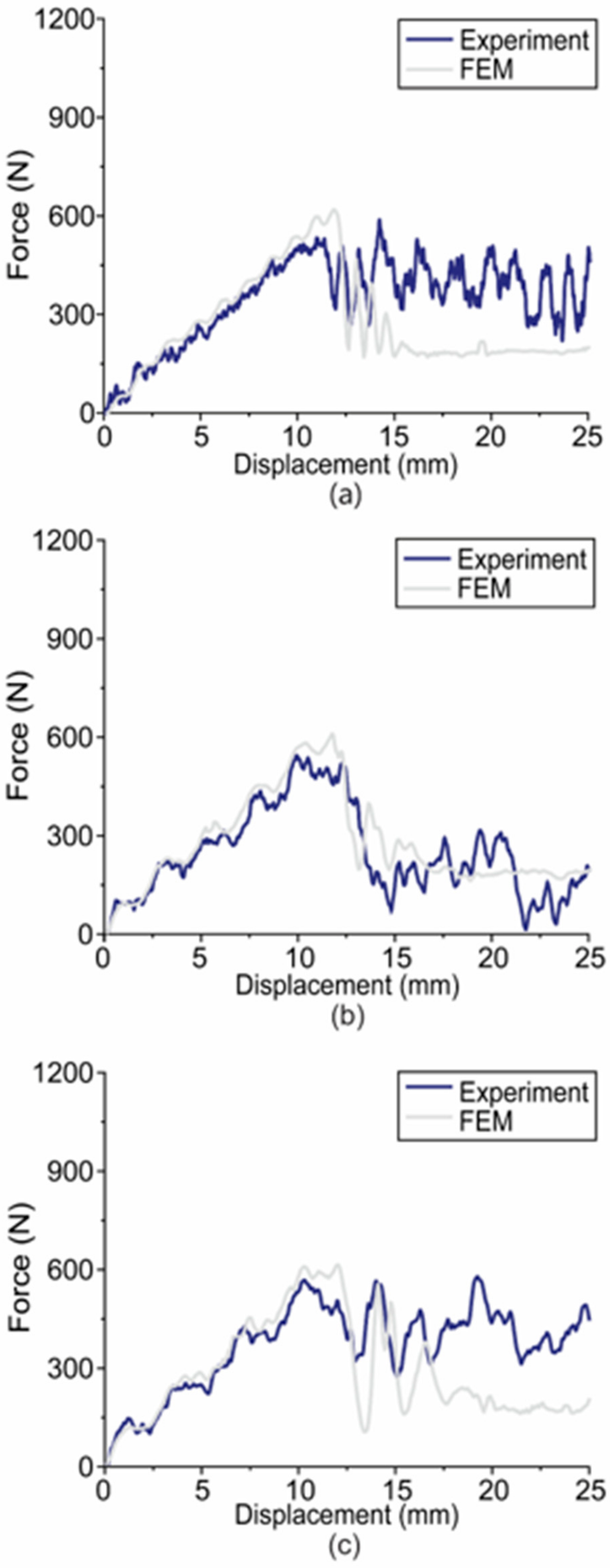
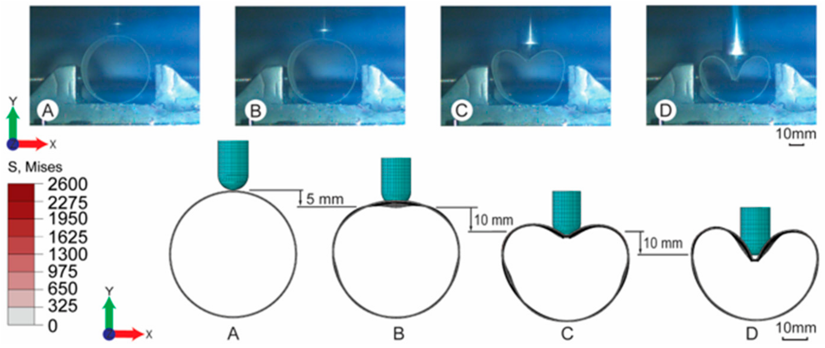
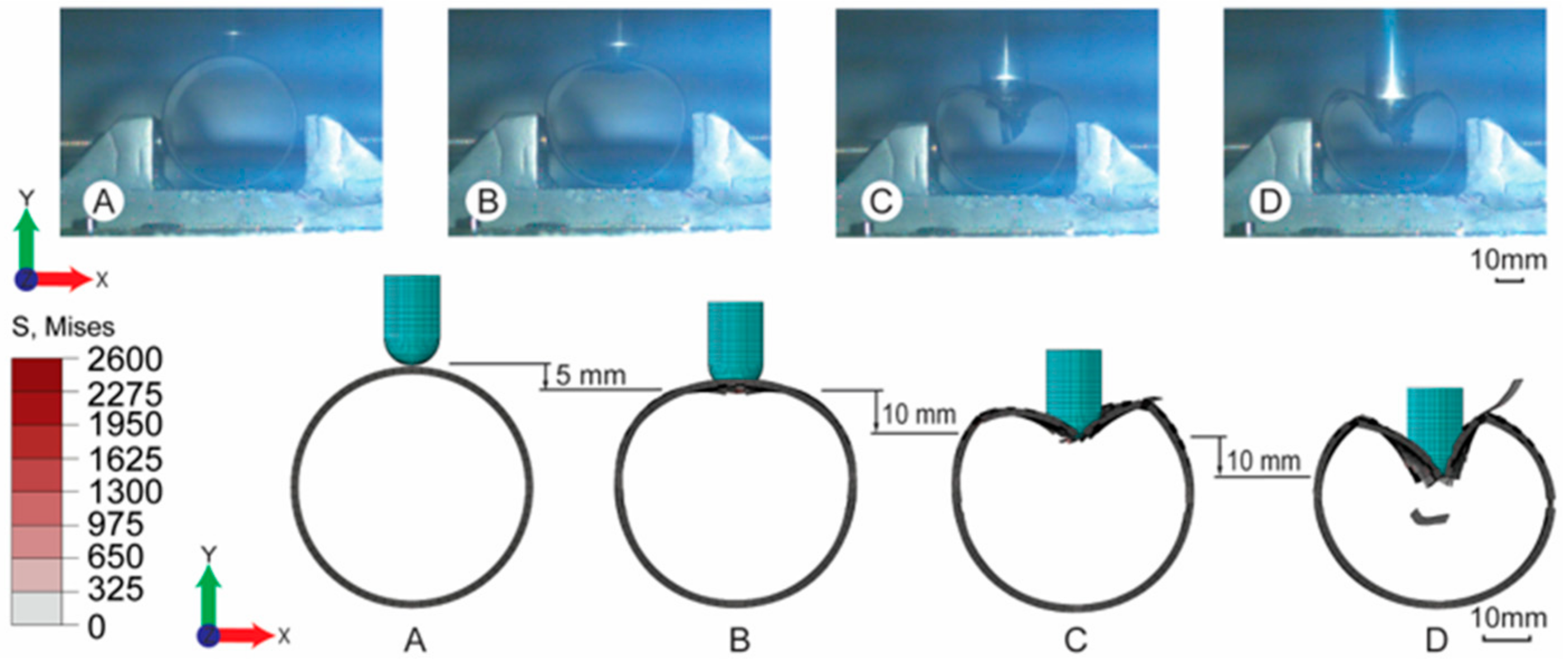
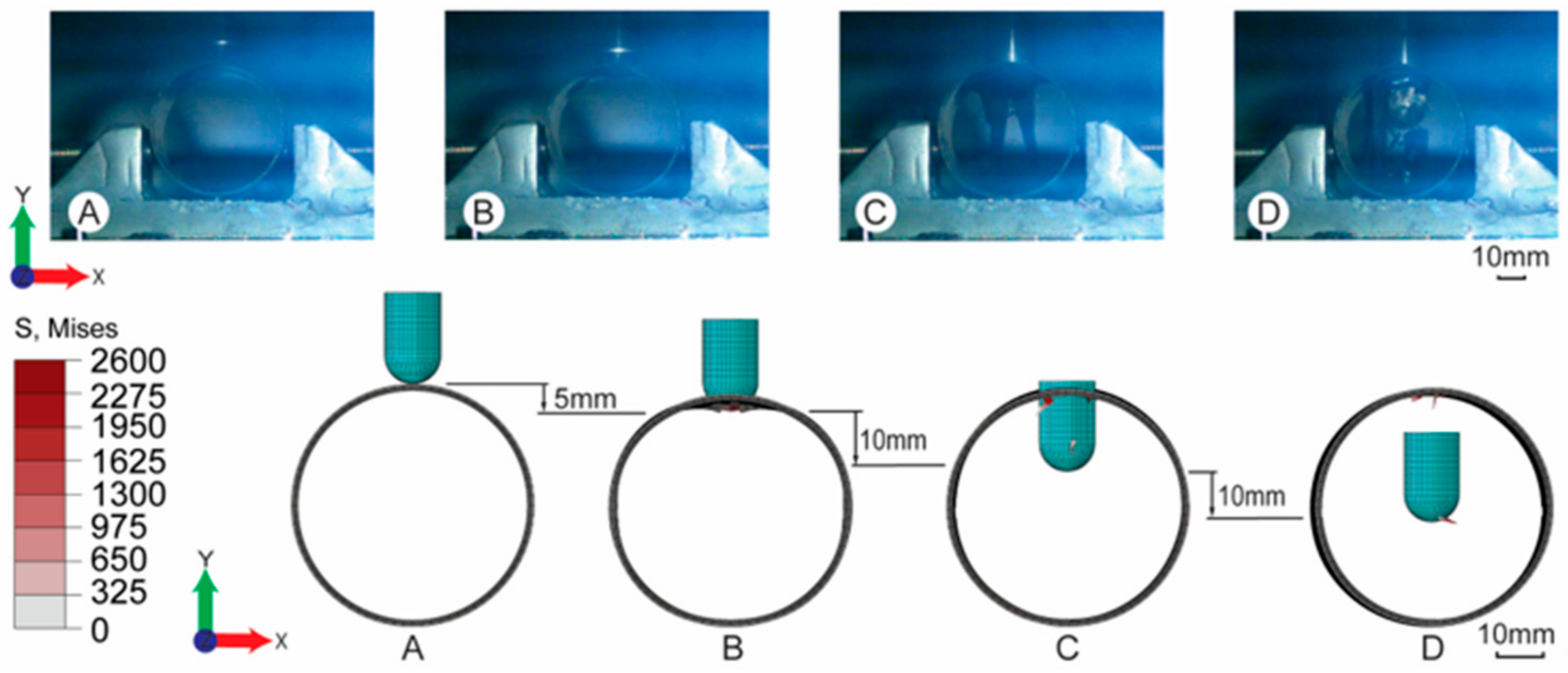
The experiments on FRP composite tubes subjected to low velocity transverse impact at 10 J, 30 J and 50 J were performed, and specific numerical models based on CDM were built taking into account the complex ply sequence of both unidirectional and woven fibre layers. The numerical results agree well with the experimental ones, indicating the effectiveness of the FEM models.
(2)
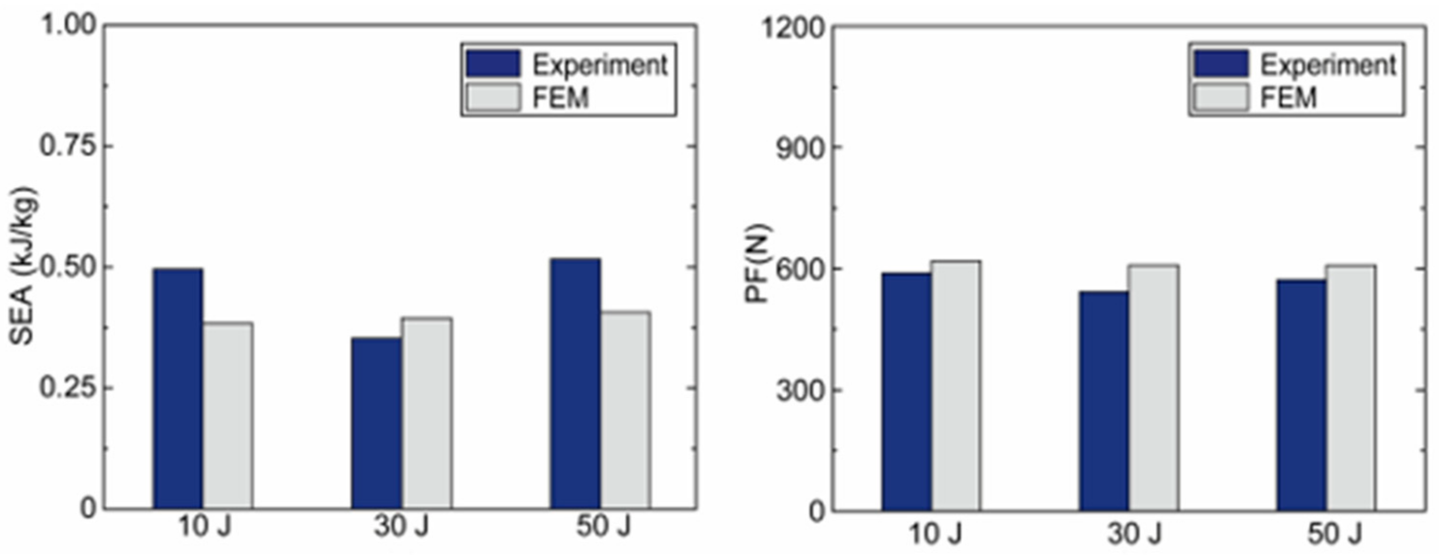
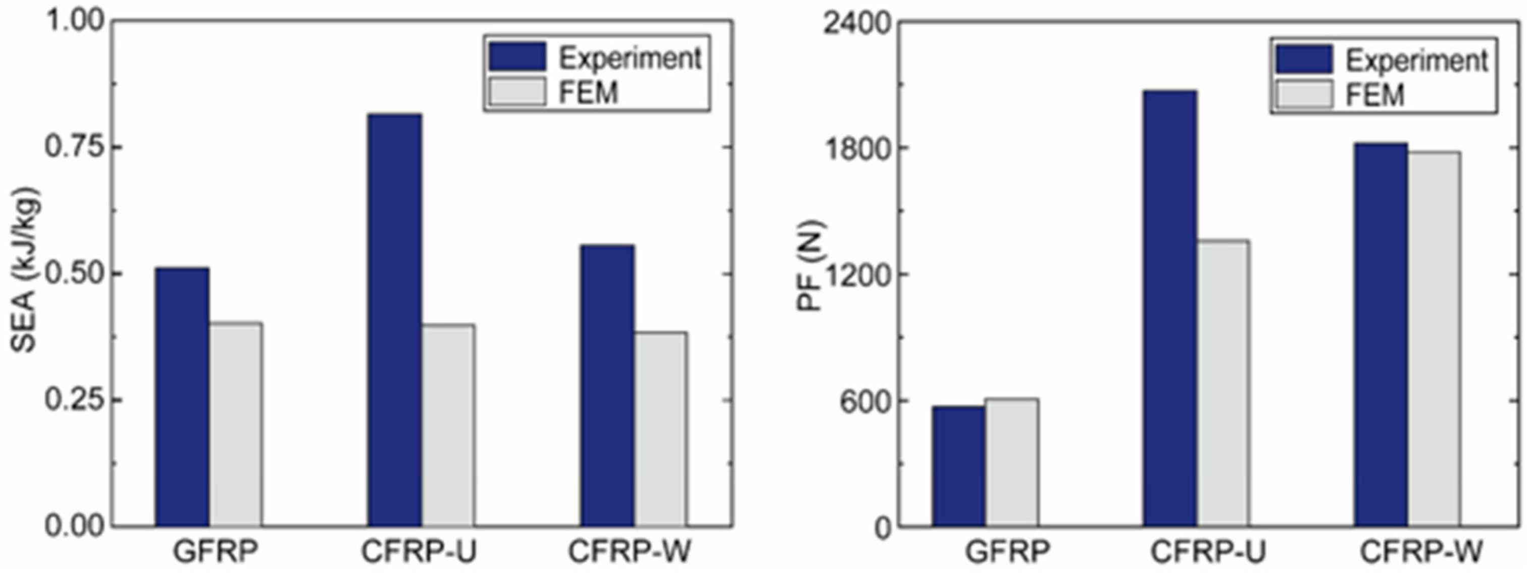
The results show that the initial impact energy does not have a significant effect on the PF and SEA (i.e., the difference in SEA and PF of GFRP tubes under 10 J and 50 J by experiments is only 4% and 3%, respectively). In addition, the effect of material type was investigated. It is found that the PF of GFRP tube is 31% that of the CFRP-U tube, but the SEA value of GFRP is 62% that of CFRP-U, indicating that the GFRP tubes have a potential for excellence in crashworthiness applications.
(3)
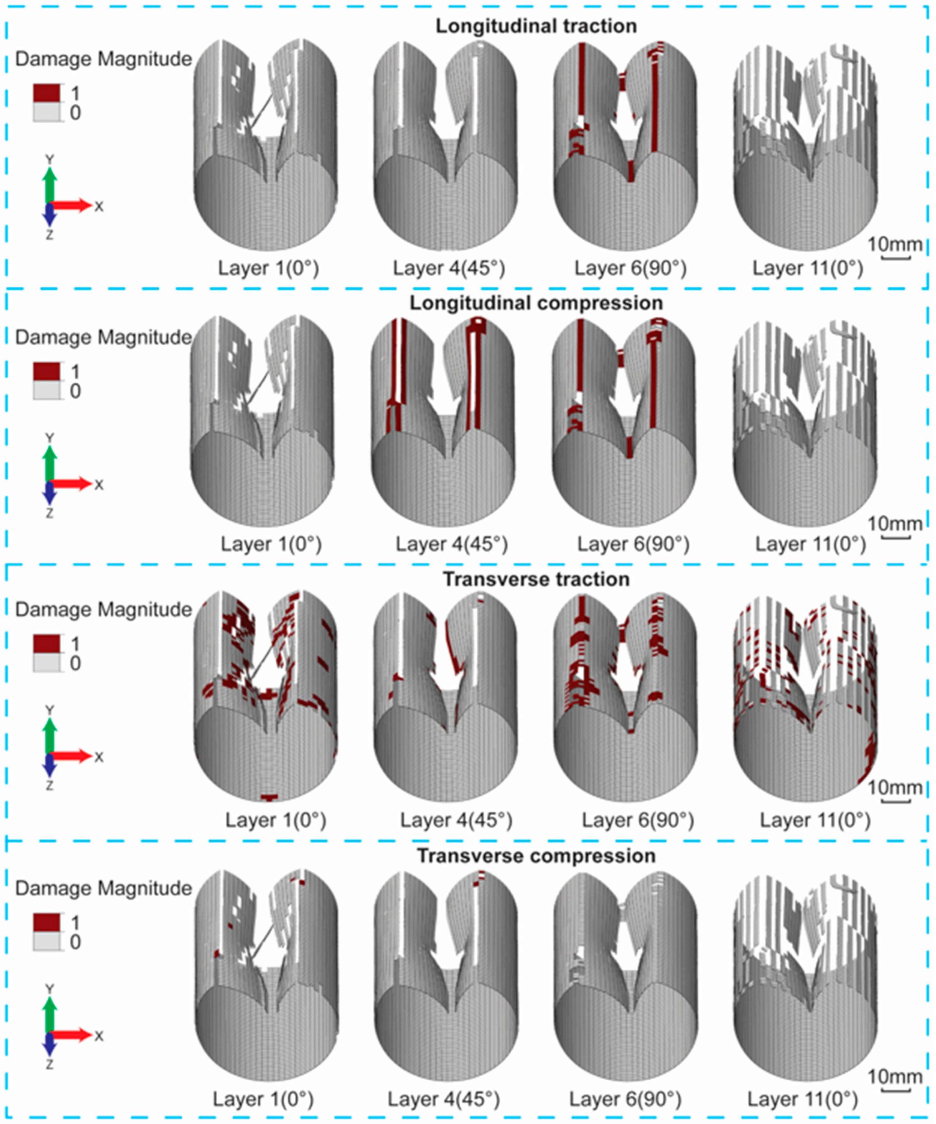
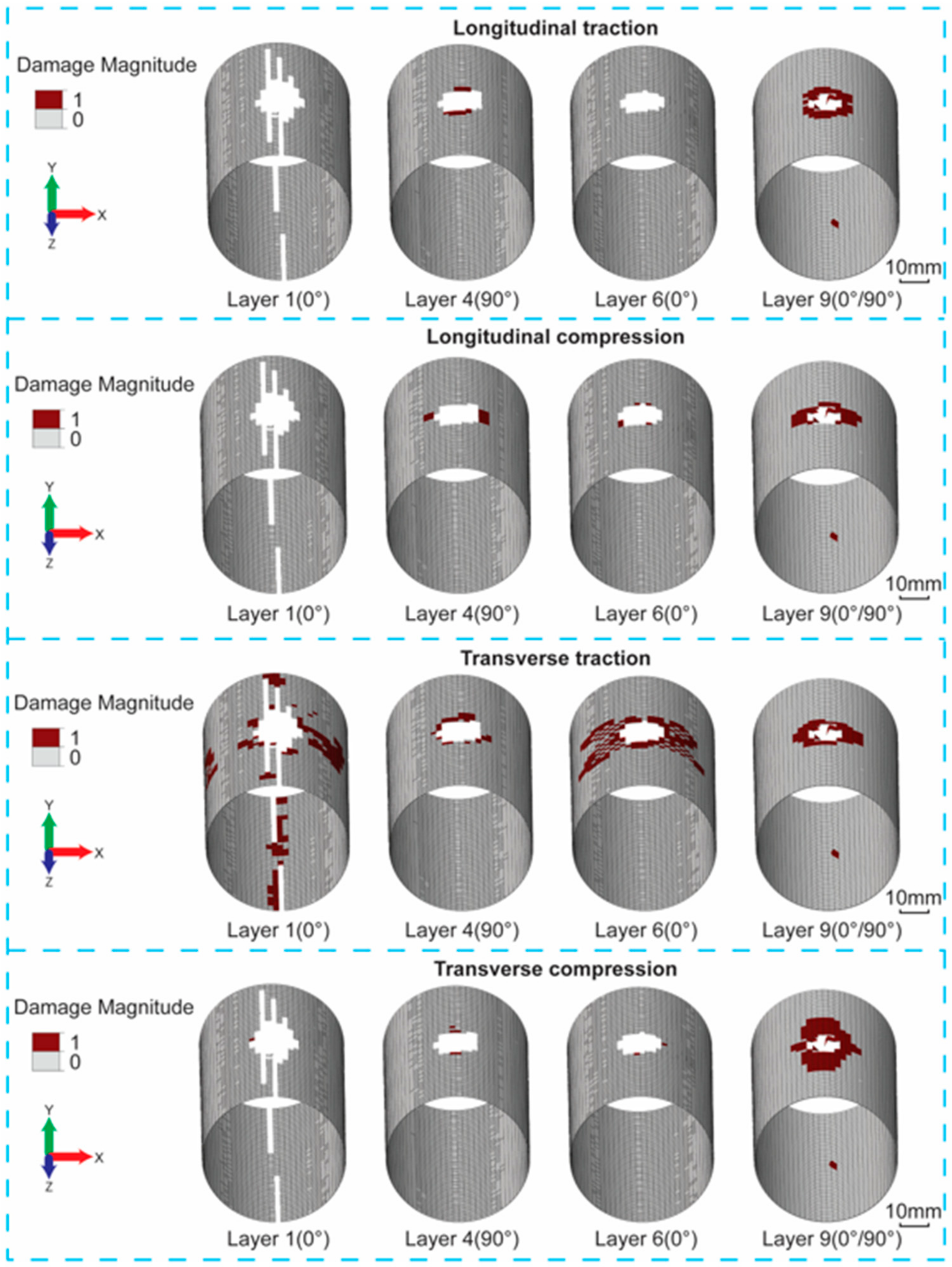
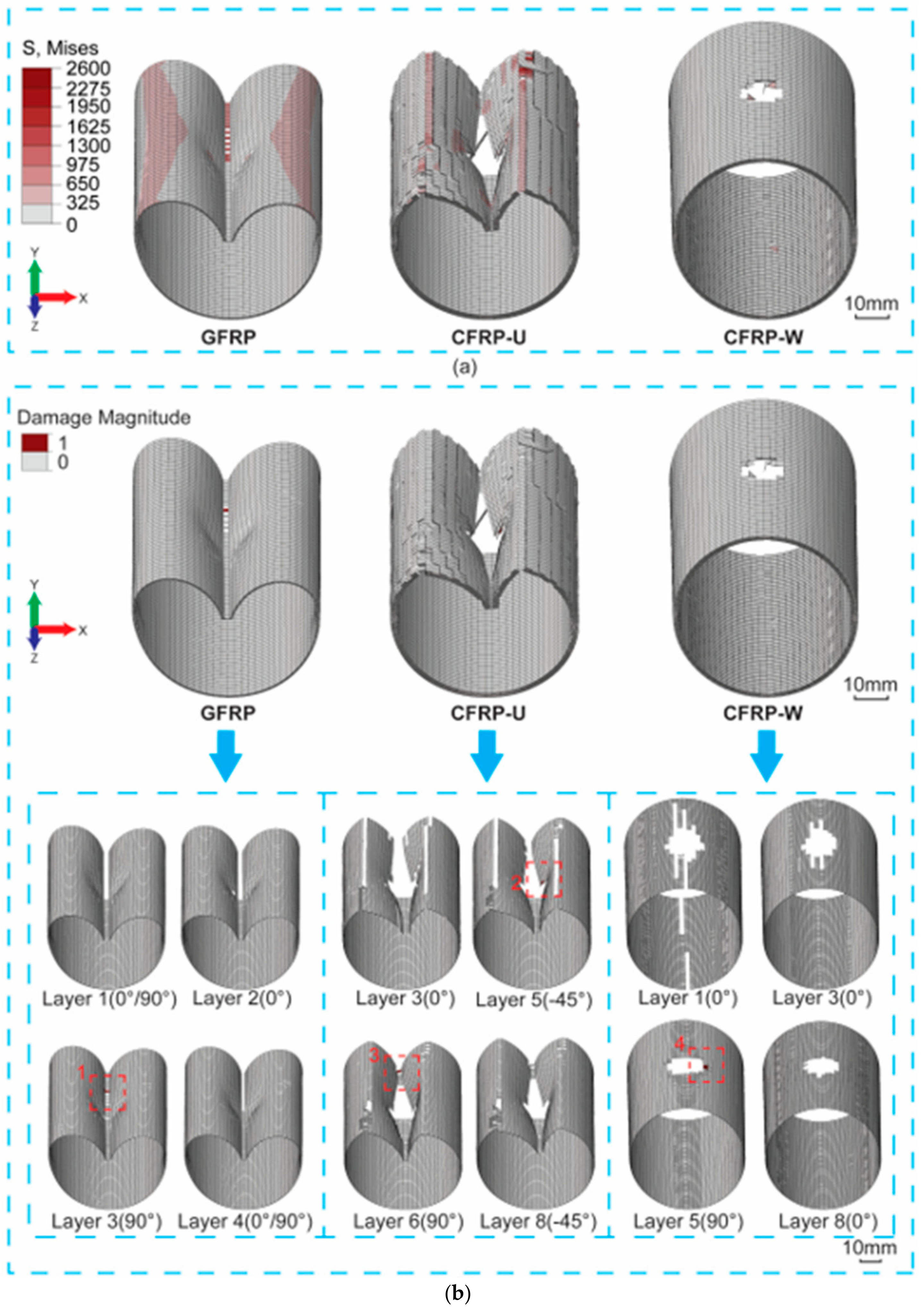
Failure mechanisms of three FRP tubes show that intralaminar damage predominates while interlaminar failure is insignificant. Basically, the failure topographies of the GFRP and CFRP-U tubes are global bending, with significant matrix damage areas, while those of CFRP-W tubes exhibit local penetration with severe fibre and matrix failure.

Author Contributions

Conceptualization, G.W. and Y.C.; methodology, Y.C.; software, G.W. and Y.C.; validation, G.W., K.F. and Y.C.; writing—original draft preparation, G.W.; writing—review and editing, G.W., K.F. and Y.C.; supervision, K.F. and Y.C.; funding acquisition, K.F. and Y.C. All authors have read and agreed to the published version of the manuscript.

Funding

This research was funded by the National Natural Science Foundation of China (12172257), and the Fundamental Research Funds for the Central Universities, China, and Guangdong University Young Innovative Talent Project (2022KQNCX069), and the Scientific Research Start-up Funds (Y01966113, Y01966213) from Southern University of Science and Technology.

Institutional Review Board Statement

Not applicable.

Acknowledgments

The authors acknowledge the National Natural Science Foundation of China (12172257), the Fundamental Research Funds for the Central Universities, China, and Guangdong University Young Innovative Talent Project (2022KQNCX069), and the Scientific Research Start-up Funds (Y01966113, Y01966213) from Southern University of Science and Technology.

Conflicts of Interest

The authors declare no conflict of interest.

Appendix A

In this study, the initial failure criteria and damage evolution have been given in Table A1 [28].
Table A1. Intralaminar failure criteria for FRP composites in the numerical model.
Description Initial Failure CriteriaDamage Evolution
Longitudinal traction φ 1 + = σ ˜ 1 + X 1 + d 1 + = 1 1 r 1 + exp [ 2 g 0 1 + L C G f 1 + g 0 1 + L C ( r 1 + 1 ) ]
Transverse traction φ 2 + = σ ˜ 2 + X 2 + d 2 + = 1 1 r 2 + exp [ 2 g 0 2 + L C G f 2 + g 0 2 + L C ( r 2 + 1 ) ]
Longitudinal compression φ 1 = σ ˜ 1 X 1 d 1 = 1 1 r 1 exp [ 2 g 0 1 L C G f 1 g 0 1 L C ( r 1 1 ) ]
Transverse compression φ 2 = σ ˜ 2 X 2 d 2 = 1 1 r 2 exp [ 2 g 0 2 L C G f 2 g 0 2 L C ( r 2 1 ) ]
Shear φ 12 = σ ˜ 12 X 12 d 12 = min ( α 12 In ( r 12 ) , d 12 max )
* r α (α = 1+, 1−, 2+, 2−) are the tensile and compression damage thresholds along fibre directions 1 and 2, r 12 is the shear damage threshold; those thresholds being abided by Kuhn-Tucker complementary and consistency conditions and defined as 1 initially [28,36]. g 0 α (α = 1+, 1−, 2+, 2−) are the elastic energy densities at the point of damage initiation along fibre directions 1 and 2; L C is the element characteristic length. G f α (α = 1+, 1−, 2+, 2−), are the tensile and compressive fracture energies, X α (α = 1+, 1−, 2+, 2−) are the tensile and compressive strengths along fibre directions 1 or 2, X 12 is shear strength. d α (α = 1+, 1−, 2+, 2−) are the tensile and compressive damage variables along fibre directions 1 (i.e., longitudinal traction and compression) and 2 (i.e., transverse traction and compression), d 12 is the shear damage variable. σ ˜ α (α = 1+, 1−, 2+, 2−) are the effective stresses that can be formulated by:
σ ˜ 1 + = σ 11 1 d 1 + , σ ˜ 1 = σ 11 1 d 1 σ ˜ 2 + = σ 22 1 d 2 + , σ ˜ 2 = σ 22 1 d 2
Then, the tensile and compressive damage variables can be integrated as:
d 1 = d 1 + σ 11 σ 11 + d 1 σ 11 σ 11 d 2 = d 2 + σ 22 σ 22 + d 2 σ 22 σ 22
where d1 and d2 are the damage variables along fibre directions 1 and 2, where they can be introduced in stress–strain constitutive modelling to reflect the material modulus-degradation as follows.
S = 1 ( 1 d 1 ) E 1 ν 12 E 1 0 ν 21 E 2 1 ( 1 d 2 ) E 2 0 0 0 1 ( 1 d 12 ) 2 G 12
where ν 12 and ν 21 are the Poisson ratios, E1 and E2 are the Young’s moduli along the fibre longitudinal and transverse directions, respectively, and G12 is shear modulus.

References

  1. Jena, T.; Kaewunruen, S. Life cycle sustainability assessments of an innovative FRP composite footbridge. Sustainability 2021, 13, 13000. [Google Scholar] [CrossRef]
  2. Kumar, A.P.; Sezhian, M.V. Lateral Crashworthiness Performance of a Novel Hybrid Composite Bi-Tubular structures—An Experimental Study. In Recent Advances in Materials Technologies; Springer: Singapore, 2023; pp. 407–414. [Google Scholar]
  3. Hussain, N.N.; Regalla, S.P.; Rao, Y.V.D. Study on influence of notch triggers on absorption of energy for composite automobile crash box under impact loads. Mater. Today Proc. 2021, 38, 3220–3231. [Google Scholar] [CrossRef]
  4. Bell, M.; Fick, D.; Ament, R.; Lister, N.-M. The Use of Fiber-Reinforced Polymers in Wildlife Crossing Infrastructure. Sustainability 2020, 12, 1557. [Google Scholar] [CrossRef] [Green Version]
  5. Gemi, D.S.; Şahin, Ö.S.; Gemi, L. Experimental investigation of axial compression behavior after low velocity impact of glass fiber reinforced filament wound pipes with different diameter. Compos. Structures 2022, 280, 114929. [Google Scholar] [CrossRef]
  6. Bai, C.; Ma, Q.; Gan, X.; Zhou, T. Theoretical prediction model of mean crushing force of CFRP-Al hybrid circular tubes under axial compression. Polym. Compos. 2021, 42, 5035–5050. [Google Scholar] [CrossRef]
  7. Zhou, J.-K.; Lin, W.-K.; Guo, S.-X.; Zeng, J.-J.; Bai, Y.-L. Behavior of FRP-confined FRP spiral reinforced concrete square columns (FCFRCs) under axial compression. J. Build. Eng. 2022, 45, 103452. [Google Scholar] [CrossRef]
  8. Guo, Y.; Chen, L.; Zhu, C.; Liu, H.; Pan, X.; Du, B.; Zhao, W.; Li, W. Fabrication and axial compression test of thermoplastic composite cylindrical sandwich structures with hierarchical honeycomb core. Compos. Struct. 2021, 275, 114453. [Google Scholar] [CrossRef]
  9. Li, S.; Chan, T.-M.; Young, B. Experimental investigation on axial compressive behavior of novel FRP-ECC-HSC composite short column. Compos. Struct. 2023, 303, 116285. [Google Scholar] [CrossRef]
  10. Li, Y.-F.; Hsu, T.-H.; Hsieh, F.-C. A study on improving the mechanical behaviors of the pultruded GFRP composite material members. Sustainability 2019, 11, 577. [Google Scholar] [CrossRef] [Green Version]
  11. Valizadeh, A.; Aslani, F. Life-Cycle Assessment of Fibre-Reinforced Polymers Dwellings Compared to Traditional Structures. Sustainability 2022, 14, 11887. [Google Scholar] [CrossRef]
  12. Shang, X.-Y.; Yu, J.-T.; Li, L.-Z.; Lu, Z.-D. Strengthening of RC Structures by Using Engineered Cementitious Composites: A Review. Sustainability 2019, 11, 3384. [Google Scholar] [CrossRef] [Green Version]
  13. Vashisth, A.; Bakis, C.E.; Ruggeri, C.R.; Henry, T.C.; Roberts, G.D. Ballistic impact response of carbon/epoxy tubes with variable nanosilica content. J. Compos. Mater. 2018, 52, 1589–1604. [Google Scholar] [CrossRef]
  14. Zhou, H.; Li, C.; Zhang, L.; Crawford, B.; Milani, A.S.; Ko, F.K. Micro-XCT analysis of damage mechanisms in 3D circular braided composite tubes under transverse impact. Compos. Sci. Technol. 2018, 155, 91–99. [Google Scholar] [CrossRef]
  15. Cormier, J.-R.; LaPlante, G. Study of the effects of low-velocity impact on a composite bicycle down tube. Compos. Struct. 2018, 198, 144–155. [Google Scholar] [CrossRef]
  16. Mokhtar, I.; Yahya, M.Y.; Hassan, S.A.; Santulli, C. Transverse impact response of filament wound basalt composite tubes. Compos. Part B Eng. 2017, 128, 134–145. [Google Scholar] [CrossRef]
  17. Wu, Z.; Shi, L.; Cheng, X.; Xiang, Z.; Hu, X. Transverse impact behavior and residual axial compression characteristics of braided composite tubes: Experimental and numerical study. Int. J. Impact Eng. 2020, 142, 103578. [Google Scholar] [CrossRef]
  18. Deniz, M.E.; Karakuzu, R.; Sari, M.; Icten, B.M. On the residual compressive strength of the glass–epoxy tubes subjected to transverse impact loading. J. Compos. Mater. 2012, 46, 737–745. [Google Scholar] [CrossRef]
  19. Li, S.; Guo, X.; Li, Q.; Ruan, D.; Sun, G. On lateral compression of circular aluminum, CFRP and GFRP tubes. Compos. Struct. 2020, 232, 111534. [Google Scholar] [CrossRef]
  20. Sun, G.; Guo, X.; Li, S.; Ruan, D.; Li, Q. Comparative study on aluminum/GFRP/CFRP tubes for oblique lateral crushing. Thin-Walled Struct. 2020, 152, 106420. [Google Scholar] [CrossRef]
  21. Liu, Y.; Zhuang, W.; Wu, D. Performance and damage of carbon fibre reinforced polymer tubes under low-velocity transverse impact. Thin-Walled Struct. 2020, 151, 106727. [Google Scholar] [CrossRef]
  22. Zhang, C.; Tan, K.T. Low-velocity impact response and compression after impact behavior of tubular composite sandwich structures. Compos. Part B Eng. 2020, 193, 108026. [Google Scholar] [CrossRef]
  23. Reyes, P.; Reviriego, P.; Maestro, J.; Ruano, O. New protection techniques against SEUs for moving average filters in a radiation environment. IEEE Trans. Nucl. Sci. 2007, 54, 957–964. [Google Scholar] [CrossRef]
  24. Chen, Y.; Ye, L.; Fu, K. Progressive failure of CFRP tubes reinforced with composite sandwich panels: Numerical analysis and energy absorption. Compos. Struct. 2021, 263, 113674. [Google Scholar] [CrossRef]
  25. Chen, Y.; Hou, S.; Fu, K.; Han, X.; Ye, L. Low-velocity impact response of composite sandwich structures: Modelling and experiment. Compos. Struct. 2017, 168, 322–334. [Google Scholar] [CrossRef]
  26. Dassault Systèmes Simulia. Abaqus Analysis User’s Manual, Abaqus 6.11; Dassault Systèmes Simulia: Vélizy-Villacoublay, France, 2012. [Google Scholar]
  27. Bui, Q. A modified Benzeggagh-Kenane fracture criterion for mixed-mode delamination. J. Compos. Mater. 2011, 45, 389–413. [Google Scholar] [CrossRef]
  28. Johnson, A.F. Modelling fabric reinforced composites under impact loads. Compos. Part A Appl. Sci. Manuf. 2001, 32, 1197–1206. [Google Scholar] [CrossRef]
  29. Soden, P.D.; Hinton, M.J.; Kaddour, A. Lamina Properties, Lay-up Configurations and Loading Conditions for a Range of Fibre reinforced Composite Laminates. In Failure Criteria in Fibre-Reinforced-Polymer Composites; Elsevier: Amsterdam, The Netherlands, 2004; pp. 30–51. [Google Scholar]
  30. Mitsubishi Chemical Carbon Fiber and Composites, Inc. Newport 301 Product Data Sheet; Newport Adhesive and Composites, Inc.: Irvine, CA, USA, 2016. [Google Scholar]
  31. Kirk, J.; Munro, M.; Beaumont, P. The fracture energy of hybrid carbon and glass fibre composites. J. Mater. Sci. 1978, 13, 2197–2204. [Google Scholar] [CrossRef]
  32. Pham, D.C.; Narayanaswamy, S. An Optimization Tool for Impact Analysis of Composite Structures. Procedia Eng. 2014, 75, 3–8. [Google Scholar] [CrossRef] [Green Version]
  33. Phadnis, V.; Pandya, K.; Naik, N.; Roy, A.; Silberschmidt, V. Ballistic impact behaviour of woven fabric composite: Finite element analysis and experiments. In Journal of Physics: Conference Series; IOP Publishing: Bristol, UK, 2013; p. 012019. [Google Scholar]
  34. Chen, Y.; Ye, L.; Escobedo-Diaz, J.P.; Zhang, Y.X.; Fu, K.K. Quasi-static and dynamic progressive crushing of CF/EP composite sandwich panels under in-plane localised compressive loads. Compos. Struct. 2019, 222, 110893. [Google Scholar] [CrossRef]
  35. Chen, Y.; Ye, L.; Escobedo-Diaz, J.P.; Zhang, Y. Effect of initiator geometry on energy absorption of CFRP tubes under dynamic crushing. Int. J. Crashworthiness 2021, 26, 526–536. [Google Scholar] [CrossRef]
  36. Sokolinsky, V.S.; Indermuehle, K.C.; Hurtado, J.A. Numerical simulation of the crushing process of a corrugated composite plate. Compos. Part A Appl. Sci. Manuf. 2011, 42, 1119–1126. [Google Scholar] [CrossRef]
Figure 1. Illustration of GFRP, CFRP-U and CFRP-W tubes with their corresponding ply sequences.
Sustainability 15 00056 g001
Figure 2. (a) Experimental scenarios, and (b) FEM set-up.
Sustainability 15 00056 g002
Figure 3. Force–displacement curves of GFRP composite tubes when subjected to different impact energies of (a) 10 J (b) 30 J and (c) 50 J.
Sustainability 15 00056 g003
Figure 4. SEA and PF of GFRP at three magnitudes of impact energies (10 J, 30 J, 50 J).
Sustainability 15 00056 g004
Figure 5. Failure morphologies of GFRP composite tubes by both experiments and FEM during transverse impact at 50 J (A, B, C and D denote the impact displacement at 0, 5, 15 and 25 mm, respectively).
Sustainability 15 00056 g005
Figure 6. Failure mechanisms of the GFRP tube at Point D.
Sustainability 15 00056 g006
Figure 7. Force–displacement curves of (a) GFRP (b) CFRP-U and (c) CFRP-W composite tubes when subjected to transverse impact with an initial energy of 50 J.
Sustainability 15 00056 g007
Figure 8. SEA and PF of GFRP, CFRP-U and CFRP-W composite tubes when subjected to transverse impact with an initial energy of 50 J.
Sustainability 15 00056 g008
Figure 9. Failure morphologies of CFRP-U composite tubes by both experiments and FEM during transverse impact at 50 J (A, B, C and D denote the impact displacement at 0, 5, 15 and 25 mm, respectively).
Sustainability 15 00056 g009
Figure 10. Failure mechanisms of CFRP-U tube at Point D.
Sustainability 15 00056 g010
Figure 11. Failure morphologies of CFRP-W composite tubes by both experiments and FEM during transverse impact at 50 J (A, B, C and D denote the impact displacement at 0, 5, 15 and 25 mm, respectively).
Sustainability 15 00056 g011
Figure 12. Failure mechanisms of CFRP-W tube at Point D.
Sustainability 15 00056 g012
Figure 13. (a) Von Mises stresses and (b) interlaminar damage and deformation behaviours of GFRP, CFRP-U and CFRP-W composite tubes at Point D.
Sustainability 15 00056 g013
Table 1. Impact energies and velocities in the experiments.
Impact Velocity (m/s)Impact Energy (J)
1.9010
3.2930
4.2550
Table 2. Material parameters of GFRP composites [20,29,31,32,33].
DescriptionUnidirectionalWoven
Density (kg/m3)18001800
Longitudinal Young’s modulus (GPa)49.625.8
Transverse Young’s modulus (GPa)1723.9
Principal Poisson’s ratio0.2780.118
Shear modulus (MPa)28004500
Longitudinal tensile strength (MPa)1230479.8
Transverse tensile strength (MPa)40423.6
Longitudinal compressive strength (MPa)1610445.7
Transverse compressive strength (MPa)145358.8
In-plane shear strength (MPa)9265.6
Longitudinal traction fracture energy (KJ/m2)35040
Longitudinal compression fracture energy (KJ/m2)35060
Transverse traction fracture energy (KJ/m2)0.520
Transverse compression fracture energy (KJ/m2)1.5750
Interlaminar normal strength (MPa)3535
Interlaminar shear strength (MPa)6565
Mode I fracture toughness (KJ/m2)0.50.5
Mode II fracture toughness (KJ/m2)1.61.6
Disclaimer/Publisher’s Note: The statements, opinions and data contained in all publications are solely those of the individual author(s) and contributor(s) and not of MDPI and/or the editor(s). MDPI and/or the editor(s) disclaim responsibility for any injury to people or property resulting from any ideas, methods, instructions or products referred to in the content.

