
Towards Global Cleaner Energy and Hydrogen Production: A Review and Application ORC Integrality with Multigeneration Systems

 ,
,  ,
,  , , ,
, , ,
Abstract
:1. Introduction
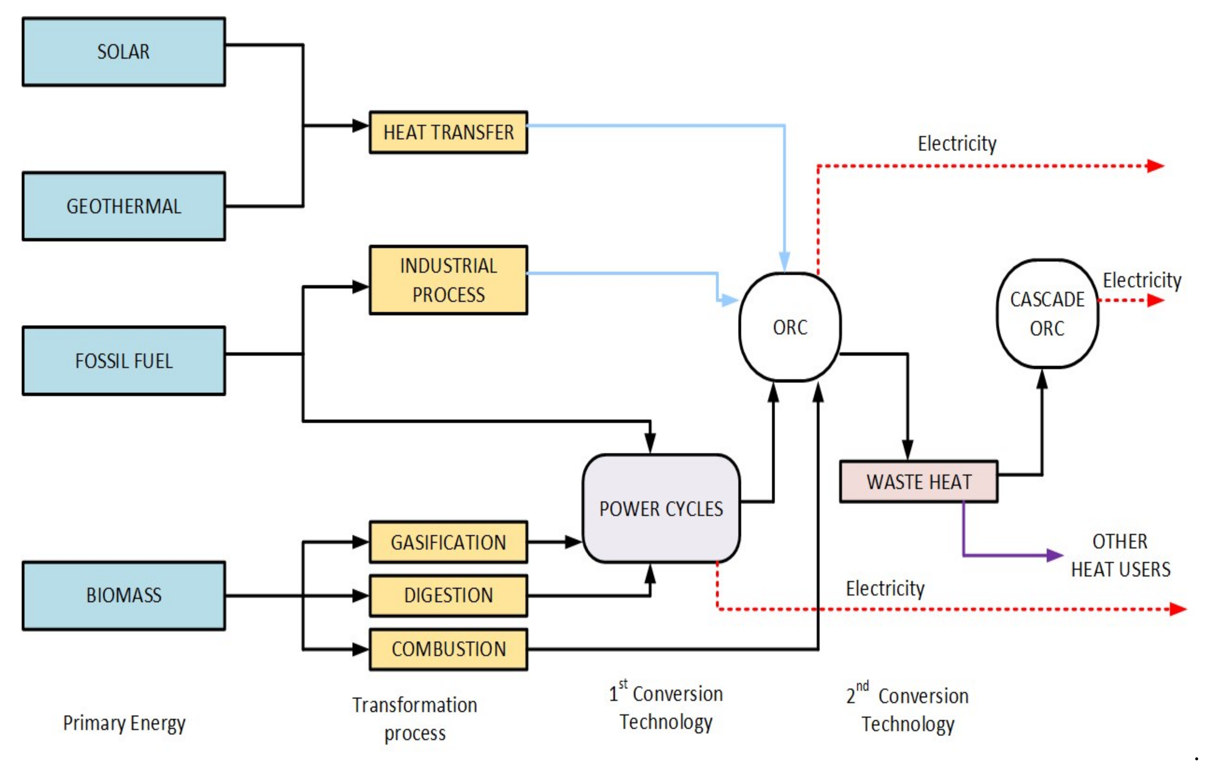
2. Organic Rankine Cycle (ORC)
2.1. ORC Applications
2.1.1. Biomass Combined Heat and Power (CHP)
2.1.2. Solar Power Cycles
2.1.3. Geothermal Binary Power Cycles
2.1.4. Waste Heat Recovery from Internal Combustion Engines (ICE)
2.1.5. Exhaust Heat Recovery in Gas and Steam Power Cycles
2.1.6. ORC for Ocean Thermal Energy Conversion (OTEC)
3. ORC Integration with Multigeneration Systems
- -
- Indexing: All the articles selected are indexed in Scopus and Web of Science.
- -
- Relevance: Articles that used the thermodynamics approach to evaluate multigeneration systems were the only ones considered.
- -
- Publication time: Only articles published after the year 2015 were considered for the review.
4. System Description
5. Mathematical Modeling
- The Air Mass 1.5 direct spectra ASTM (AM1.5D) is used as the reference of the solar light spectrum.
- The dead-state properties used as the reference for temperature and pressure are 101.3 kPa and 298 K, respectively.
- DC/AC conversion efficiency of the CPVT inverter is 0.98, whereas the solar field capacity factor is defined as 0.33.
- The heat exchangers within the multigeneration system are considered isobaric.
- The ORC pump and turbine efficiencies are 0.85 and 0.80, respectively.
- For this system, changes in kinetic and potential energy are also considered insignificant.
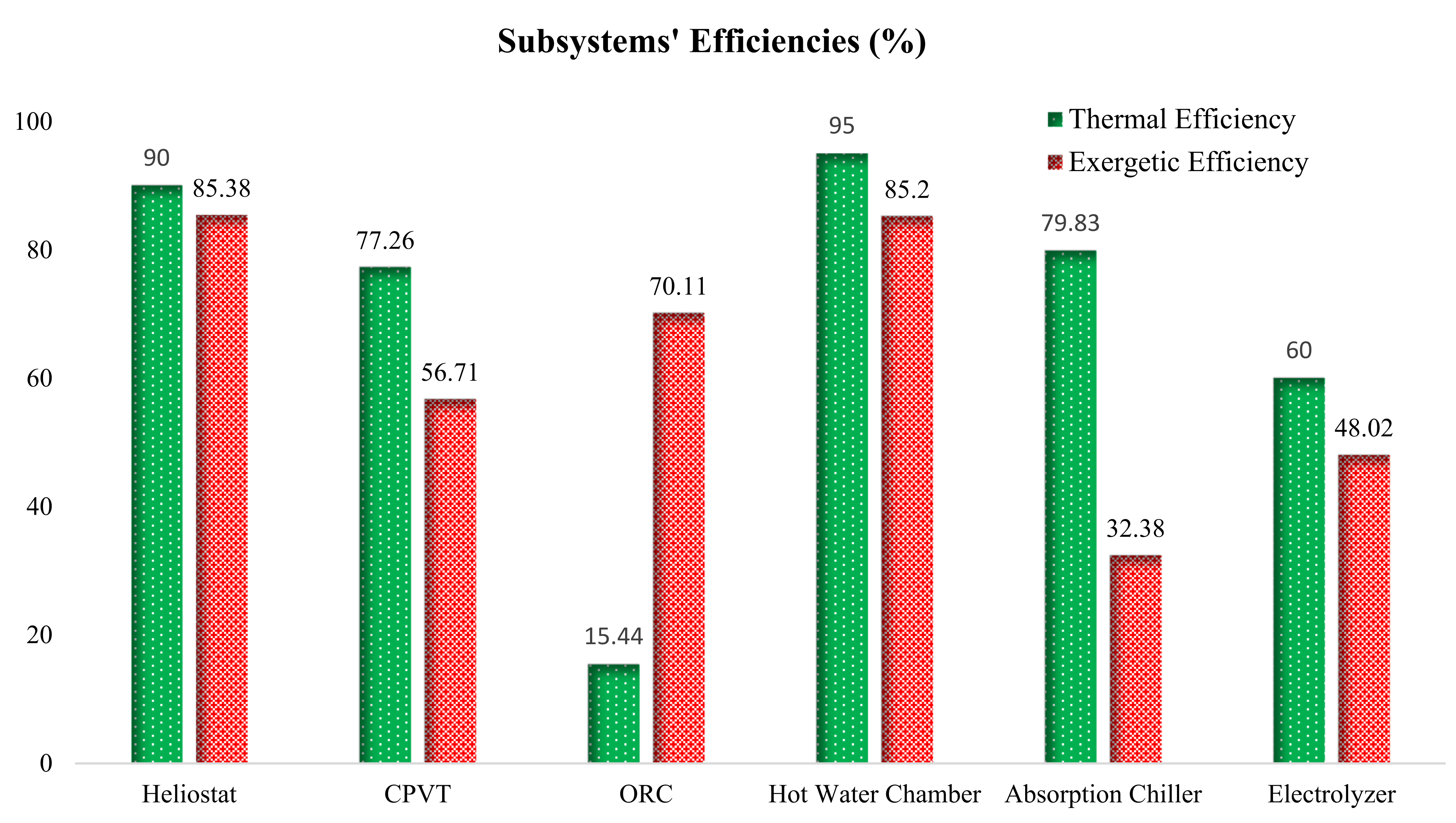
Thermodynamic Analysis
6. Results and Discussions
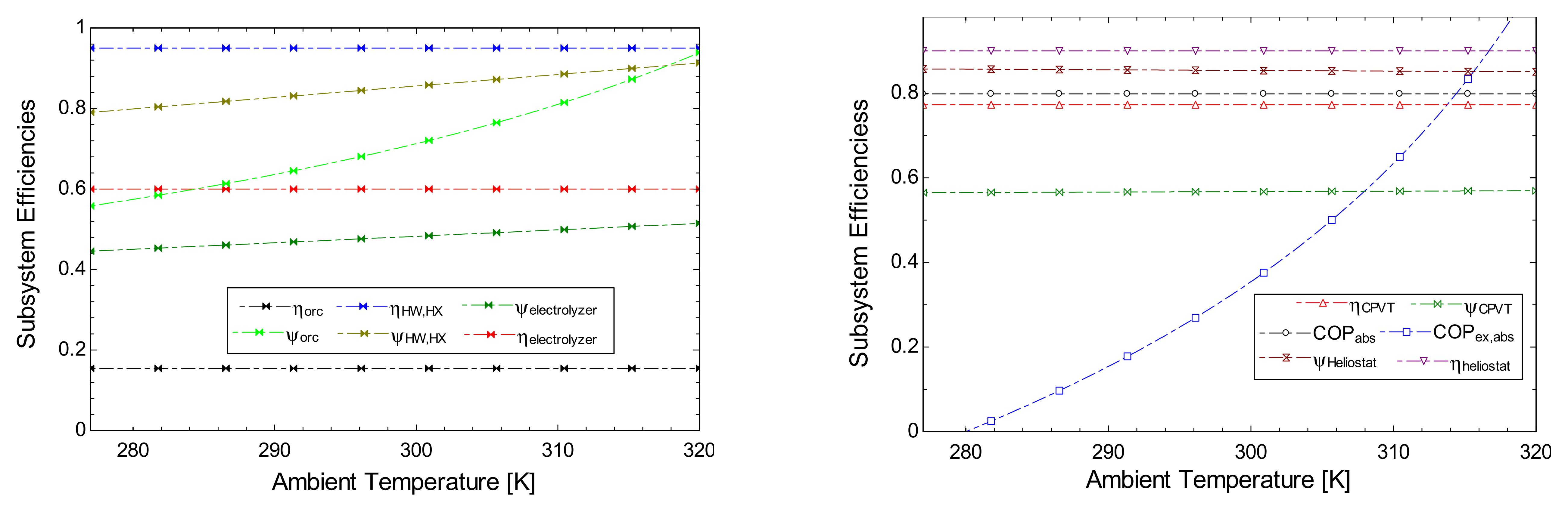
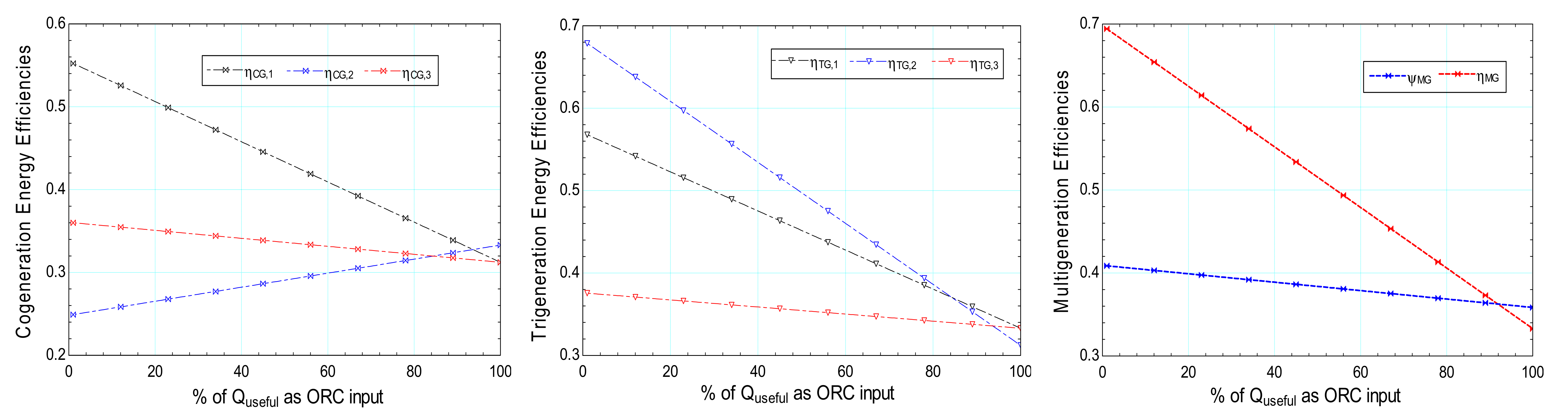
Parametric Analysis Results
7. Conclusions
- Based on the reviewed works of literature, solar energy is the most predominant renewable energy source for ORC integrated systems, but biomass and geothermal energy sources are also commonly used.
- The integration of hydrogen production is an integral part of most ORC-based multigeneration systems, as the production of hydrogen further helps maximize the renewable energy input in practical applications.
- The integration of ORC with multigeneration was advantageous, as it increased the electricity production by 16% (with the addition of 62.28 kW to the CPVT electricity production).
- The multigeneration system also achieved competitive thermal and exergetic efficiencies (47.9% and 37.88%, respectively) when compared with existing works of literature.
- The sensitivity of the system to changes in ambient temperature further shows the precedence of the multigeneration system modeled in this study, as the energy efficiency was stable under varying dead-state temperatures.
- This system will also contribute to the mitigation of carbon, as it reduces a sizable quantity of greenhouse gases.
Author Contributions
Funding
Institutional Review Board Statement
Informed Consent Statement
Data Availability Statement
Acknowledgments
Conflicts of Interest
References
- Adun, H.; Wole-Osho, I.; Okonkwo, E.C.; Kavaz, D.; Dagbasi, M. A Critical Review of Specific Heat Capacity of Hybrid Nanofluids for Thermal Energy Applications. J. Mol. Liq. 2021, 40, 116890. [Google Scholar] [CrossRef]
- Mert, İ.; Bilgic, H.H.; Yağlı, H.; Koç, Y. Deep Neural Network Approach to Estimation of Power Production for an Organic Rankine Cycle System. J. Braz. Soc. Mech. Sci. Eng. 2020, 42, 620. [Google Scholar] [CrossRef]
- Kumar, A.; Rakshit, D. A Critical Review on Waste Heat Recovery Utilization with Special Focus on Organic Rankine Cycle Applications. Clean. Eng. Technol. 2021, 5, 100292. [Google Scholar] [CrossRef]
- Dale, S. BP Energy Outlook; BP: London, UK, 2020. [Google Scholar]
- Naderi, S.; Torabi, F. Numerical Investigation of Wake behind a HAWT Using Modified Actuator Disc Method. Energy Convers. Manag. 2017, 148, 1346–1357. [Google Scholar] [CrossRef]
- Li, L.; Lin, J.; Wu, N.; Xie, S.; Meng, C.; Zheng, Y.; Wang, X.; Zhao, Y. Review and Outlook on the International Renewable Energy Development. Energy Built Environ. 2021, 3, 139–157. [Google Scholar] [CrossRef]
- Okonkwo, E.C.; Wole-Osho, I.; Kavaz, D.; Abid, M.; Al-Ansari, T. Thermodynamic Evaluation and Optimization of a Flat Plate Collector Operating with Alumina and Iron Mono and Hybrid Nanofluids. Sustain. Energy Technol. Assess. 2020, 37, 100636. [Google Scholar] [CrossRef]
- Kim, C. A Review of the Deployment Programs, Impact, and Barriers of Renewable Energy Policies in Korea. Renew. Sustain. Energy Rev. 2021, 144, 110870. [Google Scholar] [CrossRef]
- Kwon, S. Ensuring Renewable Energy Utilization with Quality of Service Guarantee for Energy-Efficient Data Center Operations. Appl. Energy 2020, 276, 115424. [Google Scholar] [CrossRef]
- IRENA. Global Renewables Outlook: Energy Transformation 2050; International Renewable Energy Agency: Abu Dhabi, United Arab Emirates, 2020; ISBN 9789292602383.
- Adun, H.; Kavaz, D.; Dagbasi, M. Review of Ternary Hybrid Nanofluid: Synthesis, Stability, Thermophysical Properties, Heat Transfer Applications, and Environmental Effects. J. Clean. Prod. 2021, 328, 129525. [Google Scholar] [CrossRef]
- Bamisile, O.; Li, J.; Huang, Q.; Obiora, S.; Ayambire, P.; Zhang, Z.; Hu, W. Environmental Impact of Hydrogen Production from Southwest China’s Hydro Power Water Abandonment Control. Int. J. Hydrog. Energy 2020, 45, 25587–25598. [Google Scholar] [CrossRef]
- Atikol, U.; Abid, M.; Adebayo, V.O. Energetic and Exegetic Analysis of a Novel Multi-Generation System Using Solar Power Tower. Int. J. Exergy 2019, 29, 211. [Google Scholar] [CrossRef]
- Ghasemiasl, R.; Khalili Abhari, M.; Javadi, M.A.; Ghomashi, H. 4E Investigating of a Combined Power Plant and Converting It to a Multigeneration System to Reduce Environmental Pollutant Production and Sustainable Development. Energy Convers. Manag. 2021, 245, 114468. [Google Scholar] [CrossRef]
- Bamisile, O.; Jing, H.; Adedeji, M.; Li, J.; Anane, P.O.K.; Dagbasi, M.; Huang, Q. Towards Cleaner/Sustainable Energy Consumption in Agriculture Farms: Performance Assessment of Two Innovative High-Performance Solar-Based Multigeneration Systems. Energy Convers. Manag. 2021, 244, 114507. [Google Scholar] [CrossRef]
- Azariyan, H.; Vajdi, M.; Takleh, H.R. Assessment of a High-Performance Geothermal-Based Multigeneration System for Production of Power, Cooling, and Hydrogen: Thermodynamic and Exergoeconomic Evaluation. Energy Convers. Manag. 2021, 236, 113970. [Google Scholar] [CrossRef]
- Tariq, S.; Safder, U.; Nguyen, H.T.; Ifaei, P.; Heo, S.K.; Yoo, C.K. A Novel Solar Assisted Multigeneration System Devoid of External Utilities for Drought Adaptation Considering Water-Exergy Nexus Analysis. Appl. Therm. Eng. 2021, 198, 117500. [Google Scholar] [CrossRef]
- Hung, T.C.; Shai, T.Y.; Wang, S.K. A Review of Organic Rankine Cycles (ORCs) for the Recovery of Low-Grade Waste Heat. Energy 1997, 22, 661–667. [Google Scholar] [CrossRef]
- Fallis, A. Waste Heat Recovery:—Technology and Opportunities in U.S. Industry. J. Chem. Inf. Model. 2013, 53, 1689–1699. [Google Scholar]
- Quoilin, S.; Van Den Broek, M.; Declaye, S.; Dewallef, P.; Lemort, V. Techno-Economic Survey of Organic Rankine Cycle (ORC) Systems. Renew. Sustain. Energy Rev. 2013, 22, 168–186. [Google Scholar] [CrossRef] [Green Version]
- Cai, D.; Bamisile, O.; Adebayo, V.; Huang, Q.; Dagbasi, M.; Okonkwo, E.C.; Al-Ansari, T. Integration of Wind Turbine with Heliostat Based CSP/CPVT System for Hydrogen Production and Polygeneration: A Thermodynamic Comparison. Int. J. Hydrog. Energy 2020, 47, 3316–3345. [Google Scholar] [CrossRef]
- Jouhara, H.; Żabnieńska-Góra, A.; Khordehgah, N.; Doraghi, Q.; Ahmad, L.; Norman, L.; Axcell, B.; Wrobel, L.; Dai, S. Thermoelectric Generator (TEG) Technologies and Applications. Int. J. Thermofluids 2021, 9, 100063. [Google Scholar] [CrossRef]
- Gao, W.; Wu, Z.; Tian, Z.; Zhang, Y. Experimental Investigation on an R290-Based Organic Rankine Cycle Utilizing Cold Energy of Liquid Nitrogen. Appl. Therm. Eng. 2021, 202, 117757. [Google Scholar] [CrossRef]
- Wu, Z.; Chen, L.; Feng, H.; Ge, Y. Constructal Thermodynamic Optimization for a Novel Kalina-Organic Rankine Combined Cycle to Utilize Waste Heat. Energy Rep. 2021, 7, 6095–6106. [Google Scholar] [CrossRef]
- Yağlı, H.; Koç, Y.; Köse, Ö.; Koç, A.; Yumrutaş, R. Optimisation of Simple and Regenerative Organic Rankine Cycles Using Jacket Water of an Internal Combustion Engine Fuelled with Biogas Produced from Agricultural Waste. Process. Saf. Environ. Prot. 2021, 155, 17–31. [Google Scholar] [CrossRef]
- Angrisani, G.; Roselli, C.; Sasso, M. Distributed Microtrigeneration Systems. Prog. Energy Combust. Sci. 2012, 38, 502–521. [Google Scholar] [CrossRef]
- Al-Attab, K.A.; Zainal, Z.A. Externally Fired Gas Turbine Technology: A Review. Appl. Energy 2015, 138, 474–487. [Google Scholar] [CrossRef]
- Jana, K.; De, S. Sustainable Polygeneration Design and Assessment through Combined Thermodynamic, Economic and Environmental Analysis. Energy 2015, 91, 540–555. [Google Scholar] [CrossRef]
- Rahman, M.; Malmquist, A. Modeling and Simulation of an Externally Fired Micro-Gas Turbine for Standalone Polygeneration Application. J. Eng. Gas Turbines Power 2016, 138, 112301. [Google Scholar] [CrossRef]
- Maraver, D.; Uche, J.; Royo, J. Assessment of High Temperature Organic Rankine Cycle Engine for Polygeneration with MED Desalination: A Preliminary Approach. Energy Convers. Manag. 2012, 53, 108–117. [Google Scholar] [CrossRef]
- Vélez, F.; Segovia, J.J.; Martín, M.C.; Antolín, G.; Chejne, F.; Quijano, A. A Technical, Economical and Market Review of Organic Rankine Cycles for the Conversion of Low-Grade Heat for Power Generation. Renew. Sustain. Energy Rev. 2012, 16, 4175–4189. [Google Scholar] [CrossRef]
- Agency, I.E. IEA Key World Energy Statistics—2008 Edition; IEA: Paris, France, 2008. [Google Scholar]
- Tchanche, B.F.; Lambrinos, G.; Frangoudakis, A.; Papadakis, G. Low-Grade Heat Conversion into Power Using Organic Rankine Cycles—A Review of Various Applications. Renew. Sustain. Energy Rev. 2011, 15, 3963–3979. [Google Scholar] [CrossRef]
- Lewis, N.S.; Nocera, D.G. Powering the Planet: Chemical Challenges in Solar Energy Utilization. Proc. Natl. Acad. Sci. USA 2006, 103, 15729–15735. [Google Scholar] [CrossRef] [Green Version]
- Rahbar, K.; Mahmoud, S.; Al-Dadah, R.K.; Moazami, N.; Mirhadizadeh, S.A. Review of Organic Rankine Cycle for Small-Scale Applications. Energy Convers. Manag. 2017, 134, 135–155. [Google Scholar] [CrossRef]
- DiPippo, R. Geothermal Power Plants: Principles, Applications, Case Studies and Environmental Impact; Butterworth-Heinemann: Oxford, UK, 2012; ISBN 0123947871. [Google Scholar]
- Glavatskaya, Y.; Podevin, P.; Lemort, V.; Shonda, O.; Descombes, G. Reciprocating Expander for an Exhaust Heat Recovery Rankine Cycle for a Passenger Car Application. Energies 2012, 5, 1751–1765. [Google Scholar] [CrossRef]
- El Chammas, R.; Clodic, D. Combined Cycle for Hybrid Vehicles; SAE Technical Paper No 2005-01-1171; SAE International: Warrendale, PA, USA, 2005. [Google Scholar]
- Al-Sulaiman, F.A.; Dincer, I.; Hamdullahpur, F. Energy Analysis of a Trigeneration Plant Based on Solid Oxide Fuel Cell and Organic Rankine Cycle. Int. J. Hydrog. Energy 2010, 35, 5104–5113. [Google Scholar] [CrossRef]
- Al-Ali, M.; Dincer, I. Energetic and Exergetic Studies of a Multigenerational Solar—Geothermal System. Appl. Therm. Eng. 2014, 71, 16–23. [Google Scholar] [CrossRef]
- Ahmadi, P.; Dincer, I.; Rosen, M.A. Development and Assessment of an Integrated Biomass-Based Multi-Generation Energy System. Energy 2013, 56, 155–166. [Google Scholar] [CrossRef]
- Akrami, E.; Chitsaz, A.; Nami, H.; Mahmoudi, S.M.S. Energetic and Exergoeconomic Assessment of a Multi-Generation Energy System Based on Indirect Use of Geothermal Energy. Energy 2017, 124, 625–639. [Google Scholar] [CrossRef]
- Ebadollahi, M.; Rostamzadeh, H.; Pedram, M.Z.; Ghaebi, H.; Amidpour, M. Proposal and Assessment of a New Geothermal-Based Multigeneration System for Cooling, Heating, Power, and Hydrogen Production, Using LNG Cold Energy Recovery. Renew. Energy 2019, 135, 66–87. [Google Scholar] [CrossRef]
- Yuksel, Y.E.; Ozturk, M.; Dincer, I. Thermodynamic Performance Assessment of a Novel Environmentally-Benign Solar Energy Based Integrated System. Energy Convers. Manag. 2016, 119, 109–120. [Google Scholar] [CrossRef]
- Sharifishourabi, M.; Chadegani, E.A. Performance Assessment of a New Organic Rankine Cycle Based Multi-Generation System Integrated with a Triple Effect Absorption System. Energy Convers. Manag. 2017, 150, 787–799. [Google Scholar] [CrossRef]
- Karellas, S.; Braimakis, K. Energy—Exergy Analysis and Economic Investigation of a Cogeneration and Trigeneration ORC—VCC Hybrid System Utilizing Biomass Fuel and Solar Power. Energy Convers. Manag. 2016, 107, 103–113. [Google Scholar] [CrossRef]
- Karapekmez, A.; Dincer, I. Thermodynamic Analysis of a Novel Solar and Geothermal Based Combined Energy System for Hydrogen Production. Int. J. Hydrog. Energy 2020, 45, 5608–5628. [Google Scholar] [CrossRef]
- Onder, G.; Yilmaz, F.; Ozturk, M. Exergetic Examination of a Novel Solar-Thermochemical-Based Integrated System for Multigeneration. Int. J. Exergy 2019, 28, 46–71. [Google Scholar] [CrossRef]
- Calise, F.; d’Accadia, M.D.; Macaluso, A.; Piacentino, A.; Vanoli, L. Exergetic and Exergoeconomic Analysis of a Novel Hybrid Solar—Geothermal Polygeneration System Producing Energy and Water. Energy Convers. Manag. 2016, 115, 200–220. [Google Scholar] [CrossRef]
- Suleman, F.; Dincer, I.; Agelin-Chaab, M. Development of an Integrated Renewable Energy System for Multigeneration. Energy 2014, 78, 196–204. [Google Scholar] [CrossRef]
- Almahdi, M.; Dincer, I.; Rosen, M.A. A New Solar Based Multigeneration System with Hot and Cold Thermal Storages and Hydrogen Production. Renew. Energy 2016, 91, 302–314. [Google Scholar] [CrossRef]
- Yilmaz, F. Thermodynamic Performance Evaluation of a Novel Solar Energy Based Multigeneration System. Appl. Therm. Eng. 2018, 143, 429–437. [Google Scholar] [CrossRef]
- Kerme, E.D.; Orfi, J.; Fung, A.S.; Salilih, E.M.; Khan, S.U.-D.; Alshehri, H.; Ali, E.; Alrasheed, M. Energetic and Exergetic Performance Analysis of a Solar Driven Power, Desalination and Cooling Poly-Generation System. Energy 2020, 196, 117150. [Google Scholar] [CrossRef]
- Sharifishourabi, M.; Ratlamwala, T.A.H.; Alimoradiyan, H.; Sadeghizadeh, E. Performance Assessment of a Multi-Generation System Based on Organic Rankine Cycle. Iran. J. Sci. Technol. Trans. Mech. Eng. 2017, 41, 225–232. [Google Scholar] [CrossRef]
- Karapekmez, A.; Dincer, I. Development of a Multigenerational Energy System for Clean Hydrogen Generation. J. Clean. Prod. 2021, 299, 126909. [Google Scholar] [CrossRef]
- Siddiqui, O.; Dincer, I. Examination of a New Solar-Based Integrated System for Desalination, Electricity Generation and Hydrogen Production. Sol. Energy 2018, 163, 224–234. [Google Scholar] [CrossRef]
- Bellos, E.; Tzivanidis, C.; Torosian, K. Energetic, Exergetic and Financial Evaluation of a Solar Driven Trigeneration System. Therm. Sci. Eng. Prog. 2018, 7, 99–106. [Google Scholar] [CrossRef]
- Khalid, F.; Dincer, I.; Rosen, M.A. Thermoeconomic Analysis of a Solar-Biomass Integrated Multigeneration System for a Community. Appl. Therm. Eng. 2017, 120, 645–653. [Google Scholar] [CrossRef]
- Ozlu, S.; Dincer, I. Performance Assessment of a New Solar Energy-Based Multigeneration System. Energy 2016, 112, 164–178. [Google Scholar] [CrossRef]
- Khaliq, A.; Mokheimer, E.M.A.; Yaqub, M. Thermodynamic Investigations on a Novel Solar Powered Trigeneration Energy System. Energy Convers. Manag. 2019, 188, 398–413. [Google Scholar] [CrossRef]
- Bicer, Y.; Dincer, I. Analysis and Performance Evaluation of a Renewable Energy Based Multigeneration System. Energy 2016, 94, 623–632. [Google Scholar] [CrossRef]
- Yilmaz, F.; Ozturk, M.; Selbas, R. Energy and Exergy Performance Assessment of a Novel Solar-Based Integrated System with Hydrogen Production. Int. J. Hydrog. Energy 2019, 44, 18732–18743. [Google Scholar] [CrossRef]
- Hogerwaard, J.; Dincer, I.; Naterer, G.F. Solar Energy Based Integrated System for Power Generation, Refrigeration and Desalination. Appl. Therm. Eng. 2017, 121, 1059–1069. [Google Scholar] [CrossRef]
- Khanmohammadi, S.; Heidarnejad, P.; Javani, N.; Ganjehsarabi, H. Exergoeconomic Analysis and Multi Objective Optimization of a Solar Based Integrated Energy System for Hydrogen Production. Int. J. Hydrog. Energy 2017, 42, 21443–21453. [Google Scholar] [CrossRef]
- Bellos, E.; Vellios, L.; Theodosiou, I.-C.; Tzivanidis, C. Investigation of a Solar-Biomass Polygeneration System. Energy Convers. Manag. 2018, 173, 283–295. [Google Scholar] [CrossRef]
- Islam, S.; Dincer, I.; Yilbas, B.S. Development, Analysis and Assessment of Solar Energy-Based Multigeneration System with Thermoelectric Generator. Energy Convers. Manag. 2018, 156, 746–756. [Google Scholar] [CrossRef]
- Boyaghchi, F.A.; Chavoshi, M.; Sabeti, V. Multi-Generation System Incorporated with PEM Electrolyzer and Dual ORC Based on Biomass Gasification Waste Heat Recovery: Exergetic, Economic and Environmental Impact Optimizations. Energy 2018, 145, 38–51. [Google Scholar] [CrossRef]
- Li, J.F.; Guo, H.; Meng, Q.P.; Wu, Y.T.; Ye, F.; Ma, C.F. Thermoeconomic Analysis on a Molten Salt Parabolic Trough-Based Concentrated Solar Organic Rankine Cycle System. Int. J. Energy Res. 2020, 44, 3395–3411. [Google Scholar] [CrossRef]
- Tawalbeh, M.; Salameh, T.; Albawab, M.; Al-Othman, A.; Assad, M.E.H.; Alami, A.H. Parametric Study of a Single Effect Lithium Bromide-Water Absorption Chiller Powered by a Renewable Heat Source. J. Sustain. Dev. Energy Water Environ. Syst. 2020, 8, 464–475. [Google Scholar] [CrossRef] [Green Version]
- Sezer, N.; Koç, M. Development and Performance Assessment of a New Integrated Solar, Wind, and Osmotic Power System for Multigeneration, Based on Thermodynamic Principles. Energy Convers. Manag. 2019, 188, 94–111. [Google Scholar] [CrossRef]
- Yilmaz, F.; Ozturk, M.; Selbas, R. Design and Thermodynamic Analysis of Coal-Gasification Assisted Multigeneration System with Hydrogen Production and Liquefaction. Energy Convers. Manag. 2019, 186, 229–240. [Google Scholar] [CrossRef]
- Hepbasli, A. A Key Review on Exergetic Analysis and Assessment of Renewable Energy Resources for a Sustainable Future. Renew. Sustain. Energy Rev. 2008, 12, 593–661. [Google Scholar] [CrossRef]
- Bamisile, O.; Huang, Q.; Li, J.; Dagbasi, M.; Desire, A. Modelling and Performance Analysis of an Innovative CPVT, Wind and Biogas Integrated Comprehensive Energy System: An Energy and Exergy Approach. Energy Convers. Manag. 2020, 209, 112611. [Google Scholar] [CrossRef]
- Safari, F.; Dincer, I. Development and Analysis of a Novel Biomass-Based Integrated System for Multigeneration with Hydrogen Production. Int. J. Hydrog. Energy 2019, 44, 3511–3526. [Google Scholar] [CrossRef]
- Herath, H.M.D.P.; Wijewardane, M.A.; Ranasinghe, R.A.C.P.; Jayasekera, J.G.A.S. Working Fluid Selection of Organic Rankine Cycles. Energy Rep. 2020, 6, 680–686. [Google Scholar] [CrossRef]
- Ehyaei, M.A.; Ahmadi, A.; El Haj Assad, M.; Rosen, M.A. Investigation of an Integrated System Combining an Organic Rankine Cycle and Absorption Chiller Driven by Geothermal Energy: Energy, Exergy, and Economic Analyses and Optimization. J. Clean. Prod. 2020, 258, 120780. [Google Scholar] [CrossRef]
- Liu, Z.; Xie, N.; Yang, S. Thermodynamic and Parametric Analysis of a Coupled LiBr/H2O Absorption Chiller/Kalina Cycle for Cascade Utilization of Low-Grade Waste Heat. Energy Convers. Manag. 2020, 205, 112370. [Google Scholar] [CrossRef]
- Safari, F.; Dincer, I. Assessment and Optimization of an Integrated Wind Power System for Hydrogen and Methane Production. Energy Convers. Manag. 2018, 177, 693–703. [Google Scholar] [CrossRef]
- Nishioka, K.; Takamoto, T.; Agui, T.; Kaneiwa, M.; Uraoka, Y.; Fuyuki, T. Annual Output Estimation of Concentrator Photovoltaic Systems Using High-Efficiency InGaP/InGaAs/Ge Triple-Junction Solar Cells Based on Experimental Solar Cell’s Characteristics and Field-Test Meteorological Data. Sol. Energy Mater. Sol. Cells 2006, 90, 57–67. [Google Scholar] [CrossRef]
- Kinsey, G.S.; Hebert, P.; Barbour, K.E.; Krut, D.D.; Cotal, H.L.; Sherif, R.A. Concentrator Multifunction Solar Cell Characteristics under Variable Intensity and Temperature. Prog. Photovolt. Res. Appl. 2008, 16, 503–508. [Google Scholar] [CrossRef]
- Wang, Z.; Zhang, H.; Zhao, W.; Zhou, Z.; Chen, M. The Effect of Concentrated Light Intensity on Temperature Coefficient of the Ingap/Ingaas/Ge Triple-Junction Solar Cell. Open Fuels Energy Sci. J. 2015, 8, 106–111. [Google Scholar] [CrossRef]
- Hanifi, H.; Pfau, C.; Dassler, D.; Schneider, J.; Schindler, S.; Turek, M.; Bagdahn, J. Investigation of Cell-to-Module (CTM) Ratios of PV Modules by Analysis of Loss and Gain Mechanisms. Photovolt. Int. 2016, 32, 89–99. [Google Scholar]
- Bamisile, O.; Mukhtar, M.; Yimen, N.; Huang, Q.; Olotu, O.; Adebayo, V.; Dagabsi, M. Comparative Performance Analysis of Solar Powered Supercritical-Transcritical CO2 Based Systems for Hydrogen Production and Multigeneration. Int. J. Hydrog. Energy 2021, 46, 26272–26288. [Google Scholar] [CrossRef]
- Sezer, N.; Atieh, M.A.; Koç, M. A Comprehensive Review on Synthesis, Stability, Thermophysical Properties, and Characterization of Nanofluids. Powder Technol. 2019, 344, 404–431. [Google Scholar] [CrossRef]
- Zuber, N. Nucleate Boiling. The Region of Isolated Bubbles and the Similarity with Natural Convection. Int. J. Heat Mass Transf. 1963, 6, 53–78. [Google Scholar] [CrossRef]
- Rohsenow, W.M. Method of correlating heat-transfer data for surface boiling of liquids. Am. Soc. Mech. Eng. Heat Transf. Div. HTD 1986, 57, 51–60. [Google Scholar]
- Bamisile, O.; Huang, Q.; Hu, W.; Dagbasi, M.; Kemena, A.D. Performance Analysis of a Novel Solar PTC Integrated System for Multi-Generation with Hydrogen Production. Int. J. Hydrog. Energy 2020, 45, 190–206. [Google Scholar] [CrossRef]
- Raghulnath, D.; Saravanan, K.; Mahendran, J.; Ranjith Kumar, M.; Lakshmanan, P. Analysis and Optimization of Organic Rankine Cycle for IC Engine Waste Heat Recovery System. Mater. Today Proc. 2020, 21, 30–35. [Google Scholar] [CrossRef]
- Mahmood, F.; Bicer, Y.; Al-Ansari, T. Design and Thermodynamic Assessment of a Solar Powered Energy—Food—Water Nexus Driven Multigeneration System. Energy Rep. 2021, 7, 3033–3049. [Google Scholar] [CrossRef]
- Siddiqui, O.; Dincer, I. A New Solar and Geothermal Based Integrated Ammonia Fuel Cell System for Multigeneration. Int. J. Hydrog. Energy 2020, 45, 34637–34653. [Google Scholar] [CrossRef]
- Siddiqui, O.; Dincer, I. Analysis and Performance Assessment of a New Solar-Based Multigeneration System Integrated with Ammonia Fuel Cell and Solid Oxide Fuel Cell-Gas Turbine Combined Cycle. J. Power Sources 2017, 370, 138–154. [Google Scholar] [CrossRef]
- Ozlu, S.; Dincer, I. Development and Analysis of a Solar and Wind Energy Based Multigeneration System. Sol. Energy 2015, 122, 1279–1295. [Google Scholar] [CrossRef]


| Ref. | Sources of Energy | Useful Products | Primary Components, Technology, and Subsystems | Analysis Approach | Outcomes/Findings |
|---|---|---|---|---|---|
| [50] | Solar and geothermal | Electricity, cooling, drying, and heating | A solar parabolic trough, geothermal well, LiBr-H2O single-effect absorption chiller, two ORC cycles, and a dryer | Thermodynamics (energy/exergy) analysis | Total energetic and energetic efficiencies were found to be 54.7% and 76.4%, respectively, for the system. |
| [51] | Solar | Dry sawdust biomass, heating, power, hydrogen, and cooling | The system includes PT collectors, an H2O-LiBr absorption chiller, an R-123 heat pump, three ORC cycles, an NH3-H2O absorption chiller, a dryer, and an electrolyzer. | Energetic and exergetic analysis | The thermal and exergetic efficiencies were 20.7% and 13.7%, respectively (which are 11.9% and 0.4% greater, respectively, than the single generation system). |
| [52] | Solar | Electricity, heating, cooling, hydrogen, and freshwater production | Gas turbine, steam Rankine cycle, ORC, absorption chiller, flash desalination unit, and PEM electrolyzer | Energy and exergy | Energy and exergy efficiencies were reported as 78.93% and 47.56%, respectively. |
| [53] | Solar | Freshwater, electricity, and cooling | Solar collectors made up of parabolic troughs, a single-effect H2O-LiBr chiller, an ORC, a MED, and a storage tank | Energetic and exergetic analysis | Overall exergetic improvement potential of around 64.8% |
| [49] | Geothermal | Cooling, heating, electricity, and freshwater | ACH, ORC, and distillation unit | Exergy and exergeoeconomic analyses | Exergoeconomic costs of electricity ranged from 0.1475 to 0.1722 EUR/kW h. |
| [54] | Solar | Electricity, heating, hydrogen, cooling, and drying | ORC, ACH, and electrolyzer, dryer | Thermodynamics (energy/exergy) analysis | The system’s energetic and exergetic efficiencies were 70% and 53%, respectively. |
| [55] | Solar and geothermal | Electrical power, cooling, hydrogen, heating, hot water, and drying | PT solar field, geothermal well, thermal energy storage, ORC, a single-effect NH3-H2O AC, SOFC, and an electrolyzer | Energetic and exergetic analysis | Maximum efficiency in terms of energy and exergy was 78.37% and 58.40%, respectively. |
| [56] | Solar | Power, freshwater, and hydrogen | A solar tower, a steam Rankine cycle, a PEM electrolyzer, a reverse osmosis (RO) unit for producing clean water, and an ORC | Thermodynamics (energy/exergy) analysis | The thermal efficiency and exergetic efficiency of the system were reported as 23.2% and 6.2%, respectively. |
| [57] | Solar | Electricity, cooling, and heating | PT solar field, ORC, and absorption chiller | Energy, exergy, and economic | Exergy efficiency was found to be 25.15% and the energy efficiency 15.08%. The NPV of the optimum system was found to be 1391.1 EUR, and the internal rate of return was 20.02%. The payback period was reported to be 5.33 years, whereas the simple payback period was 4.86 years. |
| [58] | Solar and biomass | Electricity, cooling, hot water, and space heat | The system includes a parabolic trough collector, biomass-based gas turbine cycle, an H2O-LiBr absorption chiller, and two ORCs. | Thermodynamics (energy/exergy) analysis, economic analysis, and optimization | The multigeneration system’s thermal and exergetic efficiencies were 91% and 34.9%, respectively. |
| [59] | Solar | Power, freshwater heat, and hydrogen | PT solar collectors, thermal storage, heat recovery, PEM electrolyzer, and low and high turbine | Thermodynamics (energy/exergy) analysis | Energetic and exergetic efficiencies were 36%, and 44%, respectively. |
| [60] | Solar | Electricity, refrigeration, and process heat | Solar tower, ORC, and ejector integrated NH3-LiNO3 absorption chiller | Thermodynamics (energy/exergy) analysis | Using isobutane in the ORC resulted in overall energetic and exergetic efficiencies of 65.42% and 34.58%, respectively. |
| [61] | Solar and geothermal | Electricity, cooling, heating, hot water, and air drying | ORC, geothermal well, PVT collectors, R-134a heat pump, H2O-LiBr chiller, thermal storage system, and drying unit | Thermodynamics (energy/exergy) analysis | The multigeneration system’s thermal and exergy efficiencies were 11% and 28%, respectively. |
| [62] | Solar | Power, drying, cooling, heating, and hydrogen | Solar parabolic dish collectors, ORC cycle, a double-effect absorption chiller, Rankine cycle, an electrolyzer, a heat pump, and a dryer | Thermodynamics (energy/exergy) analysis | Achieved energetic and exergetic efficiencies of up to 48.19% and 43.57%, respectively. |
| [63] | Solar | Power, space cooling, hot water, portable freshwater, and space heating | Gas turbine cycle, ORC, flash desalination system, absorption chiller, and direct space heater | Thermodynamics (energy/exergy) analysis | The proposed system had energetic and exergetic efficiencies of up to 28% and 27%, respectively. |
| [64] | Solar | Electricity, cooling, and hydrogen | Flat plate solar collectors, PEM electrolyzer, absorption chiller, and ORC | Exergoeconomic analysis and multi-objective optimization | When the system was optimized, the exergy performance and cost increased from 1.72% to 3.2% and from 19.59 USD/h to 22.28 USD/h, respectively (according to the results of multi-objective optimization). |
| [65] | Solar and biomass | Electricity, cooling, and heating | A solar field with a parabolic trough, a storage tank, a biomass boiler, an ORC, and a vapor compression chiller | Energy, exergy, economic, and environmental assessments, as well as dynamic modeling and optimization | Energy and exergy efficiencies were 51.26% and 21.77%, respectively. The payback time was 5.13 years, and a yearly reduction of 125 tons of CO2 emissions was achieved per year. |
| [66] | Solar | Power, domestic hot water, space heating, cooling, and hydrogen | Solar PT, an H2O-LiBr absorption chiller, two ORCs, TEG, and an electrolyzer | Thermodynamics (energy/exergy) analysis | The use of TEG in the second configuration resulted in higher energetic and exergetic efficiencies. |
| [67] | Biomass | Power, heating, cooling, hydrogen, and oxygen | Dual ORC with ejector refrigeration, biomass gasification process, and a PEM electrolyzer | Exergy, economic, and environmental | Maximum energetic and exergetic efficiencies were 79.35% and 67.64%, respectively. |
| Parameters | Inputs |
|---|---|
| ORC turbine isentropic efficiency | 80% |
| ORC rated pressure | 2000 kPa |
| ORC rated pressure temperature | 800 K |
| ORC pump efficiency | 80% |
| Hot water system effectiveness | 95% |
| Global solar irradiance | 900 W/m2 |
| Solar concentration | 500 suns |
| Definitions | Equations |
|---|---|
| Hydrogen production chemical balance | H2O + |
| Cathodic and anodic reactions | H2O |
| Energy requirement | |
| Electricity required for the electrolyzer | Eelec = JV |
| Equation for electrical overpotential balance | V = V0 + Vohm + Vact,a + Vact,c |
| Anodic/cathodic activation overpotential | |
| Ohmic of electrolyte | Vohm = JRPEM |
| Reversible potential | V0 = 1.229 8.5 10−4 (TPEM 298) |
| Mass balance | |
| Hydrogen production molar flow rate | |
| Anodic/cathodic current density | |
| The overall ohmic resistance of the electrolyzer | |
| Electrolyzer water content at a distance x from the anode and cathode | = |
| Equation used to model ionic conductivity of electrolyzer | = |
| Components | Exergy Balance/Exergy Destruction Equations | Energy Balance Equations |
|---|---|---|
| Pump 1|(ORC) | ||
| Boiler (ORC) | ||
| Turbine (ORC) | ||
| Condenser (ORC) | ||
| Desorber 1 | ||
| Condenser 2 | + | |
| Valve 1 | ||
| HEX 1 | ||
| Pump 2 | ||
| Valve 2 | ||
| Absorber | ||
| Evaporator | ||
| Hot water chamber |
| Components | Exergetic Efficiency | Energetic Efficiency |
|---|---|---|
| Pump 1 | ||
| Boiler (ORC) | ||
| Turbine 1 (ORC) | ||
| Condenser (ORC) | ||
| Desorber | ||
| Pump 2 | ||
| Absorber | ||
| Evaporator | ||
| Condenser | ||
| Hot water chamber | ||
| Absorption chiller system | ||
| ORC |
| Useful Work/Energy Output | Quantity | |
|---|---|---|
| Electricity | PV | 327.2 kW |
| ORC | 62.28 kW | |
| Cooling | 161 kW | |
| Hydrogen | 1.515 L/s | |
| Hot water | 0.4363 L/s | |
| Generation Type | Thermal Efficiency | Exergetic Efficiency |
|---|---|---|
| Power | 28.04% | 29.57% |
| CG, 1 | 40.92% | 30.42% |
| CG, 2 | 29.91% | 32.20% |
| CG, 3 | 33.15% | 34.40% |
| TG, 1 | 42.79% | 33.05% |
| TG, 2 | 46.03% | 35.25% |
| TG, 3 | 35.02% | 37.03% |
| MG | 47.9% | 37.88% |
| Reference | Thermal Efficiency | Exergetic Efficiency | Input Source | Useful Output |
|---|---|---|---|---|
| Present study | 47.9% | 37.88% | Solar | Electricity, hot water, hydrogen, and cooling |
| Mahmood et al. [89] | 41.04% | 28.43% | Solar | Electricity, freshwater, hydrogen, and cooling |
| Siddiqui and Dincer [90] | 42.3% | 21.3% | Solar and geothermal | Electricity, hydrogen, freshwater, and cooling |
| Siddiqui and Dincer [91] | 39.1% | 38.7% | Solar | Electricity, hot water, hydrogen and cooling |
| Ozlu and Dincer [92] | 43% | 65% | Solar and wind | Electricity, cooling, space heating, and hot water |
| Azariyan et al. [16] | 22.28% | 21.37% | Geothermal | Electricity, cooling, and hydrogen |
Publisher’s Note: MDPI stays neutral with regard to jurisdictional claims in published maps and institutional affiliations. |
© 2022 by the authors. Licensee MDPI, Basel, Switzerland. This article is an open access article distributed under the terms and conditions of the Creative Commons Attribution (CC BY) license (https://creativecommons.org/licenses/by/4.0/).
Share and Cite
Mukhtar, M.; Adebayo, V.; Yimen, N.; Bamisile, O.; Osei-Mensah, E.; Adun, H.; Zhang, Q.; Luo, G. Towards Global Cleaner Energy and Hydrogen Production: A Review and Application ORC Integrality with Multigeneration Systems. Sustainability 2022, 14, 5415. https://doi.org/10.3390/su14095415
Mukhtar M, Adebayo V, Yimen N, Bamisile O, Osei-Mensah E, Adun H, Zhang Q, Luo G. Towards Global Cleaner Energy and Hydrogen Production: A Review and Application ORC Integrality with Multigeneration Systems. Sustainability. 2022; 14(9):5415. https://doi.org/10.3390/su14095415
Chicago/Turabian StyleMukhtar, Mustapha, Victor Adebayo, Nasser Yimen, Olusola Bamisile, Emmanuel Osei-Mensah, Humphrey Adun, Qinxiu Zhang, and Gexin Luo. 2022. "Towards Global Cleaner Energy and Hydrogen Production: A Review and Application ORC Integrality with Multigeneration Systems" Sustainability 14, no. 9: 5415. https://doi.org/10.3390/su14095415