
Research on the Optimization of Cutting Path of Cantilever Roadheader in Large Section Excavation

Abstract
:1. Introduction
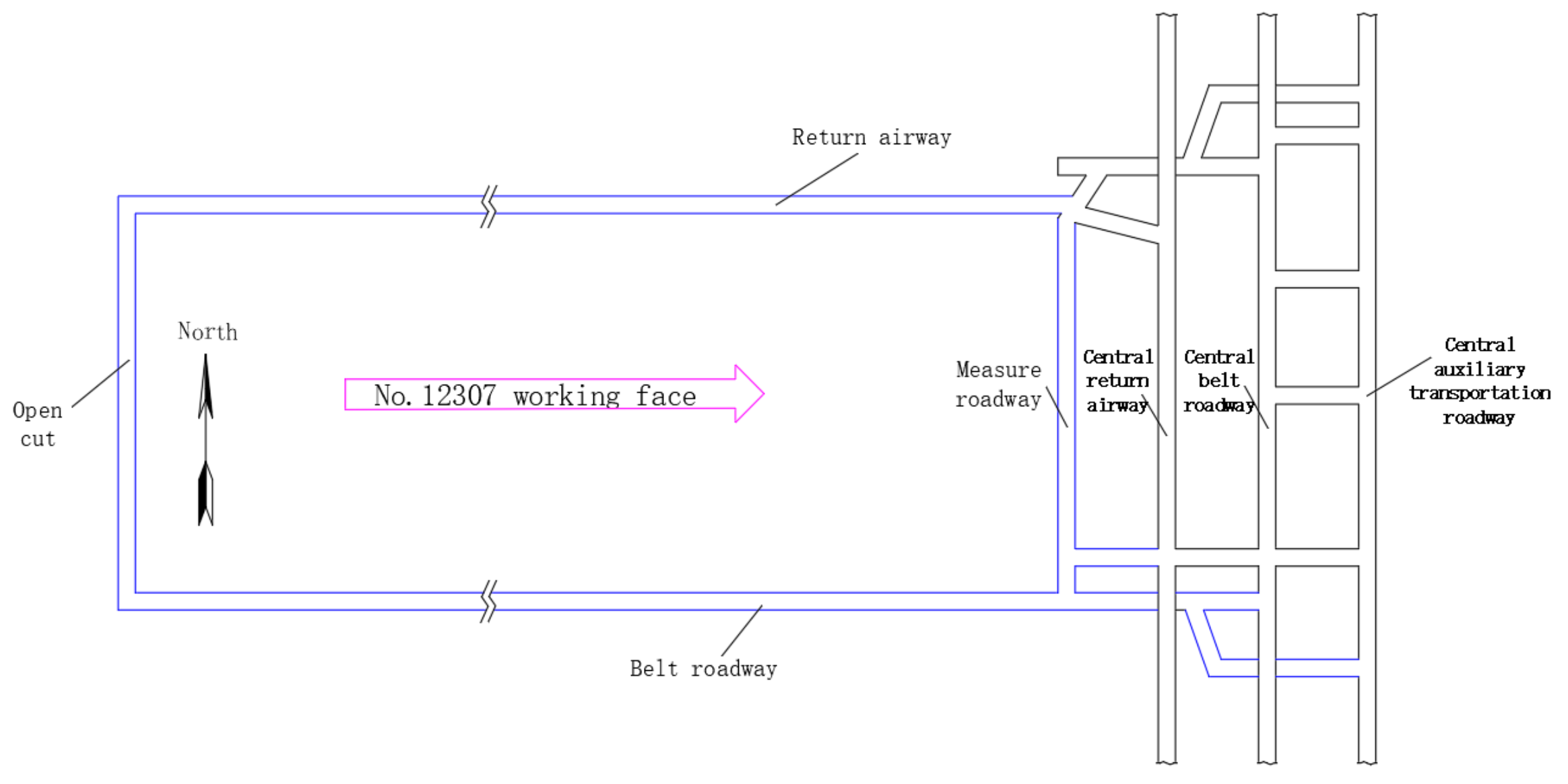
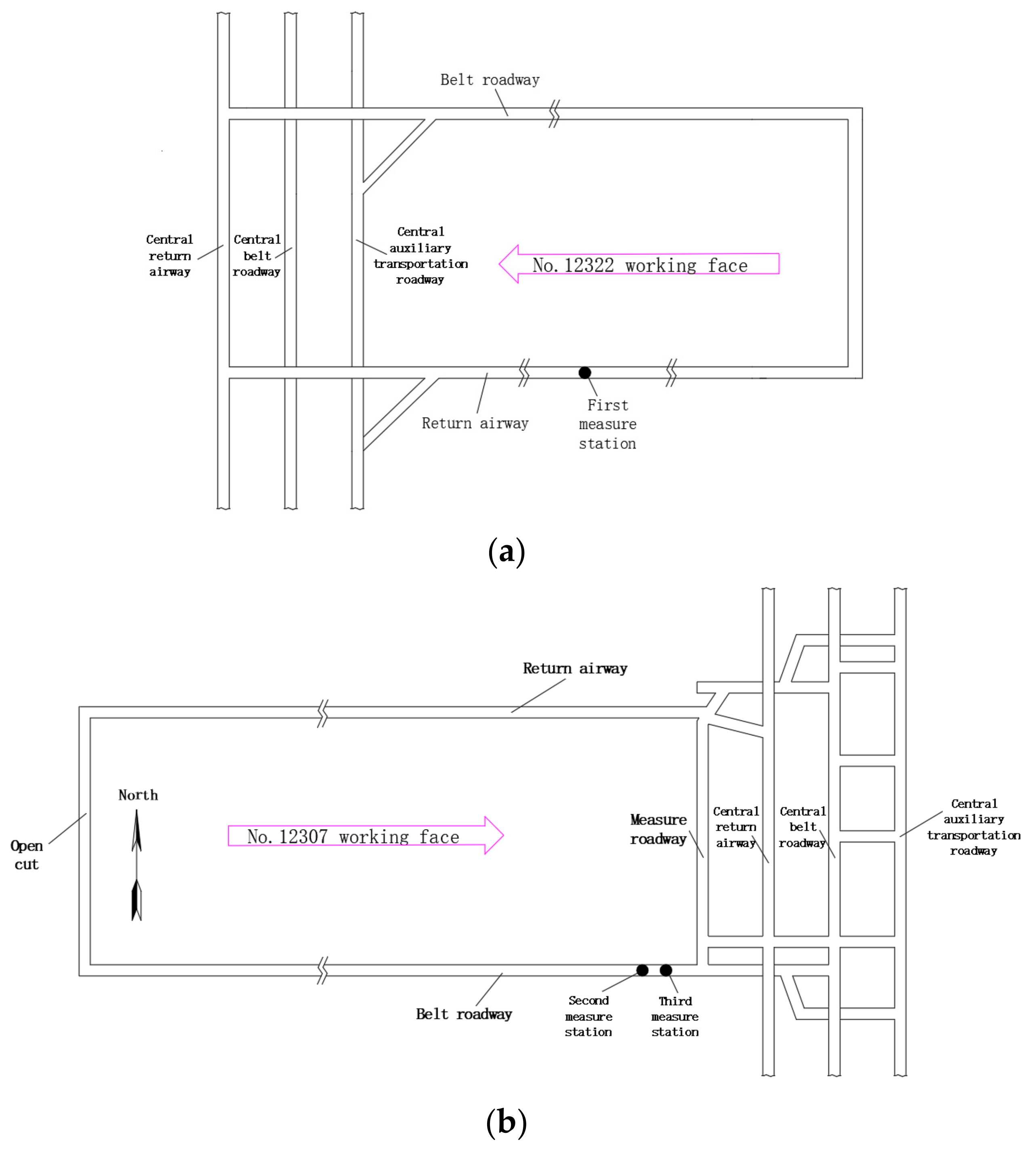
2. Project Overview
3. Geomechanical Parameters and Distribution Characteristics of the Surrounding Rock of the Roadway
3.1. Ground Stress
- (1)
- The maximum horizontal principal stress of the first measurement point is 14.01 MPa, the minimum horizontal main stress is 7.48 MPa, and the vertical stress is 10.43 MPa. The maximum horizontal principal stress of the second measuring point is 12.19 MPa, the minimum horizontal principal stress is 6.22 MPa, and the vertical stress is 10.28 MPa. The maximum horizontal principal stress of the third measuring point is 11.89 MPa, the minimum horizontal principal stress is 6.61 MPa, and the vertical stress is 10.46 MPa. The measured regional data are relatively consistent; the maximum horizontal principal stress is 14.01 MPa, and the maximum value of the minimum horizontal principal stress is 7.48 MPa, but the difference between the maximum and minimum horizontal principal stress is large, and the horizontal stress distribution has obvious directionality. In terms of magnitude, the stress field of the 2# coal seam belongs to the medium stress value area.
- (2)
- The maximum horizontal principal stress of the measuring point is greater than the vertical stress, the minimum horizontal principal stress is the minimum principal stress, and the type of stress field in the measured area is σH > σV > σh type stress field. Relevant studies have shown that the maximum horizontal principal stress has a greater impact on the roof and floor of the roadway than on the two sides of the roadway, while the vertical stress mainly affects the stress and deformation of the two sides of the roadway.
- (3)
- The maximum horizontal principal stress direction of the three measurement points is N78.2° W, N63.5° W, N56.0° W, and the dominant direction of the maximum horizontal main stress is the NWW direction.
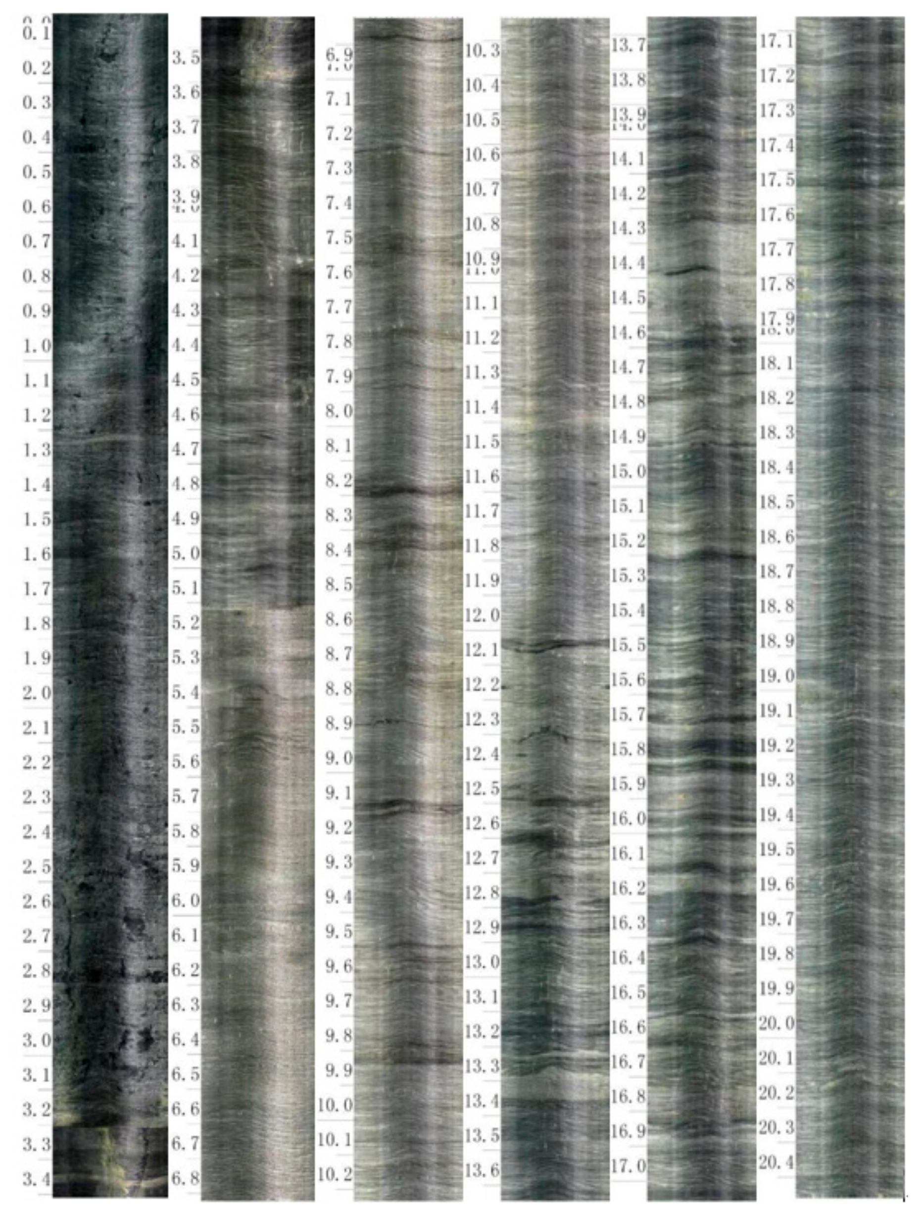
3.2. Surrounding Rock Structure
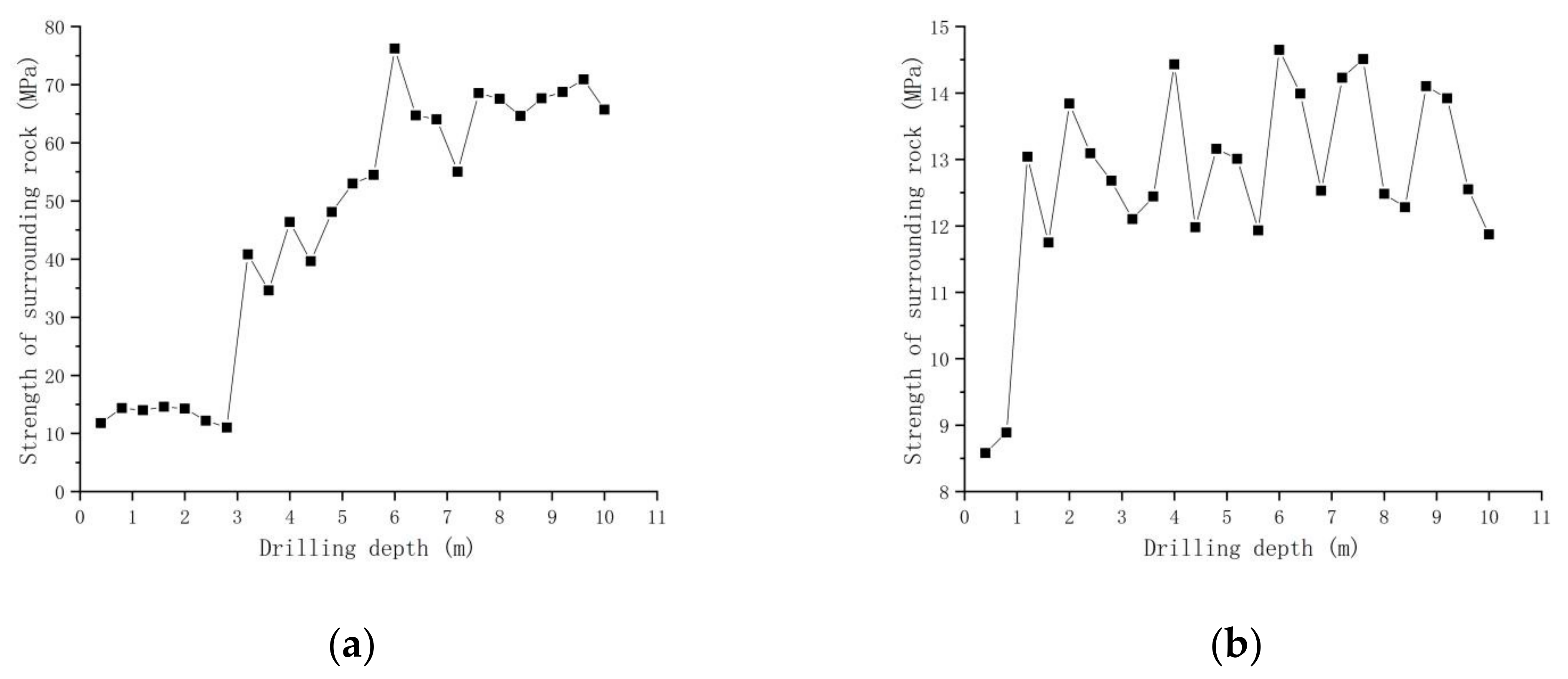
3.3. Surrounding Rock Strength
- (1)
- The top coal is within 3.2 m above the roof of the roadway, the compressive strength is between 11 and 15 MPa, and the average compressive strength is 13.18 MPa, which is small. The range of 3.2~5 m is sandy mudstone, the compressive strength is 34~50 MPa, and the average compressive strength is 41.9 m. In the range of 5 to 10 m, it is fine-grained sandstone, the compressive strength is 50~80 MPa, and the average compressive strength is 64.71 MPa, which is relatively strong. It can be seen that even in the relatively hard and intact rock, the strength of the surrounding rock will fluctuate significantly.
- (2)
- Whether it is the roof or the two sides, the strength difference and fluctuation of surrounding rock are obvious. Notably, when the hole depth is small, the strength of the surrounding rock will increase drastically. The strength of roof surrounding rock increases from 11 Mpa to 40 MPa, and the strength of roadway-surrounding rock rises from 9 Mpa to 13 Mpa. The obvious difference and fluctuation may be caused by the influence of structural planes such as joints, fissures and weak interlayer, damage to the roadway surface and deep surrounding rock due to excavation, which reduces or loses the strength of surrounding rock, and the different properties between rock strata.
4. Numerical Simulation
4.1. Cutting Path Analysis
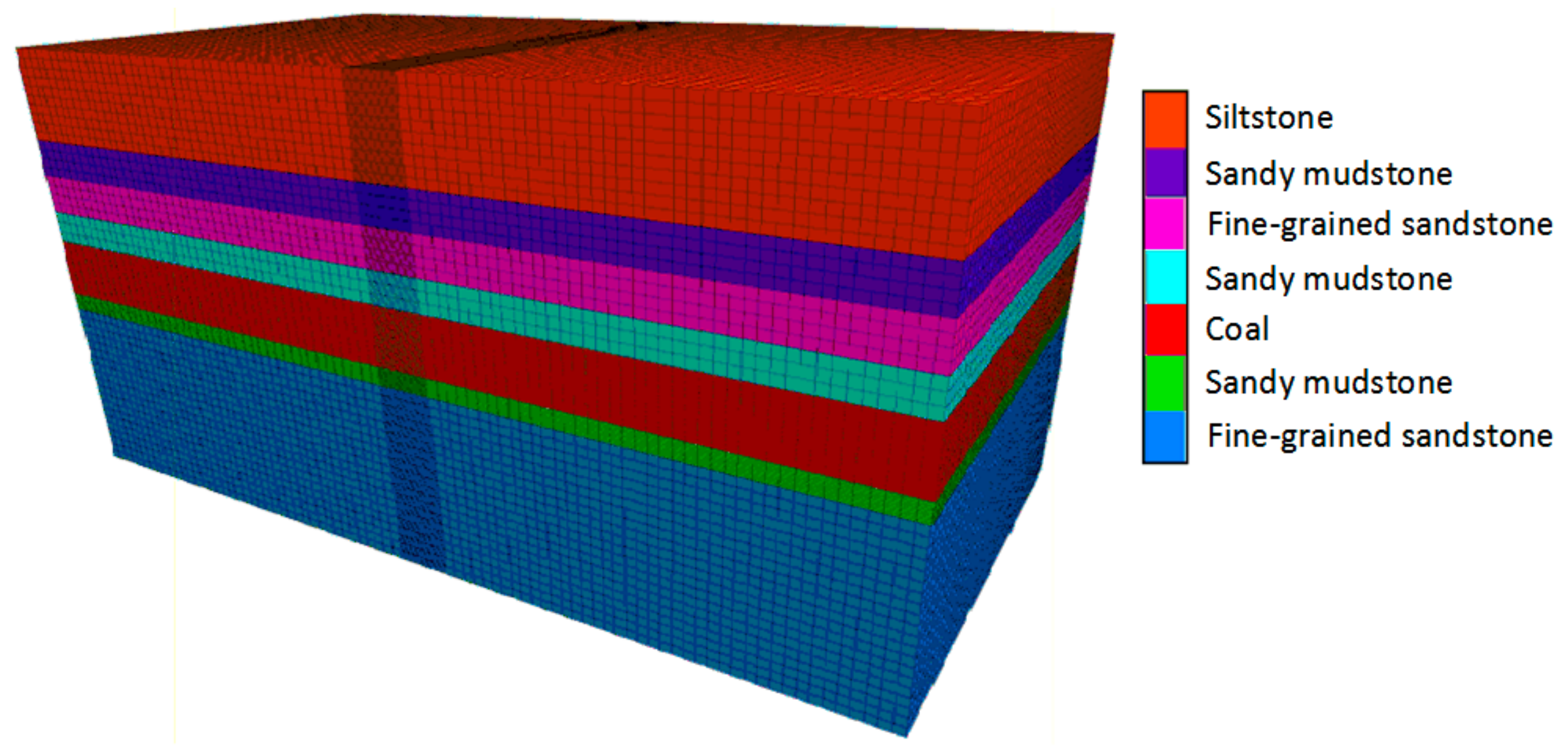
4.2. Simulation Model Building
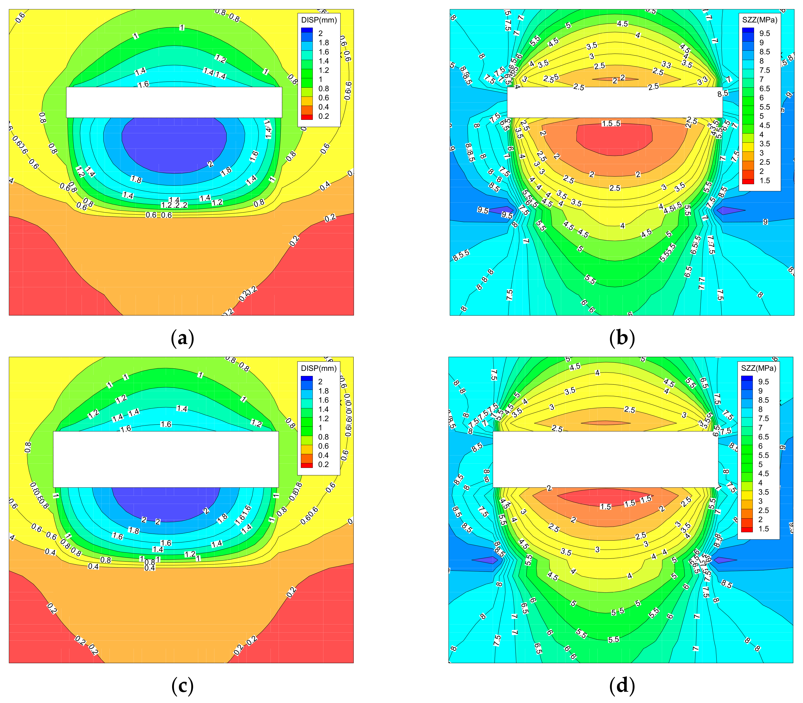
4.3. Analysis of Simulation Results
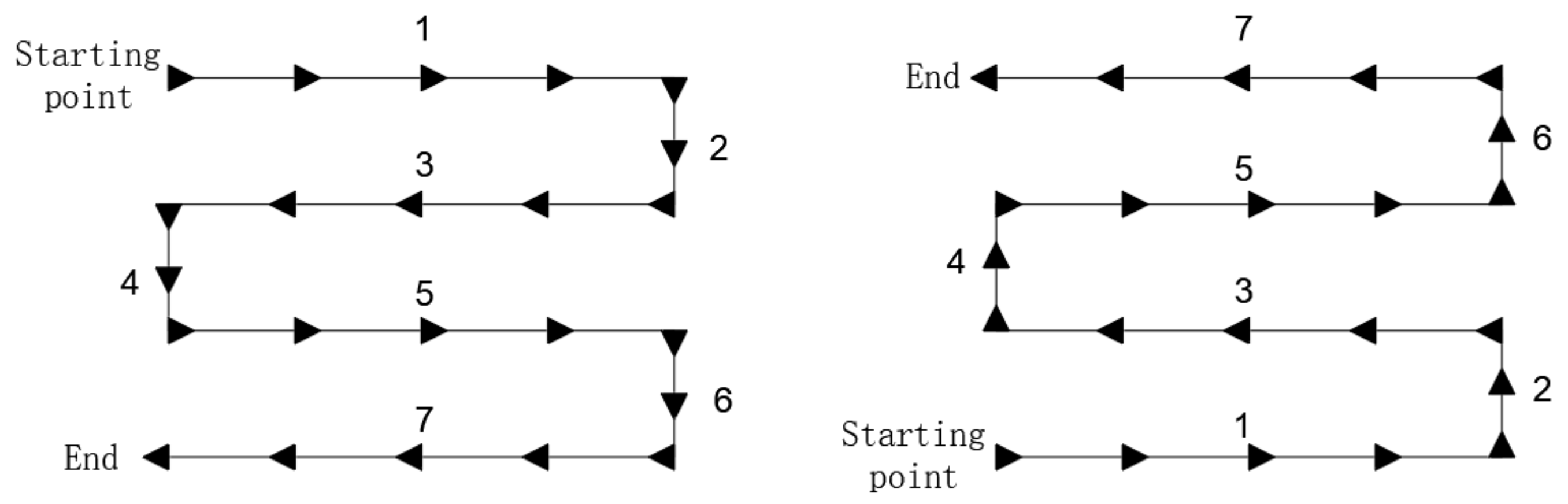
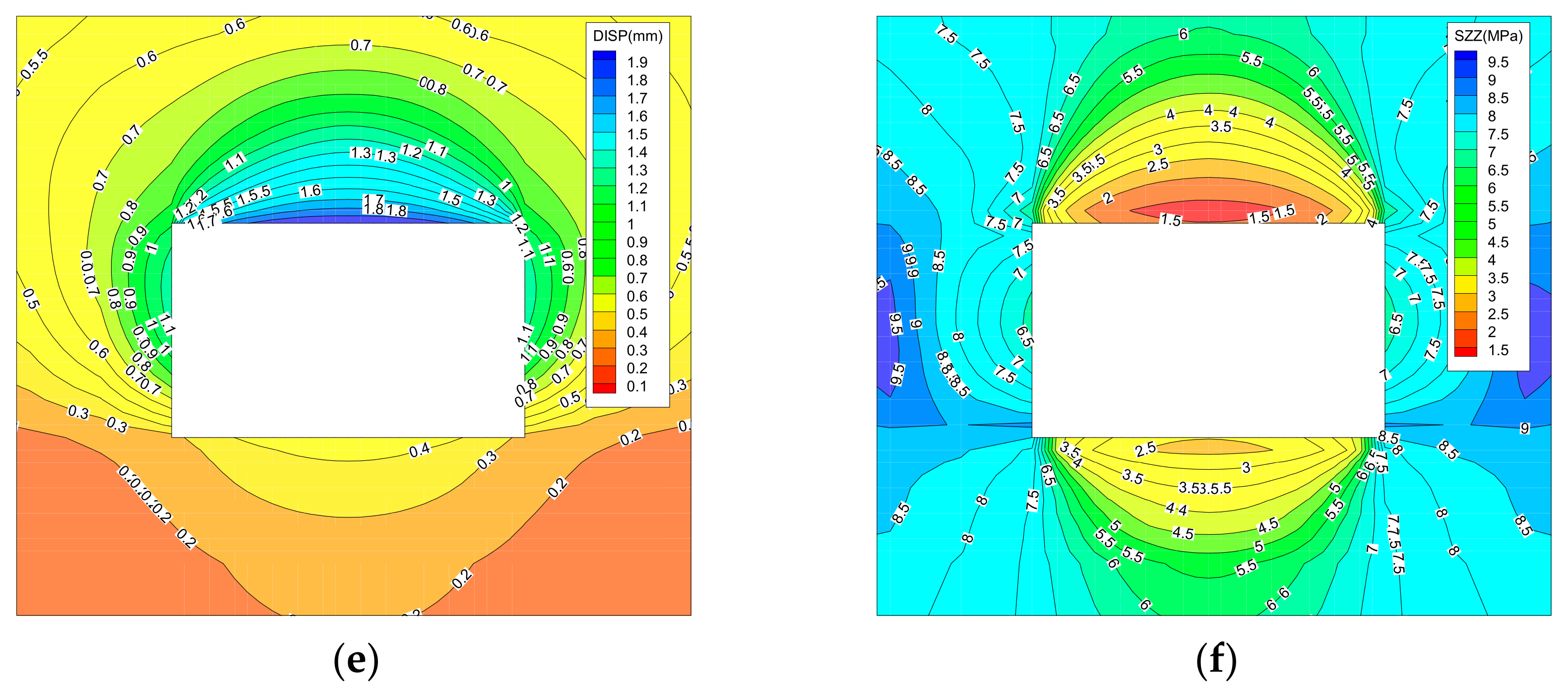
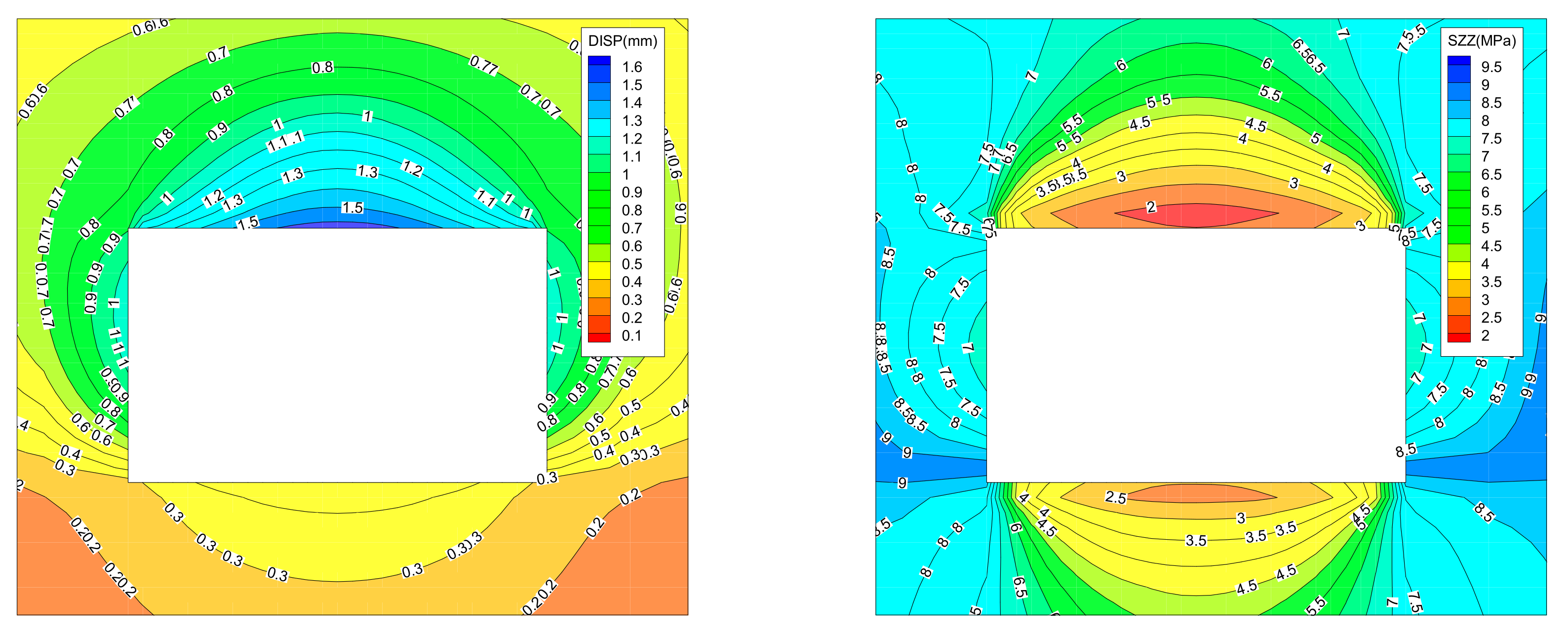
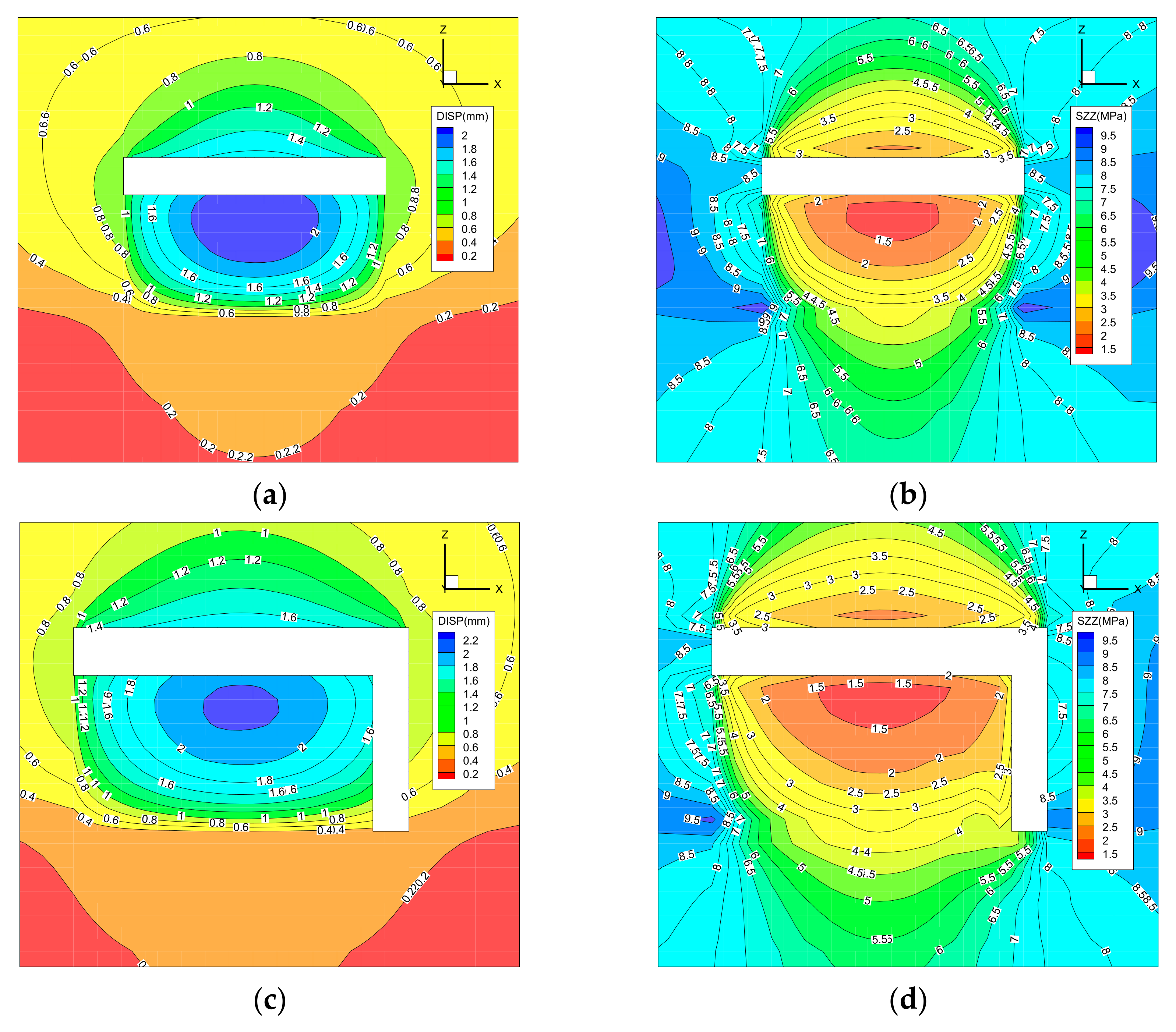
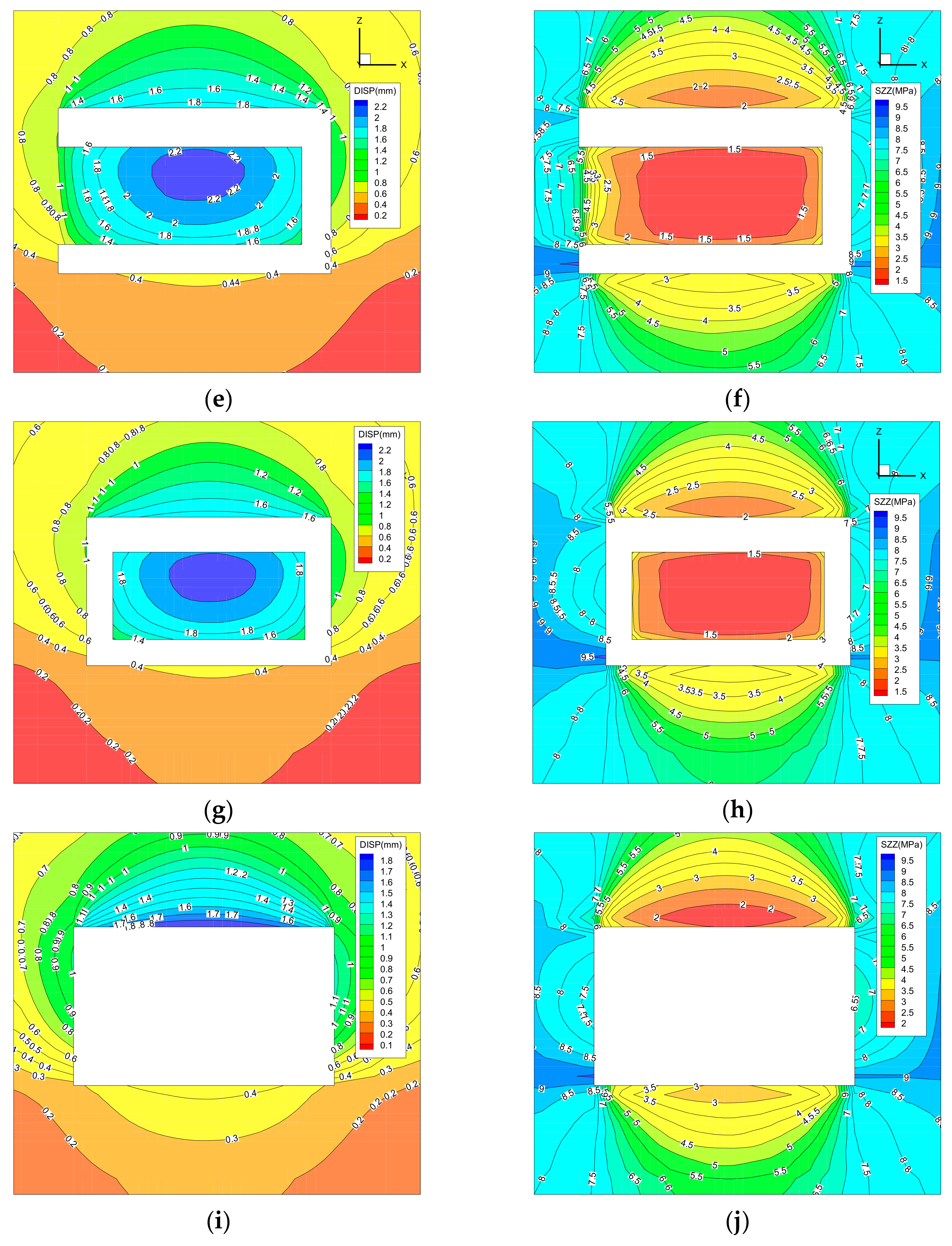
4.3.1. Snake Path
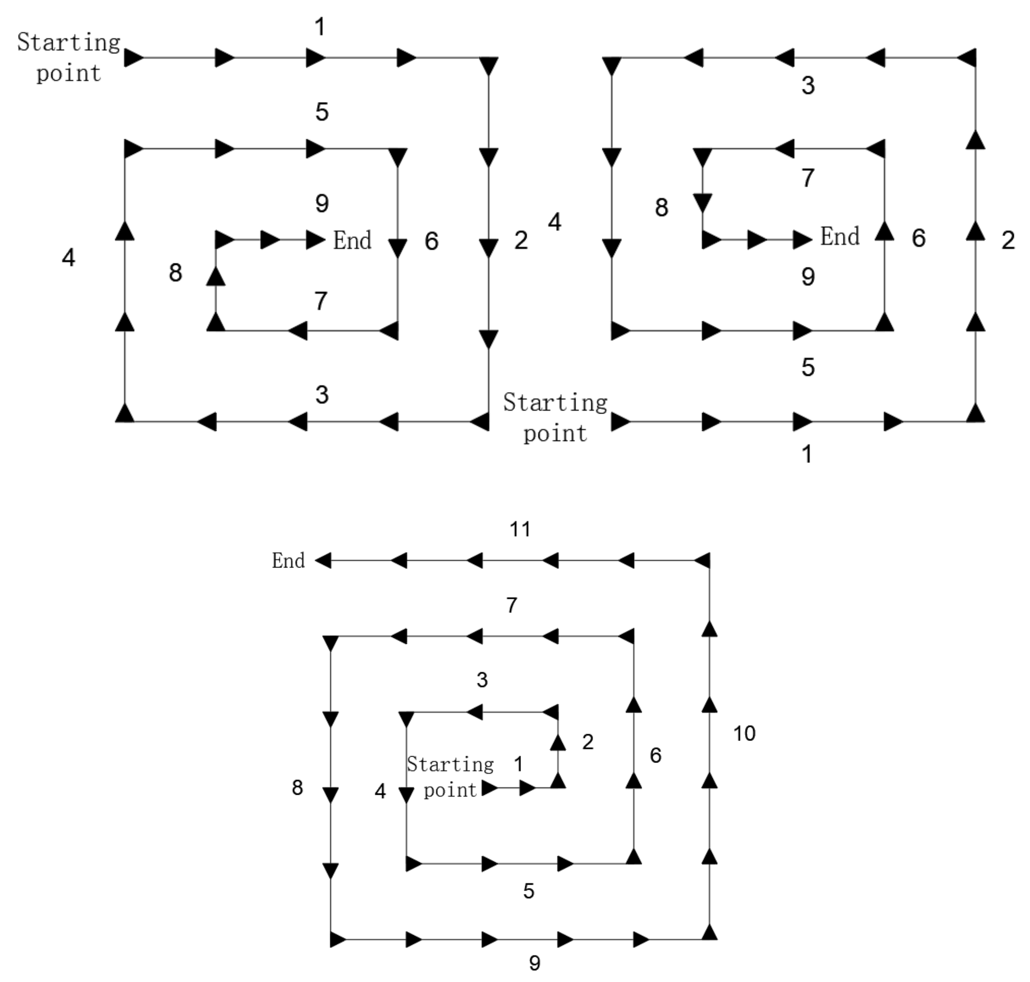
4.3.2. Loop Path
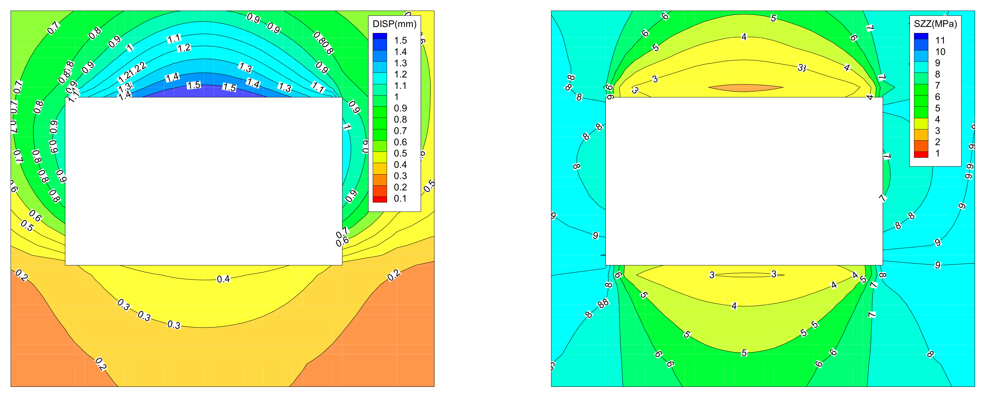
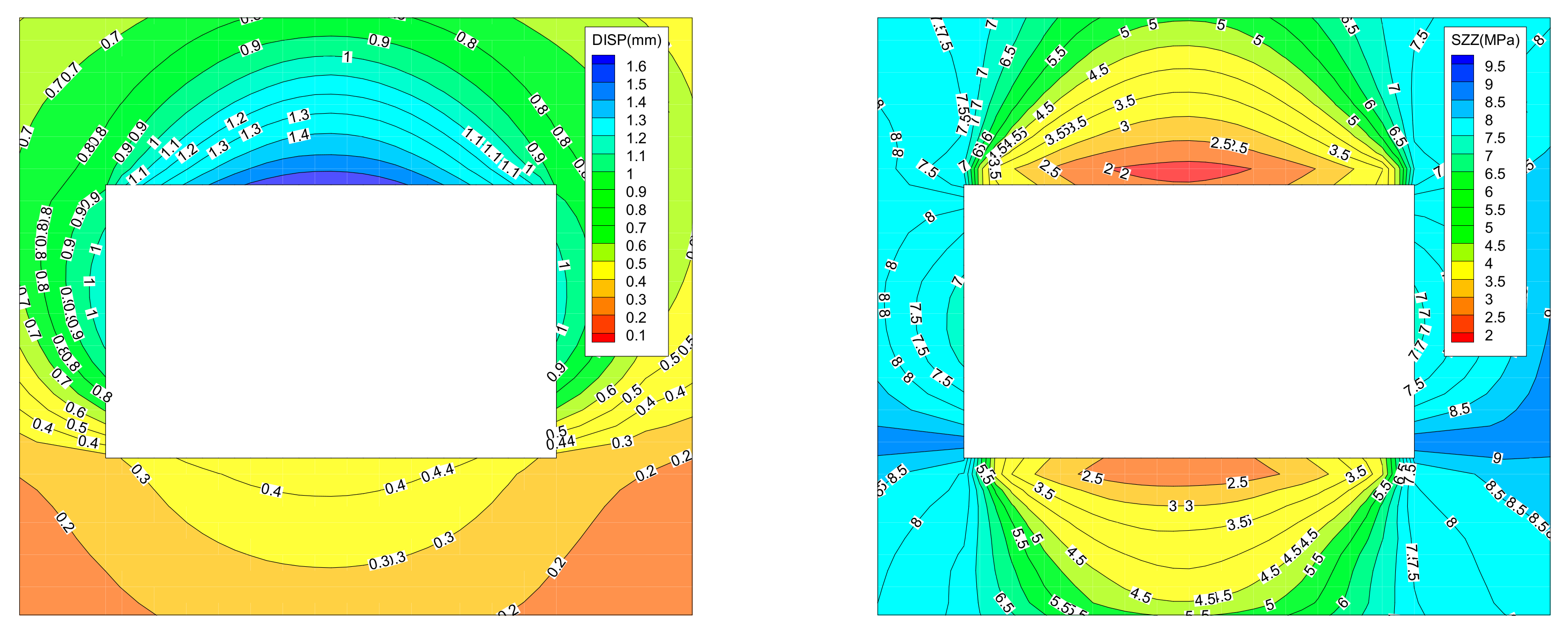
- (1)
- During “clockwise loop” cutting, the maximum displacement of the roof after the first cutting is 160 mm, the maximum displacement of the design roadway section center is 200 mm, the maximum displacement of the roof after the second cutting is 180 mm, and the maximum displacement of the design roadway section center is 220 mm. This is due to the increase in the roof displacement caused by the increase in the forming displacement of the right side after the second cutting. After the third cutting, the roadway floor is formed, and the maximum displacement of the floor is 40 mm, while the displacement of the right upper roof changes little.
- (2)
- During “reverse loop” cutting, the roadway floor is formed after the first cutting, and the floor displacement is small. The maximum displacement in the coal to be cut reaches 200 mm, which is because the roadway floor is fine-grained sandstone and the floor deformation is small. After the second cutting, the forming displacement of the right upper increases to 80 mm, and the displacement of the bottom plate changes less. After the third cutting, the roof is formed, the displacement of the roof increases to 140 mm, and the maximum displacement of the right side increases to 100 mm. This is because when the roof is formed, the support stress of the right side increases, and the deformation increases.
- (3)
- Whether it is “clockwise loop” or “reverse loop” cutting, the left side is formed after the fourth cutting, the displacement of roadway roof changes less, and the displacement of coal to be cut increases. This is because the coal to be cut has been broken after the third cutting. At this time, the left side has played the role of supporting the roof, and the displacement of left side is generated. After the fourth cutting, because the coal to be cut has no force on the surrounding rock of the roadway, with the increase in cutting times, the displacement and deformation of the surrounding rock of the roadway changes less, and the displacement of the coal to be cut changes greatly. At this time, the coal to be cut is relatively broken and easy to cut.
4.4. Cutting Path Determines
5. Industrial Experimentality
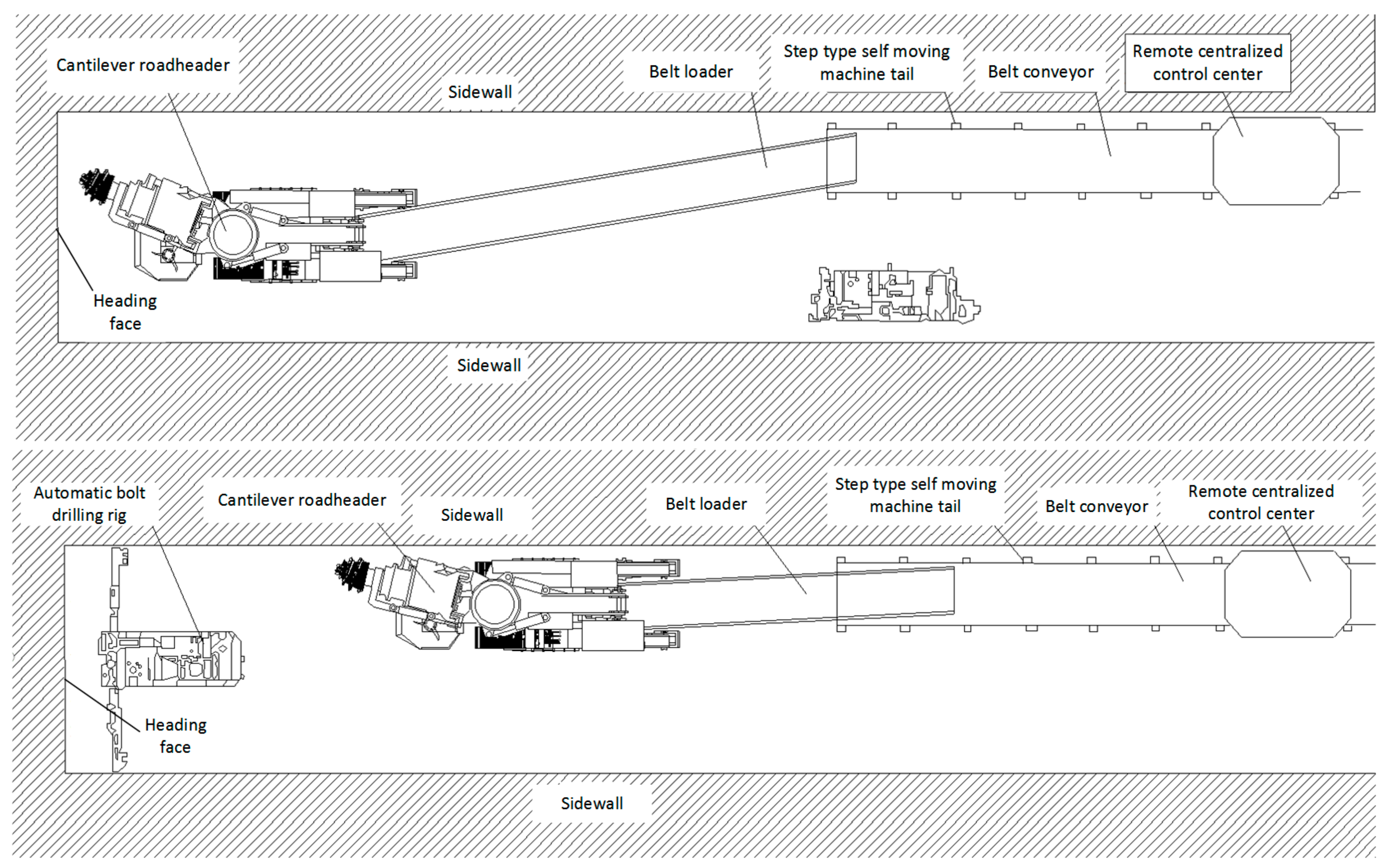
5.1. Excavation Equipment and Technology
5.2. Implementation Effects
6. Conclusions
- (1)
- Representative sites were selected as measurement points to observe the geomechanical parameters and distribution characteristics of the surrounding rocks in the roadway of Wangjialing Coal Mine, so as to provide a parameter basis for numerical simulation.
- (2)
- Based on the observation results, a numerical simulation model was established to study the distribution law of stress meter displacement of roadway-surrounding rock under “snake” and “loop” cutting paths. The simulation results showed that the bottom-up “snake” cutting path and “reverse loop” cutting path were the best.
- (3)
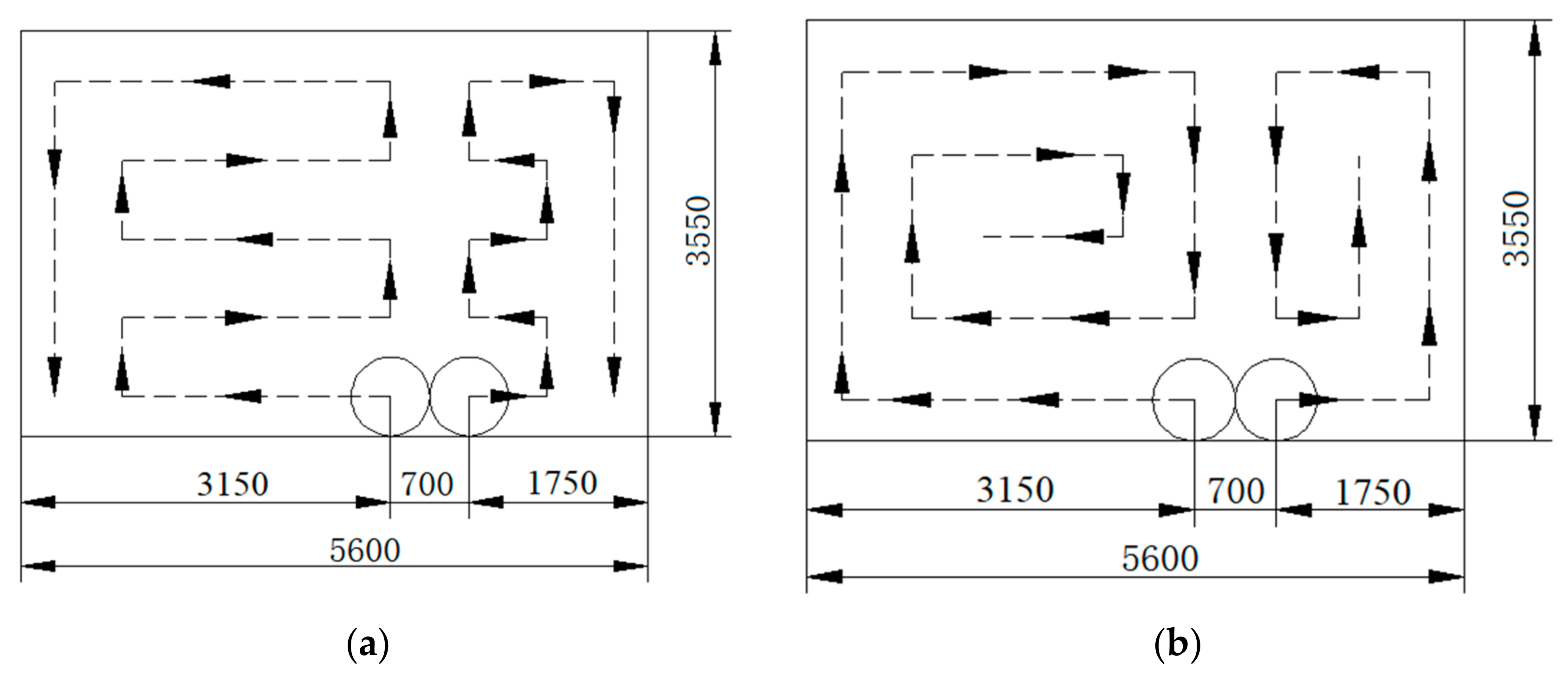
- Combined with the simulation results and the actual situation of the 12307 belt roadway, two cutting schemes were designed (Figure 14). The field test showed that cutting scheme 1 was more conducive to the formation of the roadway, and the single cycle cutting took 34 min, which not only ensures the formation effect of the roadway, but also improves the tunneling efficiency and safety. Therefore, combined with the actual situation of roadway excavation, the numerical simulation analysis method can be used to design the cutting path during roadway excavation.
Author Contributions
Funding
Institutional Review Board Statement
Informed Consent Statement
Data Availability Statement
Acknowledgments
Conflicts of Interest
References
- Milici, R.C.; Flores, R.M.; Stricker, G.D. Coal resources, reserves and peak coal production in the United States. Int. J. Coal Geol. 2013, 113, 109–115. [Google Scholar] [CrossRef]
- Wang, J. Development and prospect on fully mechanized mining in Chinese coal mines. Int. J. Coal Sci. Technol. 2014, 1, 253–260. [Google Scholar] [CrossRef] [Green Version]
- Tang, B.; Cheng, H.; Tang, Y.; Zheng, T.; Yao, Z.; Wang, C.; Rong, C. Supporting Design Optimization of Tunnel Boring Machines-Excavated Coal Mine Roadways: A Case Study in Zhangji, China. Processes 2020, 8, 46. [Google Scholar] [CrossRef] [Green Version]
- Kramadibrata, S.; Simangunsong, G.M.; Widodo, N.P.; Wattimena, R.K.; Tanjung, R.A.; Wicaksana, Y. Rock excavation by continuous surface miner in limestone quarry. Geosyst. Eng. 2015, 18, 127–139. [Google Scholar] [CrossRef]
- Dalgic, S. Influence of weak rocks on excavation of the Beykoz Tueel, Turkey. Eng. Geol. 2000, 58, 137–148. [Google Scholar] [CrossRef]
- Choi, S.O.; Shin, H.S. Stability analysis of a tunnel excavated in a weak rock mass and the optimal supporting system design. Int. J. Rock Mech. Min. Sci. 2004, 41, 876–881. [Google Scholar] [CrossRef]
- Menezes, P.L.; Lovell, M.R.; Avdeev, L.V.; Higgs, C.F., III. Studies on the formation of discontinuous rock fragments during cutting operation. Int. J. Rock Mech. Min. 2014, 71, 131–142. [Google Scholar] [CrossRef] [Green Version]
- Menezes, P.L. Influence of cutter velocity, friction coefficient and rake angle on the formation of discontinuous rock fragments during rock cutting process. Int. J. Rock Mech. Min. Sci. 2017, 90, 3811–3827. [Google Scholar] [CrossRef]
- Menezes, P.L. Influence of rock mechanical properties and rake angle on the formation of rock fragments during cutting operation. Int. J. Adv. Manuf. Technol. 2017, 90, 127–139. [Google Scholar] [CrossRef]
- Bilgin, N.; Demircin, M.A.; Copur, H.; Balci, C.; Tuncdemir, H.; Akcin, N. Dominant rock properties affecting the performance of conical picks and the comparison of some experimental and theoretical results. Int. J. Rock Mech. Min. Sci. 2006, 43, 139–156. [Google Scholar] [CrossRef]
- Fowell, R.J. The mechanics of rock cutting. In Comprehensive Rock Engineering; Hudson, J.A., Ed.; Elsevier: Pergamon, Turkey; Oxford, UK, 1993; pp. 155–175. [Google Scholar]
- Deliac, E.P. Theoretical and practical rules for mechanical rock excavation. In Comprehensive Rock Engineering; Hudson, J.A., Ed.; Elsevier: Pergamon, Turkey; Oxford, UK, 1993; pp. 177–227. [Google Scholar]
- Acaroglu, O.; Ergin, H. The effect of cutting head shapes on roadheader stability. Min. Technol. 2005, 114, 140–146. [Google Scholar] [CrossRef]
- Acaroglu, O.; Ergin, H. A new method to evaluate roadheader operational stability. Tunn. Undergr. Space Technol. 2006, 21, 172–179. [Google Scholar] [CrossRef]
- Ergin, H.; Acaroglu, O. The effect of machine design parameters on the stability of a roadheader. Tunn. Undergr. Space Technol. 2007, 22, 80–89. [Google Scholar] [CrossRef]
- Salsani, A.; Daneshian, J.; Shariati, S.; Yazdani-Chamzini, A.; Taheri, M. Predicting roadheader performance by using artificial neural network. Neural Comput. Appl. 2014, 24, 1823–1831. [Google Scholar] [CrossRef]
- Comakli, R.; Kahraman, S.; Balci, C. Performance prediction of roadheaders in metallic ore excavation. Tunn. Undergr. Space Technol. 2014, 40, 38–45. [Google Scholar] [CrossRef]
- Faradonbeh, R.S.; Salimi, A.; Monjezi, M.; Ebrahimabadi, A.; Moormann, C. Roadheader performance prediction using genetic programming (GP) and gene expression programming (GEP) techniques. Environ. Earth Sci. 2017, 76, 584. [Google Scholar] [CrossRef]
- Seker, S.E.; Ocak, I. Performance prediction of roadheaders using ensemble machine learning techniques. Neural Comput. Appl. 2019, 31, 1103–1116. [Google Scholar] [CrossRef]
- Wang, F.; Zhang, C.; Wei, S.; Zhang, X.; Guo, S. Whole section anchor–grouting reinforcement technology and its application in underground roadways with loose and fractured surrounding rock. Tunn. Undergr. Space Technol. Inc. Trenchless Technol. Res. 2016, 51, 133–143. [Google Scholar]
- Cao, R.; Cao, P.; Lin, H. Support technology of deep roadway under high stress and its application. Int. J. Min. Sci. Technol. 2016, 26, 787–793. [Google Scholar] [CrossRef]
- Yang, S.Q.; Chen, M.; Jing, H.W.; Chen, K.F.; Meng, B. A case study on large deformation failure mechanism of deep soft rock roadway in Xin’An coal mine. China Eng. Geol. 2016, 217, 89–101. [Google Scholar] [CrossRef]
- Ding, Y. The current situation of high efficiency and rapid driving system and development of support equipment. Coal Eng. Coal Eng. 2020, 52, 168–171. [Google Scholar]
- Cha, T. Development trend and situation of speed drivage system in coal mine. Coal Technol. 2021, 40, 30–32. [Google Scholar]
- Liu, C.; Jiang, P.; Wang, Z.; Wei, R.; Luo, C.; Guo, J. Research on current situation of rapid driving technology in coal roadway and its assessment method of application effect. Coal Sci. Technol. 2020, 48, 26–33. [Google Scholar]
- Zhang, C.; Zhao, Y.; Bai, Q. 3D DEM method for compaction and breakage characteristics simulation of broken rock mass in goaf. Acta Geotechnica 2021, 1–17. [Google Scholar] [CrossRef]
- Zhang, C.; Zhao, Y.; Han, P.; Bai, Q. Coal pillar failure analysis and instability evaluation methods: A short review and prospect. Eng. Fail. Anal. 2022, 138, 106344. [Google Scholar] [CrossRef]
- Tsinidis, G.; Pitilakis, K.; Madabhushi, G. On the dynamic response of square tunnels in sand. Eng. Struct. 2016, 125, 419–437. [Google Scholar] [CrossRef] [Green Version]


| Serial Number | Measuring Point Location | H/m | σV/MPa | σH/MPa | σh/MPa | △σ/MPa | k | k1 | k2 | k3 | α |
|---|---|---|---|---|---|---|---|---|---|---|---|
| 1 | No.12322 return airway 1050 m | 434 | 10.34 | 14.01 | 7.48 | 6.53 | 1.04 | 1.35 | 0.72 | 1.87 | N78.2° W |
| 2 | No.12322 belt Roadway 50 m | 428 | 10.28 | 12.19 | 6.22 | 5.97 | 0.90 | 1.19 | 0.61 | 1.96 | N63.5° W |
| 3 | No.12322 belt Roadway 100 m | 432 | 10.46 | 11.89 | 6.61 | 5.28 | 0.88 | 1.14 | 0.63 | 1.80 | N56° W |
| Serial Number | Bulk Modulus /GPa | Internal Friction Angle /° | Tensile Strength /Mpa | Density kg/m3 | Shear Modulus /GPa | Cohesion /MPa | Lithology |
|---|---|---|---|---|---|---|---|
| 1 | 5.94 | 32 | 5.52 | 2700 | 4.05 | 1.53 | Siltstone |
| 2 | 3.65 | 27 | 4.63 | 2500 | 1.82 | 1.35 | Sandy mudstone |
| 3 | 10.35 | 36 | 6.84 | 2800 | 7.74 | 3.15 | Fine-grained sandstone |
| 4 | 3.7 | 27 | 4.54 | 2500 | 1.77 | 1.35 | Sandy mudstone |
| 5 | 1.35 | 23 | 3.00 | 1400 | 0.63 | 0.72 | Coal |
| 6 | 3.6 | 29 | 4.74 | 2500 | 1.89 | 1.35 | Sandy mudstone |
| 7 | 10.35 | 36 | 6.34 | 2800 | 7.74 | 3.15 | Fine-grained sandstone |
| Serial Number | Device Name | Specifications | Quantity |
|---|---|---|---|
| 1 | Roadheader | EBZ-220Z | 1 |
| 2 | Bolt drilling rig | CMM2-25Z | 1 |
| 3 | Belt conveyor | DSJ100/80/2 × 200 | 1 |
| 4 | Self-moving tail of belt conveyor | DWZY1000/1200(A) | 1 |
| 5 | Belt Loader | DZQ100/100/40 | 1 |
| 6 | Dust removal fan | KCS-700D | 1 |
| 7 | Bolt machine | MQT-130 | 4 |
| 8 | Air leg rock drill | YT-28 | 4 |
| 9 | Local ventilator | FBD№7.5/2 × 45 kw | 2 |
| Process | Time/Min |
|---|---|
| Pre-operation inspection | 1 |
| Incoming machine | 2 |
| Bottom cutting | 1 |
| Cutting the left side | 6 |
| Cleaning and transporting float coal | 2 |
| Repair roof, left shoulder socket | 2 |
| Repair the bottom feet of left side | 1 |
| Cleaning and transporting float coal | 2 |
| Adjusting machine | 2 |
| Cutting the right side | 5 |
| Cleaning and transporting float coal | 2 |
| Repair roof, right shoulder socket | 1 |
| Repair the bottom feet of right side | 2 |
| Cleaning and transporting float coal | 2 |
| Return machine | 2 |
| Power outage locking | 1 |
| Total | 34 |
Publisher’s Note: MDPI stays neutral with regard to jurisdictional claims in published maps and institutional affiliations. |
© 2022 by the authors. Licensee MDPI, Basel, Switzerland. This article is an open access article distributed under the terms and conditions of the Creative Commons Attribution (CC BY) license (https://creativecommons.org/licenses/by/4.0/).
Share and Cite
Hu, C.; Zhang, Y.; Yu, R.; Fang, X.; Xu, Z.; Wang, L.; Zhao, B. Research on the Optimization of Cutting Path of Cantilever Roadheader in Large Section Excavation. Sustainability 2022, 14, 5345. https://doi.org/10.3390/su14095345
Hu C, Zhang Y, Yu R, Fang X, Xu Z, Wang L, Zhao B. Research on the Optimization of Cutting Path of Cantilever Roadheader in Large Section Excavation. Sustainability. 2022; 14(9):5345. https://doi.org/10.3390/su14095345
Chicago/Turabian StyleHu, Chengjun, Yong Zhang, Rui Yu, Xinqiu Fang, Ziyue Xu, Lixin Wang, and Baofu Zhao. 2022. "Research on the Optimization of Cutting Path of Cantilever Roadheader in Large Section Excavation" Sustainability 14, no. 9: 5345. https://doi.org/10.3390/su14095345