1. Introduction
Coal mining destroys the equilibrium state of the overburden on the stope, resulting in a series of strata movements such as bending, fracture and caving of overburden. Eventually, the stope is vertically divided into a caving zone, a fracture zone and a bending subsidence zone, collectively called the “three zones”. The caving zone and the fracture zone belong to the water-conducting fracture zone (WCFZ) [
1,
2,
3]. A series of stratum movements induced by coal seam mining can cause certain harm to the environment, which directly leads to surface collapse, soil erosion, and surface building damage [
4,
5]. With respect to the above problems, Peng et al. put forward the stratum control theory and controlled strata by studying the law of overburden movement induced by coal seam mining [
1]. Fan et al. proposed the concept of water conservation coal mining. Afterwards, scholars have carried out a series of theoretical researches accordingly [
6]. Accurate division of the WCFZ in the mining overburden serves as an important basis to evaluate the stability of coal mining under water bodies [
7]. Therefore, it is of great significance to accurately evaluate the development of the WCFZ in the mining overburden for safe mining.
Researches on the WCFZ in the mining overburden generally adopted the methods of on-site measurement, numerical simulation, physical simulation and micro-seismic monitoring [
8,
9,
10,
11,
12,
13,
14]. Xu et al. explored the influence of the position of the main key stratum on the development height of the WCFZ; they proposed the conditions to adopt the empirical equation from the perspective of the position of the main key stratum. Moreover, on this basis, they found a method to predict the height of the WCFZ based on the position of the key stratum [
15,
16]. Peng et al. held that the caving zone and the fracture zone were 2–8 times and 30–50 times as thick as the mining height, respectively [
17]. Guo et al. discussed the process of overburden failure in detail and put forward a new method to calculate the height of WCFZ based on the process of overburden failure migration [
18]. Fan et al. studied the development characteristics of the WCFZ through on-site measurement and physical simulation; they revealed the dynamic evolution characteristic of “development-development-closure” of the mining-induced fractures and discovered the “mud cap effect” revealed by mining failure under thick mud caprock [
6]. Wang et al. proposed a new method and its applicable conditions for the division of the “vertical three zones” of mining overburden based on the key stratum stability and the characteristics of post-fracture movement through physical simulation experiments and the key stratum theory [
19,
20]. These studies provide good ideas for dividing the WCFZ in the mining overburden under general geological conditions and traditional mining conditions.
With respect to the composite structure of hard and soft strata, this study analyzed the critical condition for the breakage of hard and soft strata, put forward a theoretical judgment method and its applicable conditions for the division of the WCFZ based on strata deflection and bending deformation of the overburden composite structure. Then, this theoretical judgment method, numerical simulation method and engineering analogy method were applied to the division of the WCFZ in the mining overburden, and the rationality of this method was verified by comparing the results with the on-site measurement results.
3. CFSHS-Based Height Calculation Method
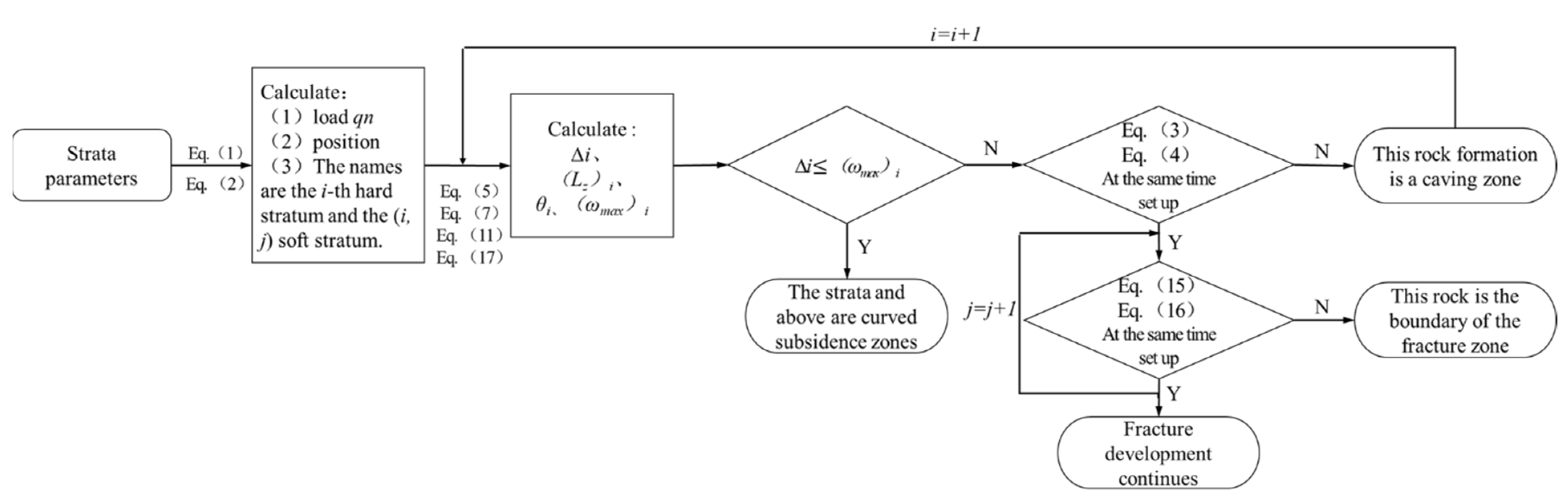
Based on the above bearing stratum judgment, the specific analysis on the stability of the “masonry beam” structure and the stratum bending and subsidence deformation, the method of calculating the height of WCFZ based on the analysis of critical fracturing of soft and hard strata (hereafter referred to as the CFSHS-based height calculation method) was proposed. The specific calculation procedure is as follows:
Step 1: According to the above bearing stratum judgment method, the load borne by the hard stratum and its stratum position are determined. From bottom to top, it is named the i-th hard stratum (i = 1, 2, 3…). The soft stratum borne by it is named the (i, j) soft stratum from bottom to top (i is number of the corresponding hard stratum; j = 1, 2, 3…).
Step 2: With reference to the thickness of the mining coal seam, the height between the stratum and the coal seam, as well as the dilatancy characteristics of the stratum, the height of the free space ∆
i below the stratum is calculated according to Equation (12):
where
is the height of the free space below the
i-th stratum, m;
M is the thickness of the mining coal seam, m;
hi is the thickness of the
i-th stratum, m; (
Kp)
i is the residual dilatancy coefficient of the
i-th stratum.
Step 3: Based on the thickness, tensile strength and bearing load of the hard stratum, the broken block length (Lz)i of the i-th hard stratum is calculated with reference to Equation (5). The rotary angle of the i-th hard stratum θi is calculated with reference to the height of the free space below the stratum and Equation (7).
Step 4: The tensile strength, bearing load and thickness of the hard stratum are substituted into Equation (11) to obtain the maximum bending deformation value of the hard stratum (
ωmax)
i, which is then compared with the height of the free space below it Δ
i:
If Equation (18) is valid, i.e., the height of the free space below the stratum is smaller than its maximum bending deformation value, it is determined that the stratum does not break, only bending deformation occurs, and the stratum is the lower boundary of the bending subsidence zone. Otherwise, if Equation (18) is invalid, i.e., the height of the free space below the stratum is greater than its maximum bending deformation value, the parameters including the rotary angle obtained in Step 3 are substituted into Equations (3) and (4) for judgment. When Equations (3) and (4) are invalid at the same time, the hard stratum belongs to the caving zone. When Equations (3) and (4) are valid at the same time, the hard stratum breaks, and the overburden failure continues to develop upward to the soft stratum which it bears.
Step 5: Determination is made according to the elastic modulus, tensile strength, stratum bearing load and thickness of the (i, j) soft stratum in combination with Equations (15) and (16).
If Equations (15) and (16) are valid at the same time, i.e., when the horizontal tensile strain generated by the loading of the (i, j) soft stratum is greater than its tensile strain limit and the deflection corresponding to the soft stratum is smaller than the height of the free space below it, the soft stratum breaks and the fracture continues to develop upward. Otherwise, the fracture development stops. Analysis is made stratum by stratum accordingly; then the unfractured stratum is found. The height from the stratum to the coal seam roof is the height of the WCFZ.
The following two conditions are the prerequisites for applying the theoretical judgment method: (1) The working face reaches the overburden failure and full mining in the advancing direction, that is, the height of the WCFZ no longer increases with the advancement of the working face. (2) The lithology, stratum thickness and mechanical parameters of the overburden of the working face are fully grasped.
4. Engineering Case Analysis
4.1. Geological Overview
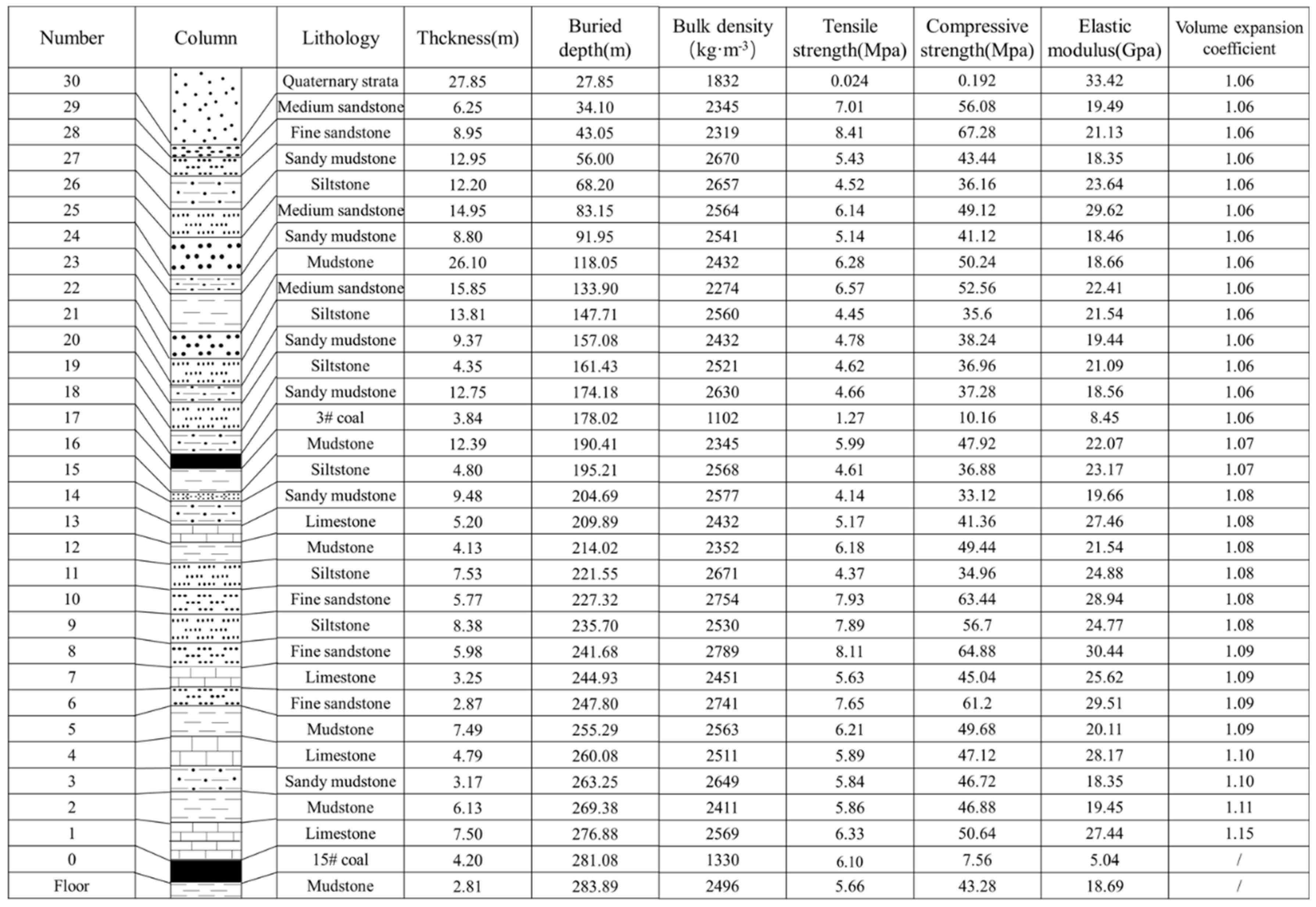
Coal Mine XJ, which belongs to Changzhi Xinjian Coal Industry Co., Ltd., is located in the west of Nansong Town which is 15 km away in the south of shangdang district in changzhi city. The main coal seam in the mine field is coal seam 15, located at the bottom of Taiyuan Group, 98.86 m above coal seam 3, with an average thickness of 4.20 m. It has a simple structure and its whole area is recoverable. The coal seam roof is limestone; the floor is mudstone and sandy mudstone. The histogram of the overburden is given in
Figure 3.
This study designs to observe the working face 15,101 which has a strike length of about 1400 m, an inclined length of about 176 m, a horizontal elevation of +849–920 m, a coal seam dip angle of 0–8° and a buried depth of about 276.88 m. The comprehensive mechanized mining is adopted with a mining height of 4.2 m and an advancing speed of 3.6 m/d, and the overburden reaches the fully mining state in the advancing direction.
The normal water inflow of working face 15,101 is 9.19 m3/h, and the maximum daily water inflow is 16.9 m3/h. It is the largest from June to August and the smallest from January to April, which is directly related to rainfall. The hydrogeological type is medium. Most of the surface is exposed bedrock and partially covered by Quaternary loess. The complexity of mine field structure is a simple type. In coal seam 3, there is no large geological structure and large geological events.
According to the on-site test, the dilatancy coefficient
Kz of the immediate roof in the goaf of working face 15,101 is 1.15; the residual dilatancy coefficient of the upper rock stratum gradually decreases in the logarithmic form. According to researches [
32,
33], the relationship between the average residual dilatancy coefficient
Kp of the stratum and the mining distance from the coal seam
h is:
When h > 100 m, the upper stratum on the working face is hard stratum, which is broken in large blocks and neatly arranged, with a small residual dilatancy coefficient Kz. Calculation reveals that the average residual dilatancy coefficient of the 16th stratum (mudstone) at a mining distance of 98.86 m from the coal seam is 1.07, so the average residual dilatancy coefficient of the 17th stratum and its upper strata shall be smaller than 1.07; hence both are set as 1.06.
The thickness and mechanical parameters of strata can be obtained from the geological drilling data of the working face (
Figure 4).
4.2. Engineering Case of the CFSHS-Based Height Calculation Method
According to the CFSHS-based height calculation method as well as Equations (1) and (2), the load and position of the bearing stratum in the overburden were calculated; the hard stratum and its bearing soft stratum were named from bottom to top. With reference to Equation (12), the free space height ∆
i under the stratum was calculated, and the results are listed in
Table 1.
Based on the mechanical parameters of hard strata and the above Equations (5)–(8) and (11),
Lz,
θ,
Lc and
ωmax of hard strata can be obtained (
Table 2).
The height of the cavity below the first stratum is 1.50 m, and the bending subsidence deformation before the initial breakage is 9.6 mm. They were substituted in Equation (18) to determine whether that the first hard stratum breaks. Next, the parameters of the first hard stratum were substituted into Equations (3) and (4) to determine whether the first hard stratum can form a stable masonry beam structure. Therefore, the first hard stratum is the boundary stratum under the fracture zone, and the height of the caving zone is the height of the first hard stratum from the coal seam, which is 21.59 m.
The above steps were repeated on the 2nd, 3rd and 4th hard strata. Since the mining coal seam is thick and the 2nd and 3rd hard strata are close to the coal seam, cavities still exist under the 2nd and 3rd hard strata, whose heights are greater than its bending subsidence deformation value. Therefore, the 2nd and 3rd hard strata break, and the overburden failure continues to develop upward. In judging the 4th hard stratum, the cavity under the 4th hard stratum has been filled, which prevents the bending deformation of the 4th hard stratum from occurring, so the 4th hard stratum will not be damaged. Preliminary judgment holds that the height of the overburden failure in the working face 15,101 is between the 3rd and the 4th hard strata, i.e., 49.56–81.67 m.
In summary, there are four soft strata between the 3rd and the 4th hard strata. The four soft strata were judged from bottom to top with reference to Equations (15) and (16). It can be concluded that when the (3, 1) soft stratum is under load, its deflection value is not smaller than the free space height below it, so the soft stratum does not break, and the fracture development stops. Therefore, the (3, 1) soft stratum is the boundary stratum of the bending subsidence zone.
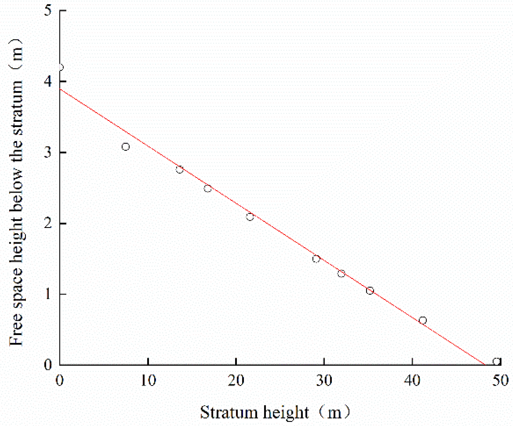
In addition, to explain the relationship between the free space height and the stratum height below the stratum more intuitively,
Figure 5 gives the relationship curve between the free space height and the stratum height. The WCFZ develops to the 3rd hard stratum, and the intersection of the curve and the horizontal axis is the maximum development height (49.56 m) of the WCFZ.
In conclusion, according to the proposed method, the height of the caving zone above the working face 15,101 of coal mine XJ is 21.59 m, and the development height of the WCFZ is 49.56 m. The (3, 1) soft stratum and its above strata belong to the bending subsidence zone (227.32 m thick).
4.3. Engineering Measurement and Analysis
4.3.1. Observation Scheme Design
Abundant aquifers exist in the overburden of most working faces in the mine. Considering this fact, with the working face 15,101 as an engineering case, the height of the WCFZ was detected and analyzed by a borehole television, and the development law of the WCFZ was analyzed by numerical simulation, which provided a basis for safe mining.
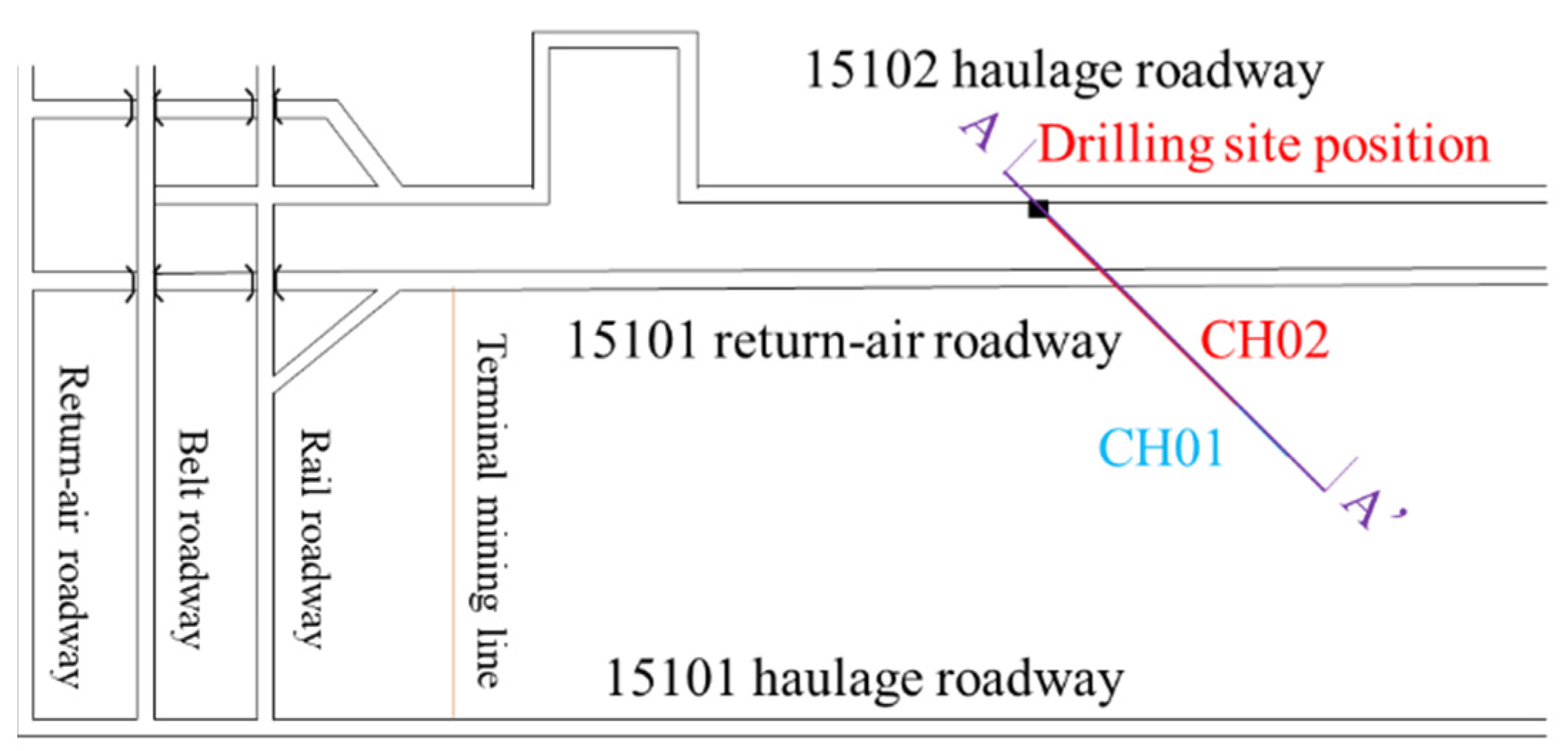
According to the theoretical calculation results, the development height of the WCFZ in the working face 15,101 is 49.56 m, so attention should be paid to the observation of fracture development in this range and the development of the WCFZ to the maximum value consumes 1–3 months. Therefore, considering the actual situation of the working face, the observation date is 43 days after recovery, and the observation site is located in the transportation lane of the working face 15,102, which is about 700 m away from the stopping line. The location of the drilling site is shown in
Figure 6, and the drilling parameters are listed in
Table 3.
4.3.2. Observation Method
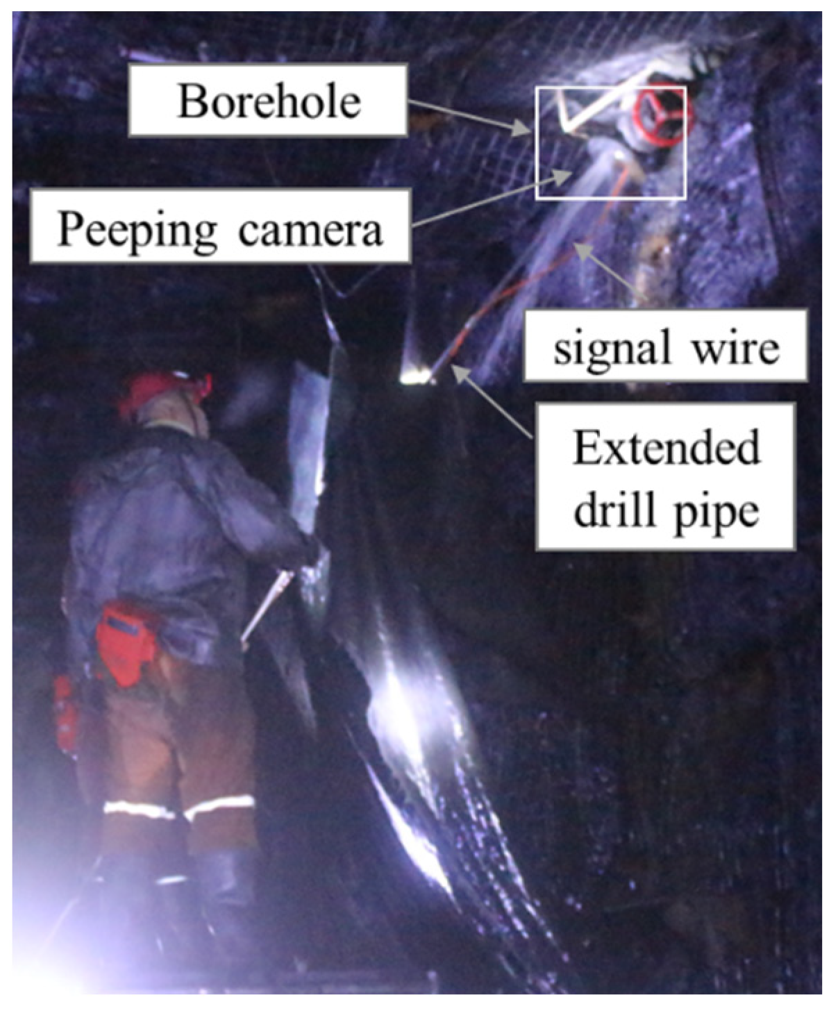
This observation adopted the borehole television from Tianchen Geophysical Exploration Company (Wuhan, China) to visually measure the development of the WCFZ. The borehole television is composed of a peeping camera, a recorder, an extended drill pipe and an imager. During observation, the camera and the imager are connected through a signal wire; the camera then extends to the depth of the borehole by the extended drill pipe to transmit the images of fracture development in the borehole (
Figure 7, an on-site photo).
4.3.3. Analysis on the Observation Results
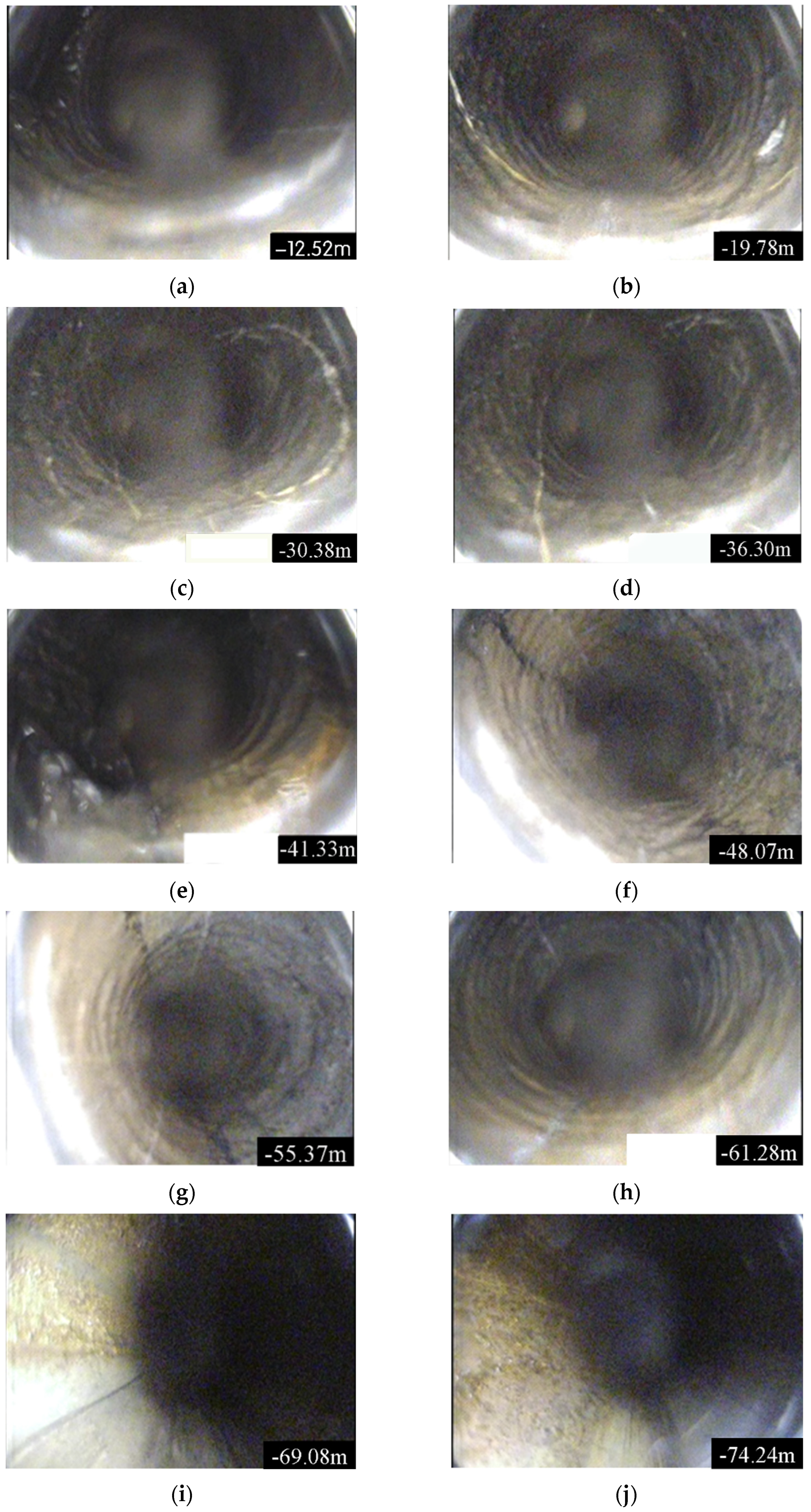
Figure 8 shows the observation results of mining overburden fractures through the CH02 Borehole. The figures in the right bottom of photos are the distances from the camera to the borehole orifice, and the figures below are the vertical distances between the camera and the coal seam roof.
According to the on-site observation records,
Figure 8a,b show the situations of mining overburden within the drilling depth of 12.52–19.78 m, which are 10.25–16.20 m high from coal seam 15 and are above the protective coal pillars between two adjacent working faces. The overburden sees no obvious mining-induced fracture, indicating that the borehole in this range has not entered the fracture zone.
Figure 8c,d show the situations of mining overburden with the drilling depth of 30.38–36.30 m, which are 24.88–29.73 m high from coal seam 15. Notable mining-induced fractures begin to emerge in the overburden, and become increasingly obvious as the drilling is approaching the goaf center. The stratum in
Figure 8d is seriously damaged;
Figure 8e,f illustrate the situations of mining overburden within the drilling depth of 41.33–48.07 m, which are 33.85–39.37 m high from the coal seam 15. Obvious mining-induced fractures can be observed in the strata in this range, suggesting that the strata are significantly affected by mining. However, compared with the overburden of 36.30 borehole depth, the overburden of the drilling depth of 41.33–48.07 m are less damaged and present a certain regularity, and obvious separation occurs at the junction of some adjacent strata.
Figure 8g,h show the situations of mining overburden within the drilling depth of 55.37–61.28 m, which are 45.35–50.19 m high from coal seam 15. According to the detection results, as the height from the coal seam increases, fractures become less developed. The distance and the development degree of fractures are negatively correlated, that is, in this range, the influence of mining on the strata weakens as the height from the coal seam increases. When the borehole depth reaches 69.08 m (
Figure 8i), that is, when the height from the roof of coal seam 15 is greater than 56.58 m, no obvious mining-induced fracture is found in the rock stratum. With the continuous advancement of the probe, when the borehole depth reaches 74.24 m (
Figure 8j), i.e., when the height from the roof of coal seam 15 is beyond 60.08 m, no obvious mining-induced fracture is detected. In summary, the mining overburden of the working face 15,101 develops to 69.08 m borehole depth, and the distance from the roof of coal seam 15 is 56.58 m, that is, the height of the WCFZ detected by the CH02 Borehole is 56.58 m.
Based on the measured results, the height of the caving zone in the goaf of the 15,101 working face is 29.73 m; the height of the WCFZ is 56.58 m; and the thickness of the bending subsidence zone is 220.30 m.
Then the calculation results of the above theoretical judgment method of the “vertical three zones” of mining overburden were contrastively analyzed with the on-site measured results. It can be found that the calculation results of the theoretical judgment method (the height of the caving zone 21.59 m, the development height of the WCFZ 49.56 m, and the thickness of the bending subsidence zone 227.32 m) are similar to the measured results, which verifies the rationality and practicability of the theoretical judgment method.
4.4. Numerical Simulation Analysis
To verify the rationality of the above analytical results, the geological mining conditions of the fully mechanized mining face 15,101 in coal mine XJ served as the background to simulate the caving and fracture characteristics of the mining overburden, and the migration process of the overburden failure was simulated by 3DEC discrete element simulation software.
4.4.1. Model Design
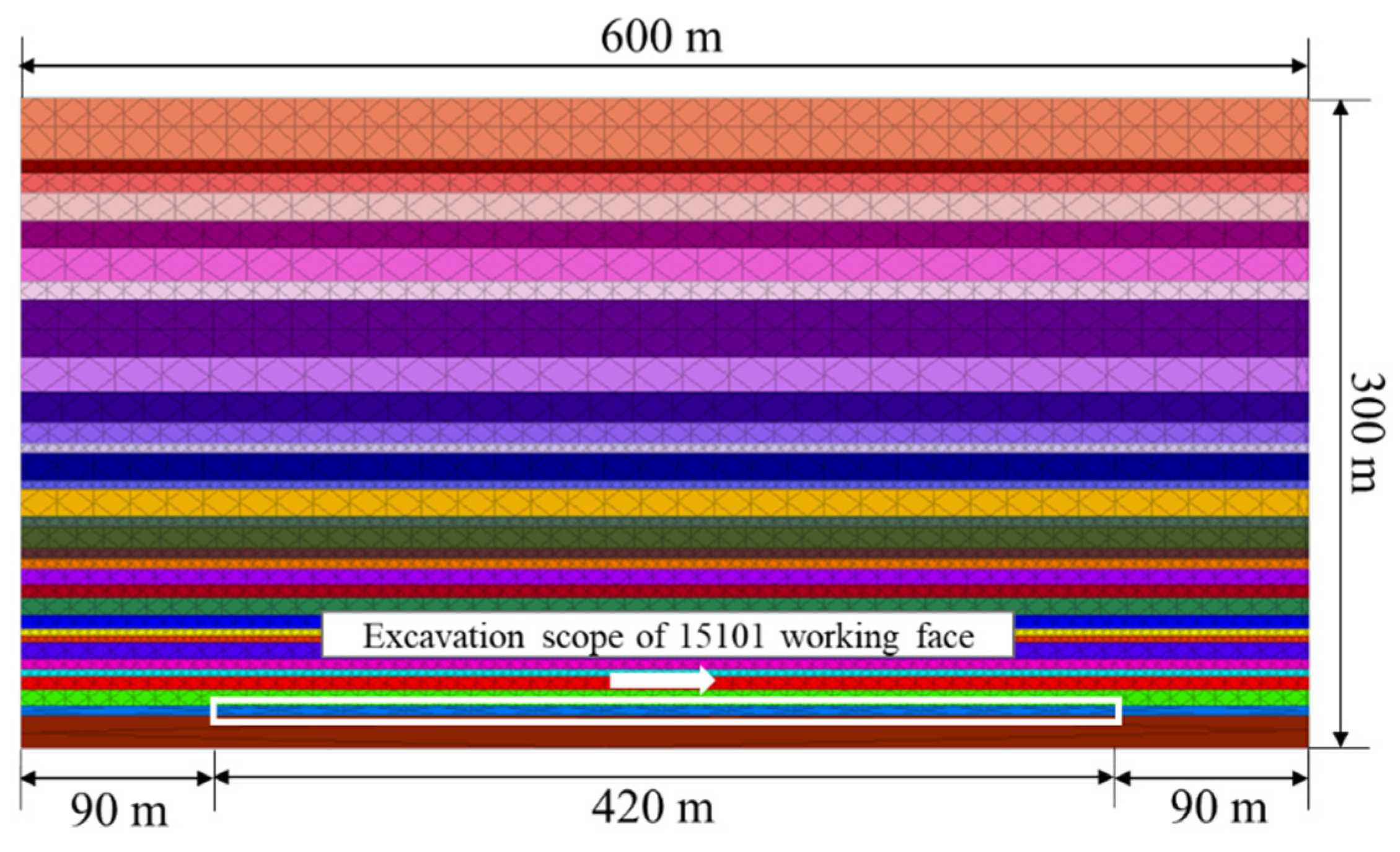
Based on the actual mining data of the fully mechanized face 15,101 in coal mine XJ, a 3DEC numerical calculation model was established. The advancing length of the working face is 420 m, which is extended outward by 180 m along the working face to prevent the influence of the model boundary on the calculation results. The model size is 600 m × 1 m × 300 m (length × width × height) (
Figure 9). The simulated working face was excavated by 30 m each time, a total of 14 excavations.
In the numerical model, the Mohr-Coulomb model was selected as the block constitutive model, and the Coulomb slip model was selected as the joint constitutive model. The left and right boundaries of the model were fixed in x direction displacement, the front and rear boundaries fixed in y direction displacement and the bottom boundary fixed in z direction displacement. According to the experimental data and model calibration, the physical and mechanical parameters of the overburden were determined (
Table 4).
4.4.2. Simulation Results and Analysis
With the advancement of the working face, the caving form of the overburden is shown in
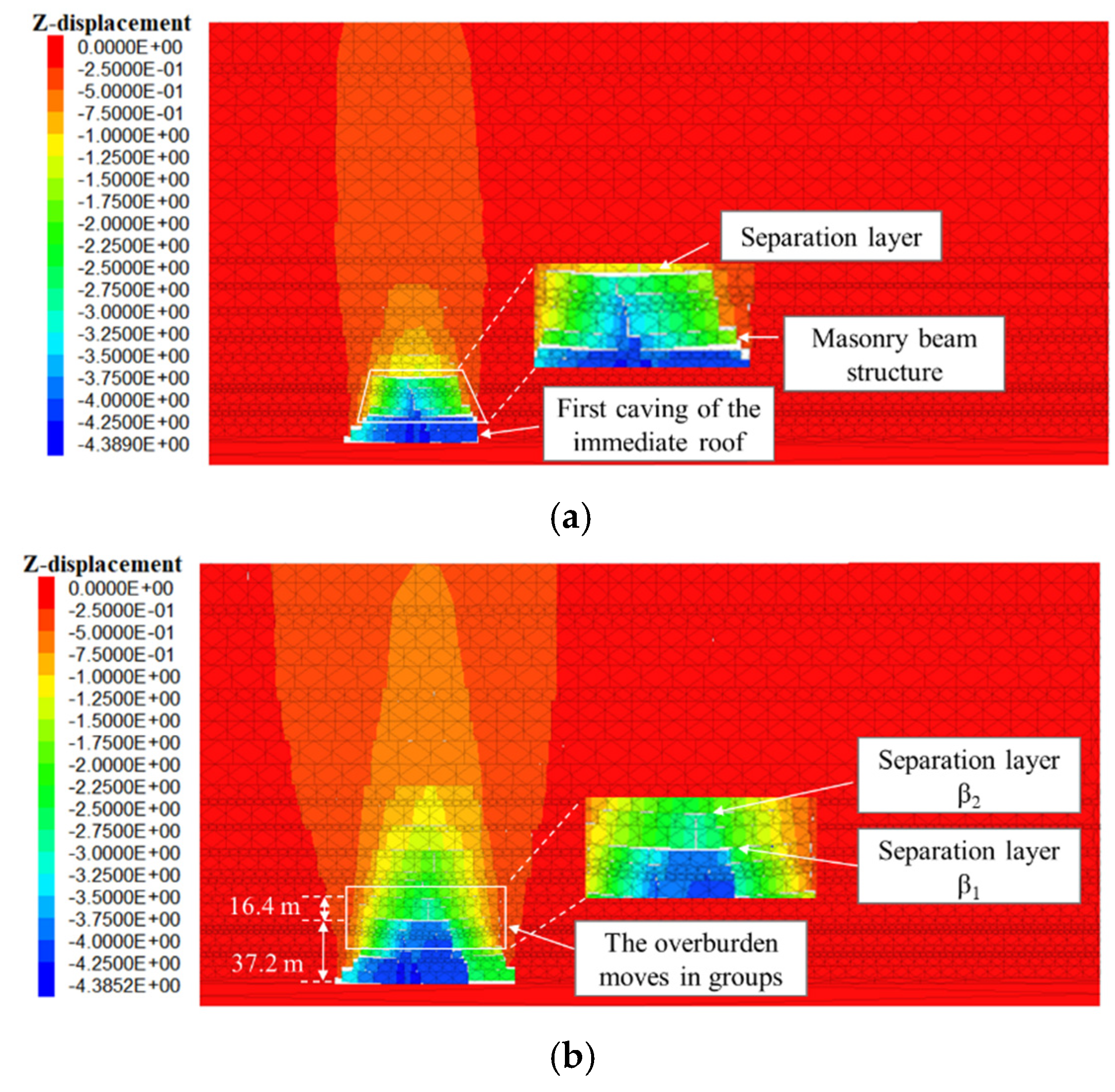
Figure 10. When the working face advances to 90 m (
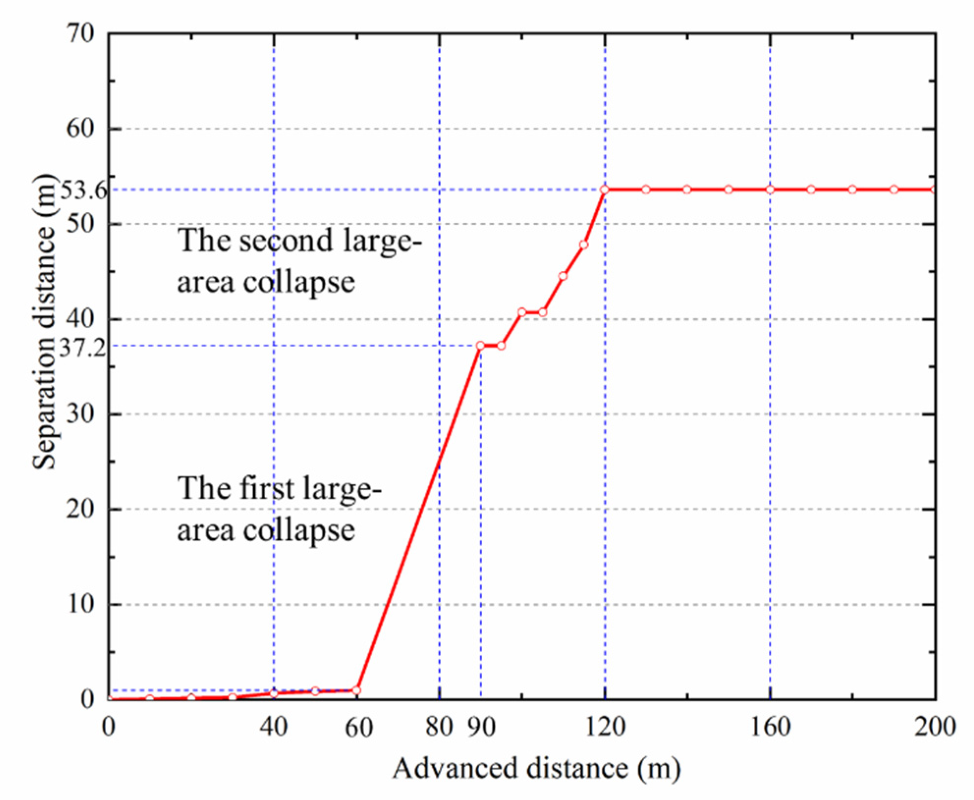
Figure 11a), the overburden begins to cave in a large area, with 4.39 m maximum vertical displacement; the broken limestone forms a masonry beam structure. At this time, the overburden above the coal seam is separated, with 37.2 m separation height. When the working face advances to 120 m (
Figure 11b), the overburden further migrates in a large area, and the separation develops upward to 53.6 m. When the working face advances to 150 m (
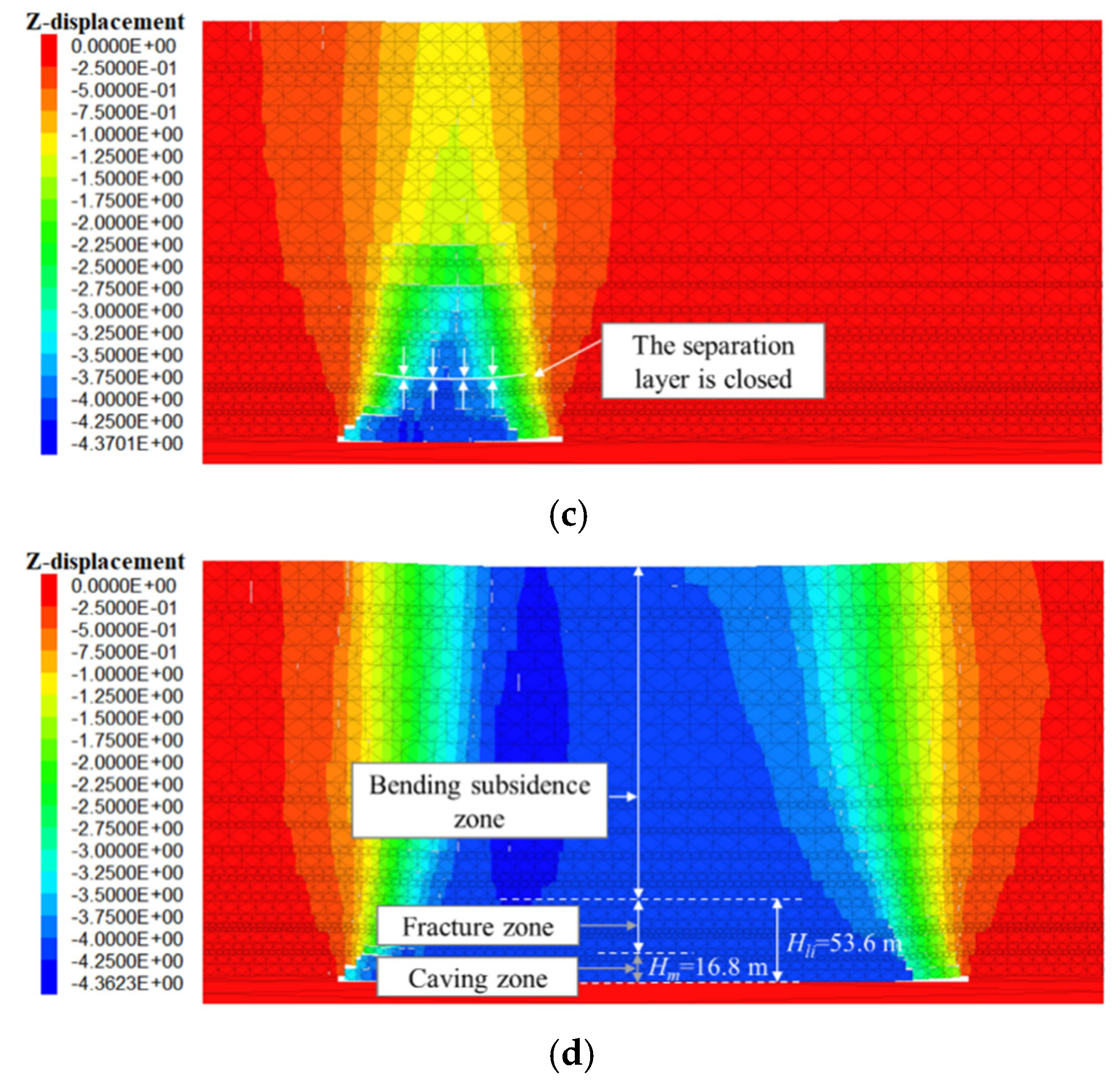
Figure 11c), the lower separation layer is closed. When the working face is excavated to 420 m (
Figure 11d), the separation layer does not develop upward further; according to the closure state of the vertical fractures in
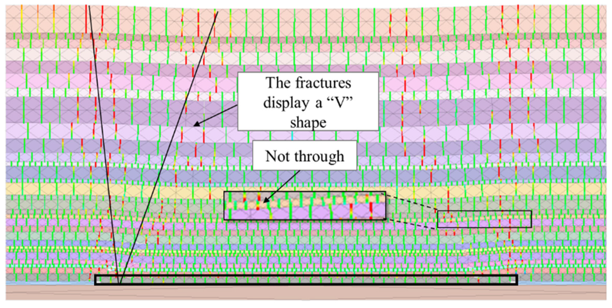
Figure 12 (the red and green represent open and closed fractures respectively), the following conclusions can be obtained: (1) when the working face 15,101 reaches the full mining state in the advancing direction, the overburden migrates and the fractures are closed again; in the goaf middle, the number of closed fractures decreases from the middle to the edge, and the fractures display a “V” shape on the edges of both goaf sides. (2) The vertical interpenetrated fractures of the overburden finally develop to the 53.6 m fine sandstone above the coal seam.
The above numerical simulation experiment leads to the following conclusions: (1) Overburden failure migrates upward in the form of separation layer. When the bending deformation of the stratum below the separation reaches its deformation limit, it interpenetrates the vertical fractures of the overburden, and finally forms a complete overburden water-conducting channel. (2) The upward development of the overburden failure is affected by the hard stratum, so the overburden moves in groups. (3) The numerical simulation reveals that the water-conducting fracture zone is 53.6 m high.
4.5. Scope of Application
This model is a theoretical model, and the application of this model is limited. When the movement of strata above gob is only affected by self-weight and overburden pressure, this model is is applied well. But when a place has a wide range of geological structure (e.g., fault, folds) or geological events (e.g., earthquake), this model will be not suitable.
5. Conclusions
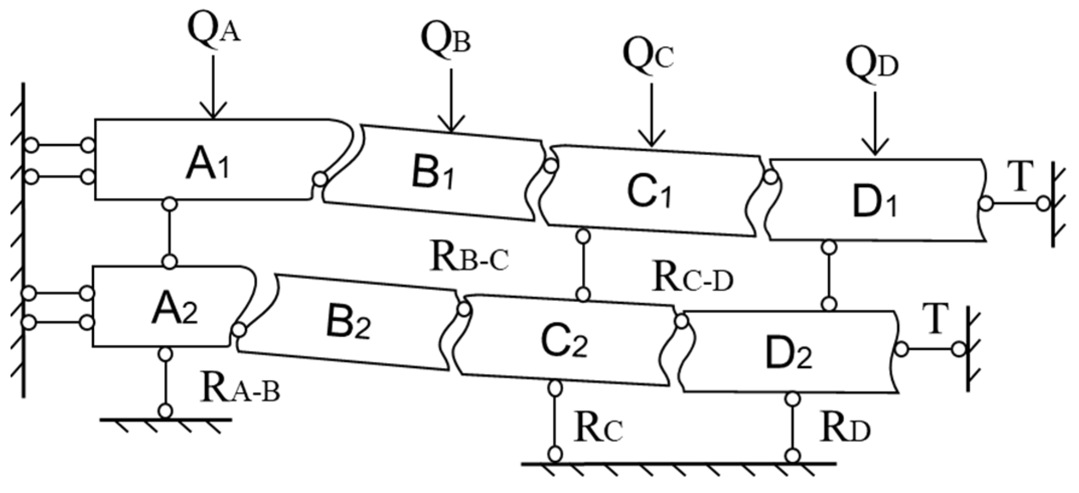
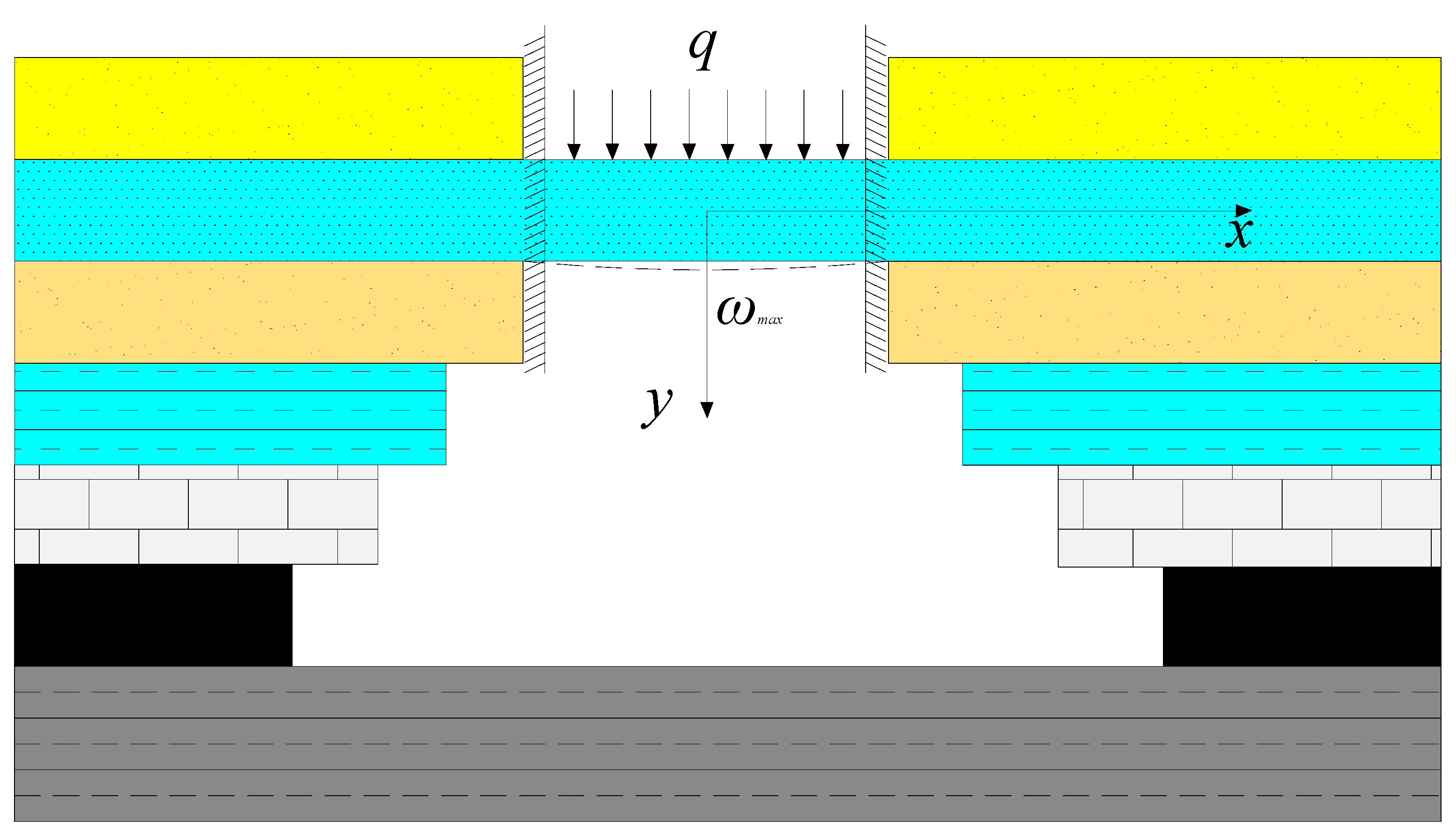
(1) The structure of mining overburden failure in the coal mine was analyzed, and the mechanical model of overburden structure conduction was established. The results suggest that the height of overburden failure is controlled by the lithology of soft strata between adjacent hard strata and the height of free space below.
(2) The bearing stratum breakage distance, maximum deflection and free space of overburden were studied with reference to the overburden histogram data. On this basis, the CFSHS-based height calculation method was proposed, and its applicable conditions were given.
(3) Through the engineering field test, the height of overburden failure in the working face was investigated by means of field measurement and numerical simulation. Moreover, the results obtained through the CFSHS-based height calculation method, numerical simulation and field measurement were comparatively analyzed. The comparison verified accuracy of the CFSHS-based height calculation method.


 ,
, 


