Article

Fuzzy Hysteresis Current Controller for Power Quality Enhancement in Renewable Energy Integrated Clusters

by
Yellapragada Venkata Pavan Kumar
1,*,
Sivakavi Naga Venkata Bramareswara Rao
2,
Kottala Padma
3,
Challa Pradeep Reddy
4,
Darsy John Pradeep
1,
Aymen Flah
5,
Habib Kraiem
6,*,
Michał Jasiński
7 and
Srete Nikolovski
8
1
School of Electronics Engineering, VIT-AP University, Amaravati 522237, Andhra Pradesh, India
2
Department of Electrical and Electronics Engineering, Sir C. R. Reddy College of Engineering, Eluru 534007, Andhra Pradesh, India
3
Department of Electrical Engineering, Andhra University College of Engineering (A), Visakhapatnam 530003, Andhra Pradesh, India
4
School of Computer Science and Engineering, VIT-AP University, Amaravati 522237, Andhra Pradesh, India
5
Energy Processes Environment and Electrical Systems Unit, National Engineering School of Gabes, University of Gabes, Gabes 6029, Tunisia
6
Department of Electrical Engineering, College of Engineering, Northern Border University, Arar 73222, Saudi Arabia
7
Faculty of Electrical Engineering, Wroclaw University of Science and Technology, 50-370 Wroclaw, Poland
8
Power Engineering Department, Faculty of Electrical Engineering, Computer Science and Information Technology, University of Osijek, 31000 Osijek, Croatia
*
Authors to whom correspondence should be addressed.
Sustainability 2022, 14(8), 4851; https://doi.org/10.3390/su14084851
Submission received: 18 March 2022 / Revised: 14 April 2022 / Accepted: 15 April 2022 / Published: 18 April 2022
(This article belongs to the Section Resources and Sustainable Utilization)

Abstract

:
Steady increase in electricity consumption, fossil fuel depletion, higher erection times of conventional plants, etc., are encouraging the use of more and more onsite renewable energy. However, due to the dynamic changes in environmental factors as well as the customer load, renewable energy generation is facing issues with reliability and quality of the supply. As a solution to all these factors, renewable energy integrated cluster microgrids are being formed globally in urban communities. However, their effectiveness in generating quality power depends on the power electronic converters that are used as an integral part of the microgrids. Thus, this paper proposes the “Fuzzy Hysteresis Current Controller (FHCC)-based Inverter” for improving the power quality in renewable energy integrated cluster microgrids that are operated either in grid-connected or autonomous mode. Here, the inverter is controlled through a fuzzy logic-based hysteresis current control loop, thereby achieving superior performance. System modelling and simulations are done using MATLAB/Simulink®. The performance analysis of the proposed and conventional inverter configurations is done by computing various power quality indices, namely voltage characteristics (swell, sag, and imbalance), frequency characteristics (deviations), and total harmonic distortion. The results reveal that the proposed FHCC-based inverter achieves a better quality of power than the traditional ST-PWM-based multilevel inverter in terms of IEEE/IEC/EN global standards for renewable energy integrated cluster microgrids application.

1. Introduction

Energy is a key component of any country’s economic development. In the twenty-first century, people in both urban and rural areas around the world have higher and more sophisticated demands for their quality of life. Urbanization is expected to account for 70% of the world population by 2050, resulting in huge use of existing energy sources [1,2]. Therefore, moving towards sustainable cities is a political and significant objective for many countries given population expansion and recurrent energy crises [3]. Green energy is to be extracted from accessible renewable energy sources while keeping diverse customer demands and environmental issues in mind [4]. As a result, the inspiration for DG-based microgrids has been in the works for several years. Originally, these microgrids were designed to give power to places that have limited access to the electricity. Microgrids are designed to operate in both autonomous and grid-connected modes. With the increased penetration of DGs into the distribution system, several power quality issues, such as voltage swells/sags, voltage waveform shape, voltage flickers, frequency deviations, and total harmonic distortion (THD), are emerging on both the customer and grid sides, particularly when the microgrid is connected to the utility grid [5]. For improving the power quality of microgrids, researchers have created different power devices, such as the “Dynamic Voltage Restorer (DVR)”, “Automatic Voltage Regulator (AVR)”, “Distributed Static Compensator (D-STATCOM)”, and “Unified Power Quality Controller (UPQC)”. To address the aforementioned power quality issues, research is primarily focused on three aspects: (1) inverter topologies controlled by modern modulation techniques, (2) alternative conversion methods to replace power electronic inverters, and (3) taking uncertainty into account while designing storage units for energy management. The following is a summary of the state-of-the-art literature on increasing the power quality of distribution power systems.
In [6], the authors proposed the model predictive control methodology to maintain the power quality of microgrids, which regulates the microgrids’ power converters to meet the criteria. The control algorithm is designed to function with the following microgrids: connected to the grid, islanded, and interconnected. To avoid power quality degradation, a hybrid differential evolution optimization and artificial neural network is utilized to restore system voltage and frequency while considering a wide variety of disturbances [7]. Reference [8] reviewed different control mechanisms for improving power quality in microgrid systems that have been studied and addressed. The same is also expanded to address various filters, power quality compensators, and optimization strategies for improving power quality in microgrids. In [9], the authors discussed the D-STATCOM (Distribution Static Synchronous Compensator), which is used as an inverter-based power quality conditioner to improve power quality in distribution networks. A nonlinear and resilient fuzzy-PI controller is suggested for controlling D-direct STATCOM’s and quadrature axis currents. In addition, the authors presented how the D-fuzzy STATCOM’s logic controls and increases the damping of a power system. Later, in [10], the authors discussed how distributed FACTS in smart grids with renewable energy sources play a vital role in optimizing the power factor, energy utilization, upgrading power quality, assuring effective energy consumption, and energy management. The authors also reviewed FACTS technology tools and applications for improving power quality and maximizing the use of renewable energy systems. In [11], the authors used a chopper, an inverter, and a typical PI controller to improve the power quality of a fuel cell connected to the power network. Two PI controllers are used; each one was tuned using one of the three contemporary evolutionary computing techniques, namely Harmony Search (HS), Modified Flower Pollination Algorithm (MFPA), and Electromagnetic Field Optimization (EFO). A unique artificial neural network based control solution was proposed to minimize the influence of voltage deviation, sag/swell, unbalancing, frequency, total harmonic distortion, and power factor following IEEE/IEC standards [12].
Moreover, in [13], a comprehensive survey of power quality enhancement devices was conducted with a focus on auxiliary services provided by multi-functional DGs. A literature review of the microgrid concept, testbeds, and related control approaches was also conducted. Although certain DGs were used to increase the supply quality, these applications were not designated as multi-functional DGs. In [14], the authors proposed a simple modular cascaded multilevel inverter design with modified unipolar shifted carrier pulse width modulation for microgrids. Multiple power quality indices under dynamic and non-linear loading situations were used to assess the performance of the suggested topology. In [15], the impact of power quality in a freestanding microgrid system (comprising solar, wind, and fuel cell-based DGs) in the presence of a shunt active power filter is explored. Traditional synchronous reference frame and modified synchronous reference frame techniques for reference current generation, and proportional-integral controllers, fuzzy logic controllers for DC-link capacitor voltage regulation, were used. Moreover, a basic hysteresis band current controller technique was used for inverter switching pulse generation. Further, in [16], the authors proposed an improved DPCC for enhancing power quality in a multi-microgrid system in its islanded and interconnected mode of operation. Later, the analysis of a proportional resonant (PR) controller and a selective harmonic compensator (SHC) for a standalone distributed generation inverter is presented. In addition, they proposed and developed an improved triple-action controller (TAC) design. To produce seamless sinusoidal voltage, the suggested TAC consists of a conventional PR, SHC, and a feed-forward current controller [17]. Moreover, in [18], the authors introduced a revolutionary “smart branch” that compensates for diverse power quality disruptions. This contains a series transformer whose secondary impedance is regulated indirectly by voltage injection. This “smart branch” can be regulated adaptively. It is flexible and uses a finite control set-model predictive controller. In [19], the authors provided a wavelet-fuzzy power quality diagnosis approach for evaluating the power quality impact of steady-state (stationary) events in AC microgrids while taking power level penetration into account. The suggested method uses wavelet packet-based signal processing to compute the root mean square and steady-state power quality indices of observed voltages and currents, resulting in accurate findings even in the presence of transient disturbances.
In addition to inverter topologies, certain optimization strategies for sending quality power to the consumer’s side were considered in this literature. In this regard, the authors in [20] proposed an improved current control strategy for a multilayer converter. In online harmonic compensation applications in microgrids, the control method will overcome earlier control systems’ inefficiency in tracking harmonic current. This control method works with multi-functional DG converters that are grid-connected. The coefficients of proportional plus integral controllers and filter parameters of photovoltaic fed distributed static compensators were optimized using a new optimization technique called JAYA. It is unaffected by algorithm-specific control parameters. It overcomes other people’s restrictions in terms of achieving global optima with less computational effort, as discussed in [21]. Later, in [22], the authors examined several power quality parameters in off-grid systems and proposed three evaluation criteria for estimating the performance of a novel forecasting model that incorporates all of the power quality characteristics. These standards are based on standard statistical evaluations of computer models in the field of machine learning.
The work cited above mainly focuses on power quality issues in a single microgrid that is either autonomous or grid-connected, and solutions to interoperable multi-microgrid systems are very limited. Furthermore, the majority of these solutions did not consider all aspects of the power quality issue. Further, the constant growth of regulations governing how energy is created and consumed necessitates the continuing search for innovative and effective solutions. In light of all of these considerations, this paper:
Proposes the idea of interoperating many adjacent microgrids in an urban energy community to form a renewable-energy-based microgrid cluster. This increases the energy availability, thereby improving the power supply reliability by allowing the cluster to manage its own energy requirement rather than relying on the utility grid;
Proposes a new inverter control mechanism, namely “Fuzzy Hysteresis Current Controller-based Pulse Width Modulation (FHCC-PWM)”, which improves the power supply quality. The proposed fuzzy logic improves the control loop ability to regulate the system under variety of operating conditions.
Based on this objective, the rest of the paper is organized as follows: Section 2 describes the system of cluster microgrids with a description of conventional and proposed inverters, their other constituents, and various performance measures. Section 3 describes the concept and implementation of the proposed FHCC. Section 4 provides the results and their corresponding discussion, followed by conclusions in Section 5.

2. Description of the Components Present in Cluster Microgrids

The general architecture of the cluster microgrid system under consideration is depicted in Figure 1, which is made up of four separate green buildings with varied load profiles: residential, software, academic institute, and manufacturing enterprises. Each building is referred to as a single microgrid and is connected to locally available renewable energy sources, such as photovoltaics, wind turbines, and fuel cells, as well as storage batteries, DC/DC converters [11,14,23], power electronic-based inverters, and local building loads (Appendix A).
Microgrid 1 (residential building) consists of a solar photovoltaics and battery storage system with a generation capacity of 4.5 kW to supply a local baseload of 40 kVA. Microgrid 2 (software building) consists of wind sources and fuel cells as the energy sources with the generation capacity of 2.5 kW to supply the local building loads of 38.5 kVA. Microgrid 3 (academic institute building) consists of solar photovoltaics, wind sources as the energy sources, and a battery as a storage system with a generation capacity of 4.25 kW to supply the local building loads of 57 kVA. Microgrid 4 (manufacturing enterprises building) consists of solar photovoltaics, fuel cells as the energy sources, and also consists of a battery as a storage system with a generation capacity of 4 kW to supply the local building loads of 60 kVA. A DC bus is modelled in this work to supply 500 V DC voltage to the inverter to produce a corresponding AC voltage of 415 V at the output. The proposed microgrid cluster requires an energy management and control unit (EMCU) to make the power transactions with adjacent microgrids/utility grid during power excess/deficit conditions. In this cluster, four microgrids are interconnected with interoperability, where each microgrid in the cluster is associated with a local agent controller that communicates with neighborhood microgrids and also with the utility grid for energy transactions through EMCU.

2.1. Description of ST-PWM Based Multilevel Inverter

The power electronic inverter is crucial in renewable energy-based power systems. In general, two-level inverters are widely used in many industrial applications, such as traction drives, renewable energy integration, and also in high-voltage DC transmission. However, these two-level inverters are facing some serious issues, such as high switching frequencies, high switching losses, and also non-availability of high power devices. These issues are overcome by using multilevel inverters. Hence, the RES-generated DC power is fed to AC loads via a traditional multi-level inverter, which is connected to the point of common coupling (PCC). In this work, a three-phase, five-level diode clamped inverter is modelled for the analysis of an interconnected microgrid clustering system considered for the study. It consists of four DC-link capacitors and 28 switching devices that operate at a switching frequency of 100 kHz [23]. The main function of clamping diodes is to obtain clamped voltage with different DC voltage levels. For creating required switching pulses, the inverter in a cluster microgrid system is first developed using sinusoidal triangular pulse width modulation (ST-PWM) control. The configuration, generation of gate pulses for one leg, and the output voltage per phase of the ST-PWM-based multilevel inverter are shown in Figure 2. Similarly, the switching logic for its operation is given in Table 1.

2.2. Description of Proposed FHCC Based Inverter

The multi-level inverter is sufficient for improving power quality, but as we get to higher levels, switching losses grow, the control structure becomes more complex, and the system becomes bulky and more expensive. All of these issues are reduced with the suggested inverter, which is controlled by machine learning technique, namely “Fuzzy Logic-based Hysteresis Current Controller (FHCC)”, to control the multi-level inverter for improved power quality. The proposed inverter is designed as a current-controlled voltage source converter, reducing the need for clamping diodes and capacitors. A detailed description of this suggested controller is explained in Section 3.

2.3. Description of Energy Management Control Unit (EMCU)

An energy management control unit (EMCU) is an information system on a software platform that supports the functionality of providing low-cost generation, transmission, and distribution of electrical energy, according to the international standard IEC 61970. In microgrids, energy management is a computer-based control strategy that ensures the system’s best performance. A microgrid must optimize the use of renewable energy sources in a variety of ways. The EMCU components that carry out decision-making procedures include machine interfaces and SCADA (Supervisory Control and Data Acquisition Systems). Therefore, in this article, an effective EMCU called two-layer energy management control is adopted [23], which is incorporated in the proposed cluster microgrid system for managing the resources connected in all microgrids. This makes smooth energy transactions and also maintains grid frequencies under various loading conditions.

2.4. Performance Issues and Measures

With the high penetration of DG sources in the distribution grid, power electronic-based inverters play a very important role. These power electronic systems have nonlinear characteristics. Due to this non-linearity, several power quality issues appear on the grid side and also at the consumer premises. Therefore, in grid-connected renewable energy-based microgrids, the major challenge is to keep the power quality indices in acceptable ranges, i.e., voltage characteristics such as sag/swell should be in the range of 40% as per IEC61000-4-11, voltage imbalances should be in the range of ±3% as per IEEE 1159.3 and EN 50160, frequency deviations are in the range ±2% as per IEC 61727 and IEC 61000-2-2, and harmonic distortion is in the range of 5% as per IEEE 1547.1 and IEEE-519.
Voltage sag/swell: Root mean square (RMS) value of voltage ( V R M S x ) is calculated by squaring all the sampled voltages and is averaged over a window with a duration of one cycle at the sampling instant x given in Equation (1). Voltage sag and swell are the drop and rise that are observed in the RMS value of the voltage that occurs due to sudden rise and fall of the load, respectively.
Voltage imbalance: It is defined as the ratio of negative sequence voltage to positive sequence voltage expressed in terms of the percentage given in Equation (2).
Frequency variations: The load frequency is to be continuously monitored and maintained close to 50 Hz with the penetration of DG sources in microgrids and is given in Equation (3).
Total harmonic distortion (THD): THD is the measure for the level of distortion (harmonic) present in a three-phase power system. It is calculated by measuring the ratio between the amplitudes (RMS value) of a set of total higher-frequency components with respect to harmonics and the value at fundamental frequency components given in Equations (4) and (5).
V R M S x = 1 y k = 1 + i y i V k 2  
V o l t a g e   i m b a l a n c e   ( % ) = v o l t a g e v e s e q v o l t a g e + v e s e q × 100
Δ f = ( Δ P M G 1 + Δ P M G 2 + Δ P M G 3 + Δ P M G 4 ) ρ
T H D v o l t a g e = i = 2 ( V i r m s ) 2 V f u n d r m s
T H D c u r r e n t = i = 2 ( I i r m s ) 2 I f u n d r m s
where y is the number of samples per cycle, Vk is the recorded voltage waveform sample, ρ is the frequency droop coefficient of cluster microgrids, and Δ P M G i (for I = 1, 2, 3, 4…) is the real power change in the ith microgrid; V i r m s and I i r m s are the voltage and current components corresponding to nth harmonic, respectively. Similarly, the voltage and current components with respect to the fundamental frequency of ith microgrid are V f u n d r m s and I f u n d r m s .

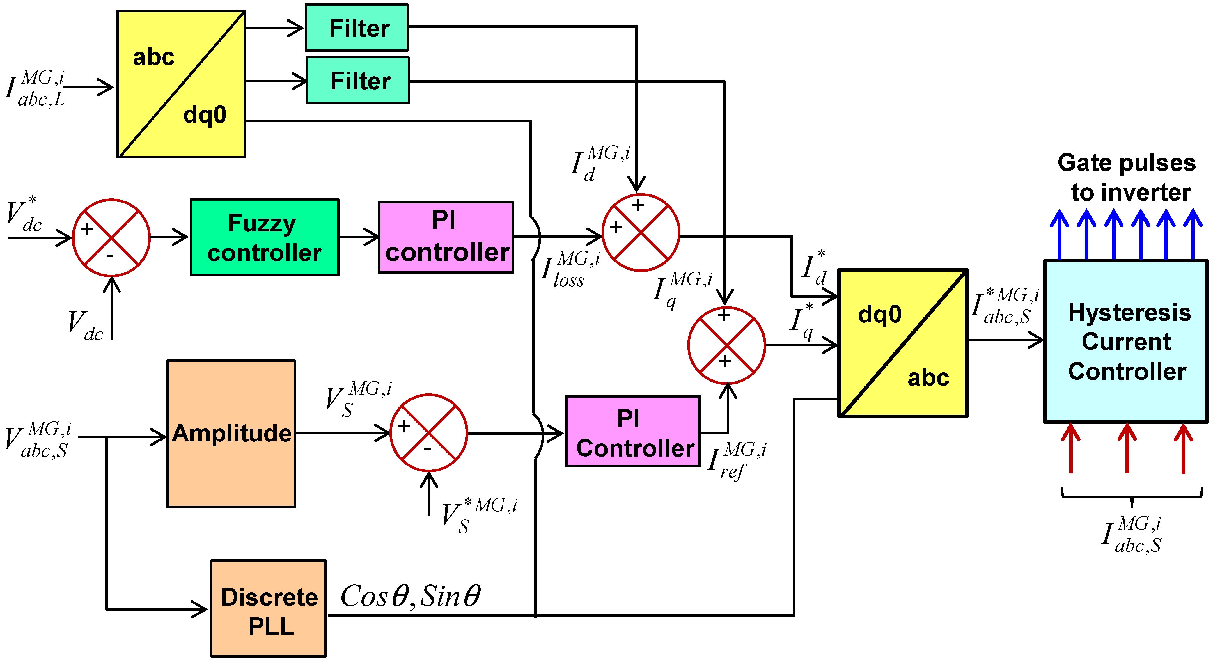
3. Proposed Fuzzy Hysteresis Current Controller (FHCC)

The proposed control circuit for producing switching pulses for the inverter is shown in Figure 3. The philosophy involved is explained in the following two subsections. Section 3.1 examines the generation of reference current using SRF theory and fuzzy logic, while Section 3.2 discusses the development of switching gate pulses using a hysteresis current controller, which generates gate pulses to the inverter of the ith microgrid.

3.1. Reference (Source) Current Generation

The reference current is obtained from the voltage (source) and current (load) of ith microgrid. The set of voltages and currents are transformed α β ο frame using Equations (6) and (7) [15]. The d-q (direct and quadrature) reference frame is obtained from the angle with respect to α β ο frame.
[ ν ο M G , i ν α M G , i ν β M G , i ] = 2 3 [ 1 2 1 2 1 2 1 1 2 1 2 0 3 2 3 2 ] [ ν a M G , i ν b M G , i ν c M G , i ]
[ I ο M G , i I α M G , i I β M G , i ] = 2 3 [ 1 2 1 2 1 2 1 1 2 1 2 0 3 2 3 2 ] [ I a M G , i I b M G , i I c M G , i ]
Here, I a b c M G , i and v a b c M G , i are the source currents and voltages with respect to a b c frame, and I α β ο M G , i , v α β ο M G , i are the source currents and voltages with respect to α β ο frame. The transformation of α β ο frame to d q o frame is given in Equation (8).
[ I ο M G , i I d M G , i I q M G , i ] = [ 1 0 0 0 cos θ sin θ 0 sin θ cos θ ] [ I ο M G , i I α M G , i I β M G , i ]
The reference current with respect to d-axis ( I d * ) was obtained as given in Equation (9).
I d * = I d M G , i + I l o s s M G , i
where I d M G , i is the d-axis current, and the loss component value at p t h sampling instant ( I l o s s ( p ) M G , i ) for meeting the losses in ith microgrid is obtained as given in Equation (10).
I l o s s ( p ) M G , i = I l o s s ( p 1 ) M G , i + m p d [ ( V d c * V d c ) p ( V d c * V d c ) ( p 1 ) ] + m i d ( V d c * V d c ) p
where, m p d , m i d are PI controller gains and are tuned by fuzzy logic rules. The real power supplied by the source should be equal to the real power demand of the load in the steady-state plus a modest amount to compensate for filter losses. As a result, the DC capacitor voltage can be kept constant. In this study, a fuzzy controller is introduced to the d-axis in the d-q frame to effectively manage the active current component to keep the DC link voltage constant.
The planned fuzzy controller will set the PI controller’s parameters in such a way that it is utilized to manage a small amount of active current, which is subsequently regulated by the current controller to keep the DC-link capacitor voltage constant. Similarly, the reference current with respect to q-axis ( I q * ) is obtained as Equation (11).
I q * = I q M G , i + I q r e f M G , i
Here, I q M G , i is the q-axis current, and I q r e f M G , i is the output component produced by the PI controller. The magnitude of the terminal voltage of ith microgrid at PCC is calculated as given in Equation (12), and the q axis reference current at p t h sampling instant of ith microgrid is given in Equation (13).
V t M G , i = ( 2 3 ( V a s 2 + V b s 2 + V c s 2 ) ) 1 / 2
I q r e f ( p ) M G , i = I q r e f ( p 1 ) M G , i + m p q { ( V t e * M G , i ) p ( V t e * M G , i ) ( p 1 ) } + m i q ( V t e M G , i ) p
where I q r e f ( p ) M G , i is the q-axis current at p t h sampling instant; V t e ( p ) M G , i = ( V t * M G , i V t M G , i ) is terminal voltage amplitude of ith microgrid at p t h sampling instant obtained by taking the difference between measured value ( V t M G , i ) and reference value ( V t * M G , i ); and m p q ,   m i q are PI controller gains. The reference current can be obtained as given in Equation (14).
[ I ο s * M G , i I α s * M G , i I β s * M G , i ] = [ 1 0 0 0 cos θ sin θ 0 sin θ cos θ ] [ 0 I d * M G , i I q * M G , i ]
By applying the reverse transformation to the above current vector, we then obtain the reference source vector as given in Equation (15).
[ I a s * M G , i I b s * M G , i I c s * M G , i ] = 2 3 [ 0 1 0 0 1 2 3 2 0 1 2 3 2 ] [ I ο s * M G , i I α s * M G , i I β s * M G , i ]
where I a b c , s * M G , i and I α β ο , s * M G , i are the reference source currents with respect to a b c and α β ο frames. The scheme of fuzzy logic (fuzzification) is explained as follows.
Scheme of fuzzy logic: In this scheme, the fuzzy controller of the proposed inverter is implemented by considering and evaluating some linguistic rules. The internal process of fuzzy controller is explained as follows. The input error value is calculated by taking the difference between the reference voltage (V*dc) and sensed voltage (Vdc). Here, both input signals, i.e., e ( n ) and Δ e ( n ) , are numerical variables and are transformed to linguistic variables by considering the following fuzzy sets as given. The characterization of fuzzy logic is as follows:
  • Consists of seven fuzzy sets (N-3, N-2, N-1, E0, P1, P2, and P3);
  • For simplicity, the triangular membership function is considered;
  • Mamdani fuzzy inference mechanism is used;
  • “Centroid method” is used for defuzzification.
Fuzzification: In this process, instead of numerical values, fuzzy uses linguistic variables. In the system, the error signal can be assigned to negative large (N-3), negative medium (N-2), negative small (N-1), extreme zero (E0), positive small (P1), positive medium (P2), and positive large (P3). This process converts numerical variables to linguistic variables (fuzzy numbers), and the surface plot of the fuzzy logic controller is shown in Figure 4.
Rule elevation: Basic operations of fuzzy logic are needed to evaluate fuzzy set rules shown in Figure 5, which are obtained by considering “union”, “intersection”, and “complement” functions. Considering two fuzzy sets ( M ¯ and N ¯ ), the universe A and the following Equations (16)–(18) are the basic relations performed on fuzzy sets.
Union   operation μ M ¯ N ¯ ( x ) = μ M ¯ μ N ¯ , x A
Intersection   operation μ M ¯ N ¯ ( x ) = μ M ¯ μ N ¯ , x A
Complement   operation μ M ¯ = 1 μ M ¯ ( x ) , x A
Process of getting defuzzified output: With the process of defuzzification, a fuzzy set is converted to its crispest version. The mathematical expression for obtaining defuzzified output x * is as given in Equation (19).
x * = μ M ¯ ( x ) · x · d x μ M ¯ ( x ) · x
Rule matrix: It is used to represent fuzzy sets and operators in the form of conditional statements. In this fuzzy logic controller, a total of 49 rules are used, and the list is given in Table 2. The fuzzy membership functions are shown in Figure 6.

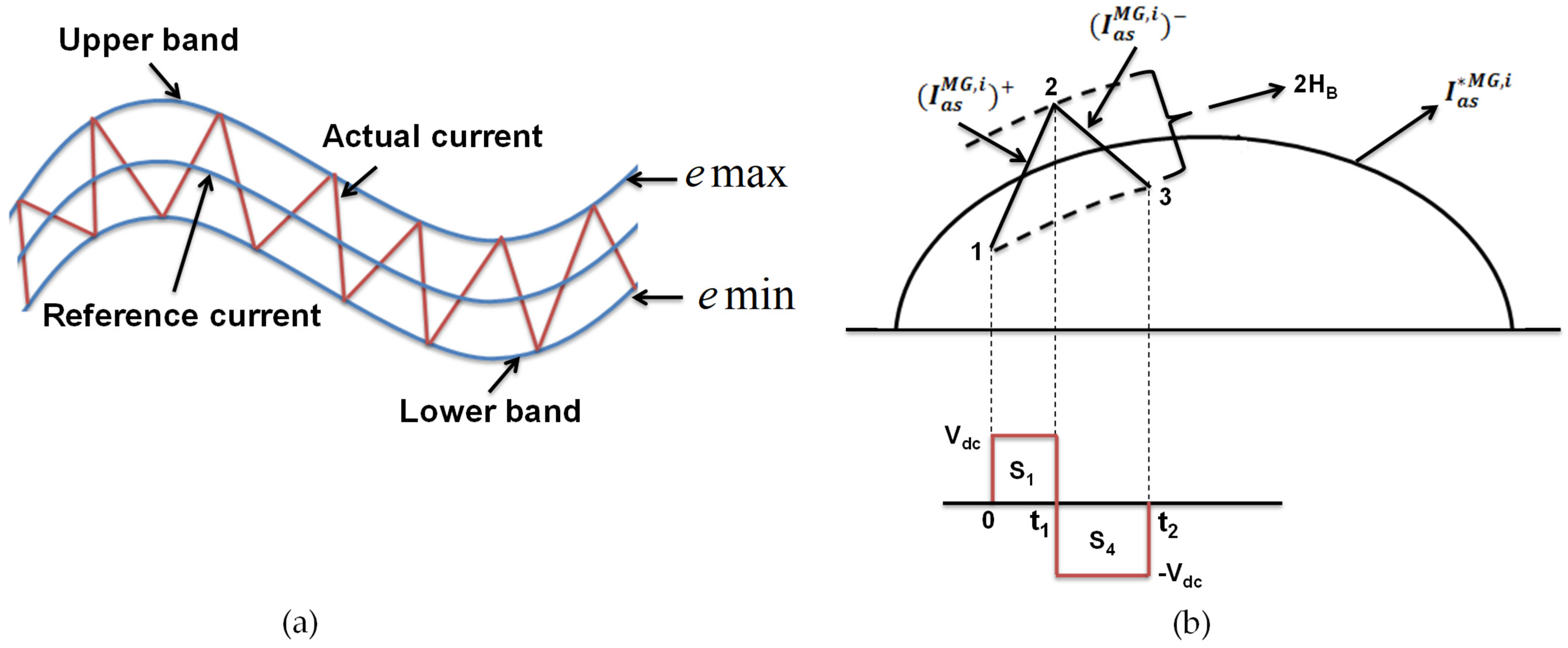
3.2. Gate Pulses Generation from Hysteresis Current Controller

The hysteresis current controller can be implemented to generate the switching pulses to the inverter to obtain a faster response and is connected in each phase independently [24,25]. The conventional hysteresis current controller used in this work is shown in Figure 7. The actual current I a c t M G , i ( t ) is compared with the reference current I r e f * M G , i ( t ) of ith microgrid, and the resultant error current signal is passed through the hysteresis current controller to produce the switching gate signals to the proposed inverter. The logic behind the generation of switching pulses of the inverter of the ith microgrid is given as follows:
(1)
If I a c t M G , i ( t ) < ( I r e f * M G , i ( t ) H B ) , then inverter upper switch is OFF, and lower switch is ON for leg corresponding to phase A of the ith microgrid;
(2)
If I a c t M G , i ( t ) > ( I r e f * M G , i ( t ) + H B ) , then inverter upper switch is ON, and lower switch is OFF for leg corresponding to phase A of the ith microgrid.
If the error signal in phase A crosses the upper band limit of hysteresis, then the upper switch of the inverter corresponding to phase A is OFF, and the lower switch is ON. Due to this action, current starts decaying. If the error signal in phase A crosses the hysteresis lower band limit, then the lower switch of the inverter arm corresponding to phase A is turned OFF, and the upper switch is turned ON. As a result, the current again returns into the hysteresis band. Similarly, the logic for the remaining two phases can be determined.
The geometry of the hysteresis controller is shown in Figure 7. From this, the rising edge currents and falling edge currents are computed as given in Equation (20) and Equation (21), respectively, from which the hysteresis band (HB) can be calculated as in Equation (22). This is obtained by considering switching intervals t1 and t2 as shown in Figure 7, where La is phase inductance, ( I a s M G , i ) + and ( I a s M G , i ) are rising and falling segments of current. From Figure 7, the following relations can be written as given in Equations (23) and (24):
d ( I a s M G , i ) + d t = 1 L a ( V d c V a s M G , i )
d ( I a s M G , i ) d t = 1 L a ( V d c + V a s M G , i )
t 1 · d ( I a s M G , i ) + d t t 1 · d ( I a s * M G , i ) d t = 2 H B
t 2 · d ( I a s M G , i ) d t t 2 · d ( I a s * M G , i ) d t = 2 H B
t 1 + t 2 = τ c = 1 f c
Here, t1 and t2 are switching intervals, and fc is the modulation frequency. By adding Equations (22) and (23) and substituting Equation (24), we arrive at Equation (25). Similarly, by substituting Equations (20)–(22) in Equation (25) and after simplification, we obtain Equation (26).
t 1 · d ( I a s M G , i ) + d t + t 2 · d ( I a s M G , i ) d t ( t 1 + t 2 ) d ( I a s * M G , i ) d t = 0
t 1 t 2 = L a V d c · f c ( V a s M G , i L a + d I a s * M G , i d t )
By subtracting Equation (23) from Equation (22), we derive Equation (27), and by substituting Equations (20), (21), and (24) in Equation (27), after simplification, we obtain Equation (28).
t 1 d ( I a s M G , i ) + d t t 2 d ( I a s M G , i ) d t ( t 1 t 2 ) d ( I a s * M G , i ) d t = 4 H B
V d c f c · L a ( t 1 t 2 ) ( V a s M G , i L a + d I a s * M G , i d t ) = 4 H B
Substitute Equation (26) in Equation (27), and on simplification, we arrive at Equations (29) and (30). The hysteresis band (HB) obtained in Equation (30) can be modulated at different instants of frequency to obtain the required gate pulses to the inverter of an ith microgrid.
V d c f c · L a L a V d c · f c ( V a s M G , i L a + d I a s * M g , i d t ) = 4 H B
H B = { V d c 4 f c L a ( 1 L a 2 V d c 2 [ V a s M G , i L a + d I a s * M G , i d t ] 2 ) }

4. Results and Discussion

The power quality using the proposed FHCC-based inverter for urban community microgrids is investigated using characteristics such as voltage swell/sag, voltage imbalance, frequency deviations, and total harmonic distortion (THD). All parameters for the proposed FHCC-based inverter for cluster microgrids have been determined and compared to the conventional inverters for cluster microgrids following IEEE/IEC standards [26,27,28,29,30,31,32,33,34,35]. Two conventional inverters are considered for the study: one is a traditional ST-PWM-based inverter [14], and the second is an FSV-PWM-based inverter [36]. MATLAB/Simulink 2021, a software with a runtime version of 9.1 for Windows 64 bit, is used to model the planned interconnected microgrid system as well as individual microgrids that are connected to the utility grid.

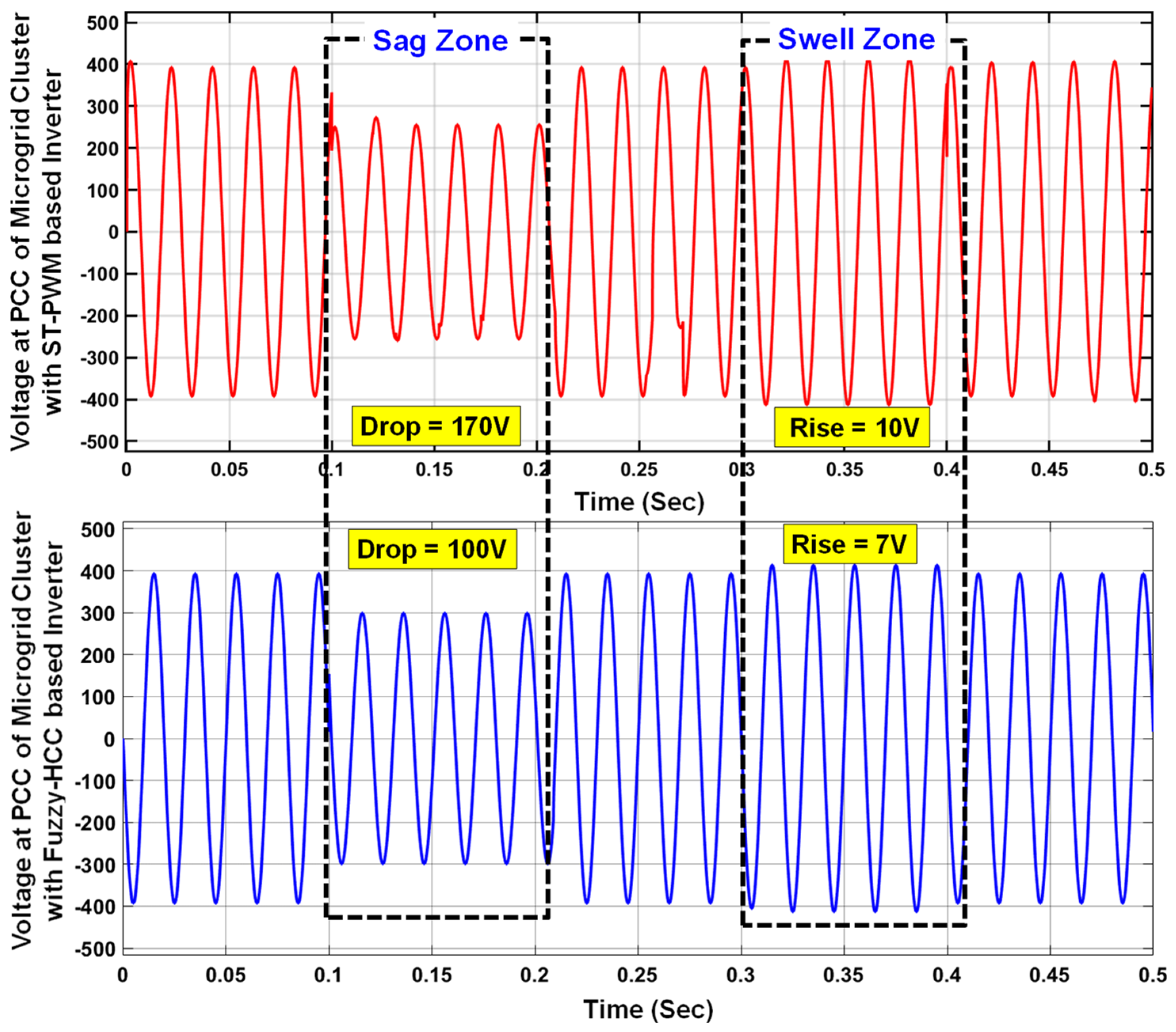
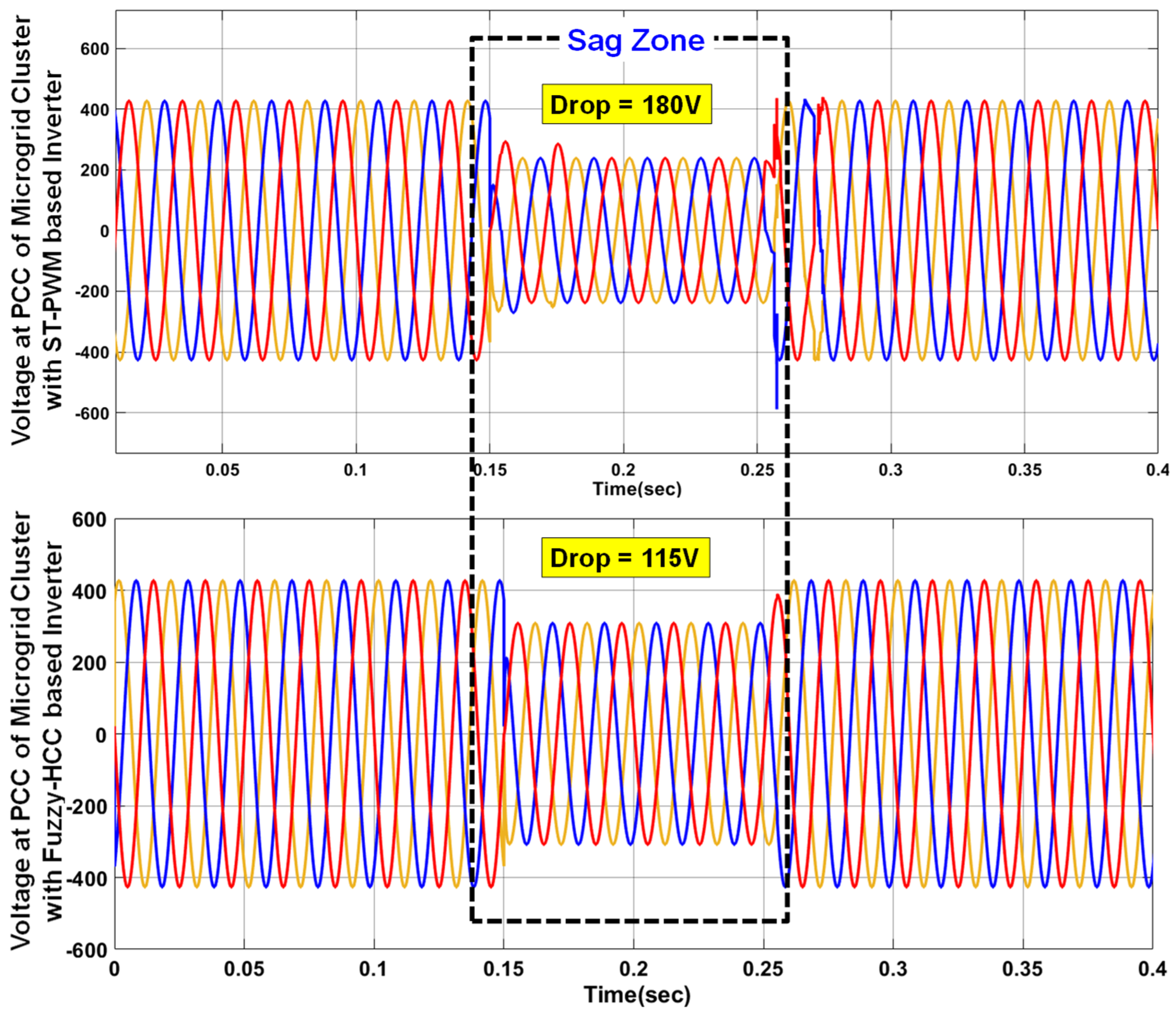
4.1. Analysis of Voltage Characteristics

A pure sinusoidal voltage waveform must be maintained in the microgrid cluster system; otherwise, a distorted waveform will result in unequal voltage distribution. A test load, i.e., a high impedance load, contains more reactance, e.g., 50 kW + j200 kVAR, is applied to the system considered for study to observe the voltage waveform shape. Figure 8 shows the shape of the voltage waveform produced at the PCC of cluster microgrids. From the result, it is observed that the proposed FHCC-based inverter produces a pure sinusoidal waveform when compared with the conventional ST-PWM-based inverter, which contains small distortions in its voltage waveform.
Furthermore, voltage sag occurs when the current flowing through the impedance (source) changes abruptly, and sudden application of load or faults drains large amounts of source currents, lowering the voltage. When there is a voltage swell, removing the load quickly causes the source currents to drop, causing the voltage to rise. To observe the voltage sag, apply a single line to ground (SLG) fault near to the PCC of cluster microgrids in phase A from 0.1 s to 0.2 s with a base load of 275 kW. The Simulink results with ST-PWM- and FHCC-based inverters are shown in Figure 9.
From results, it is observed that when SLG fault is applied at 0.1 s, the voltage is dropped to 230 V in the case when THE ST-PWM-based inverter is used, and the voltage is dropped to 300 V in the case when the proposed FHCC-based inverter is used. Similarly, the sag in the case of THE ST-PWM-based inverter is observed as 42.5%, and for the FHCC-based inverter, it is observed as 25%. Further, the swell in cluster microgrids is obtained by disconnecting a portion of baseload, e.g., 75% of 275 kW from 0.3 s to 0.4 s. From the results shown in Figure 9, the swell in the cluster microgrids with ST-PWM inverter is 10 V and with the proposed inverter is 7 V. Similarly, arc furnace load is applied from 0.15 s to 0.25 s to observe the sag in cluster microgrids by considering the base load of 250 kW. The corresponding results are as shown in Figure 10, from which it is observed that the sag is 43.37% using an ST-PWM-based inverter, while it is 27.7% with the FHCC-based inverter.
In order to study the voltage imbalances through positive and negative sequence components, inject a load of j30 kVAR (inductive load) in phase A at 0.12 s along with a base load of 275 kW + j50 kVAR and a test load of j35 kVAR. The results are shown in Figure 11, from which it is observed that the voltage imbalance with the ST-PWM-based inverter is 3.06% and with the FHCC-based inverter is 2.86%. Further, the flicker impact on the system voltage was also studied. Flicker is defined as a visual impression caused by a light stimulus whose spectral component distribution changes over time [26,27]. Both the ST-PWM-based inverter and the FHCC-based inverter for cluster microgrids at PCC produce short-term flicker sensations without spectral correction as shown in Figure 12. All the results that were obtained through simulations are consolidated as given in Table 3 along with standard requirements defined by IEEE/IEC/EN.

4.2. Analysis of Frequency Characteristics

When the cluster microgrids are operated in grid-connected/autonomous mode, frequency is a critical parameter that must be monitored and managed continually. To observe the variation in frequency response for large impedance loads, apply a constant impedance of 275 kW + j150 kVAR − j50 kVAR in the cluster microgrids from 0 s to 0.7 s. The results obtained from the simulation are shown in Figure 13. From these results, it is identified that the settling time (0.55 s) obtained with the ST-PWM-based inverter is more when compared with the settling time (0.3 s) obtained with the FHCC-based inverter.
At the same time, to observe the variation in frequency response for large reactive loads, apply a load of 125 kW + j200 kVAR − j175 kVAR in the cluster microgrids and follow the below given testing procedure:
  • Switch the inductive load ON at 0.5 s and OFF at 0.8 s;
  • Switch the capacitive load ON at 1.3 s and OFF at 1.6 s:
  • Observe deviation in case of dynamic loading.
The corresponding simulation results are shown in Figure 14. From this, it is identified that the deviation is less with the FHCC-based inverter when compared with the ST-PWM-based inverter. The summary of quantitative frequency characteristics is mentioned in Table 3.

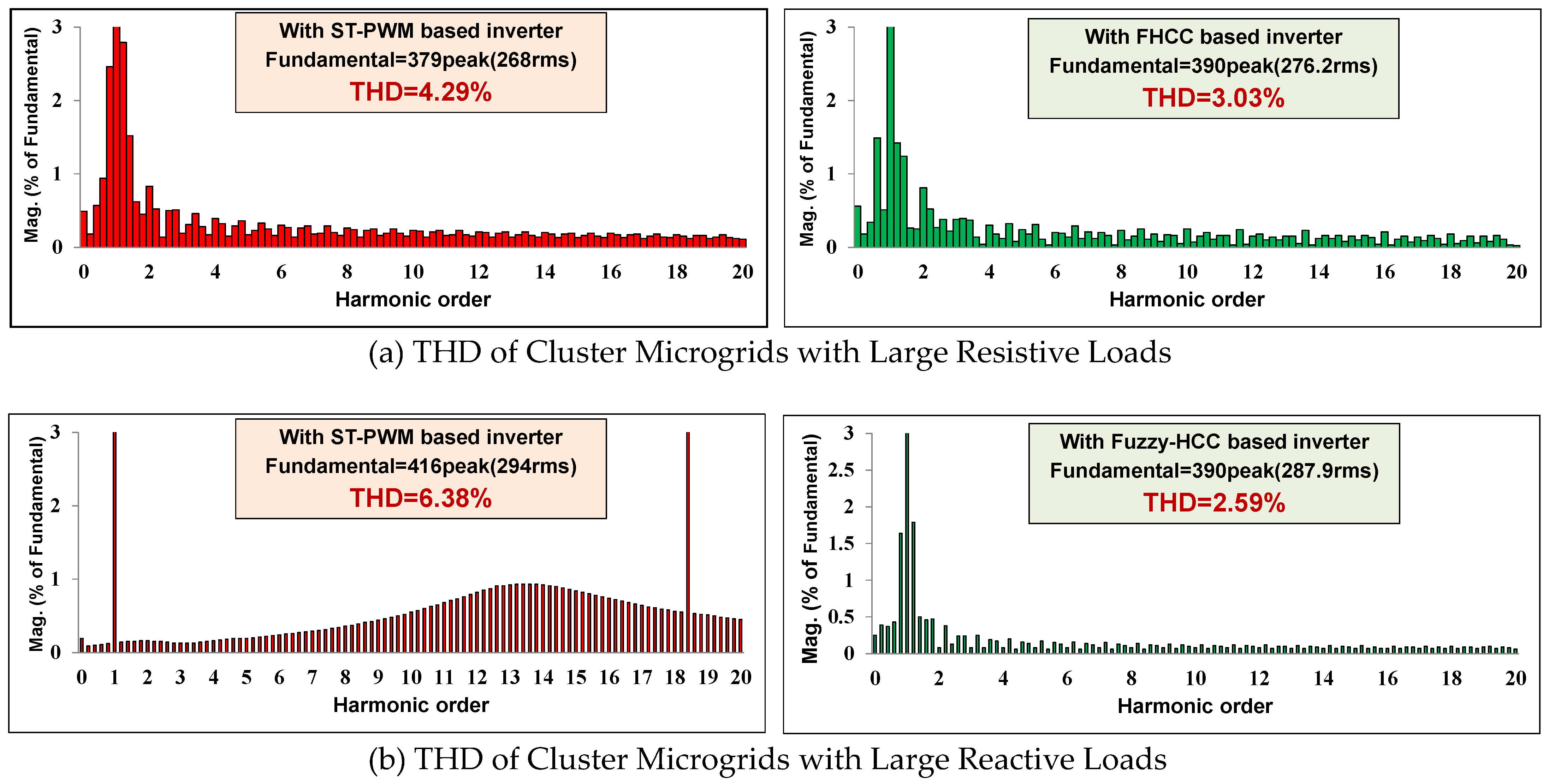
4.3. Analysis of THD

Total harmonic distortion (THD) is caused by nonlinear/high reactive loads in the system. To observe the effect of large resistive load on the system, the loads are injected into the system as follows: First, 250 kW is applied from 0.04 s to 0.1 s; 500 kW is applied from 0.08 s to 0.16 s; and 400 kW is applied from 0.12 s to 0.2 s. Similarly, to observe the effect of large reactive load on the system, the loads are injected into the system as follows: Switch ON j125 kVAR load at 0.12 s, and already connected −j125 kVAR load must be switched OFF at 0.12 s along with the baseload of 275 kW. The simulation results are shown in Figure 15, and the consolidated results are tabulated in Table 3.

5. Conclusions

Thus, to address the issues associated with uncertain renewable energy sources in the distribution grid and concerns with power electronic converters, this paper implements renewable energy integrated clusters that are formed with proposed fuzzy hysteresis current controller (FHCC)-based inverter. The salient merits of this proposed system are described as follows:
The proposed FHCC-based inverter is easy to build, as it does not require any clamping diodes and capacitors when compared to conventional configurations. This further reduces the switching losses.
The proposed inverter employs fuzzy logic, which reduces the complexity in mathematical formulation.
From results, the FHCC-based inverter:
-
Reduces the voltage sag to 25% when compared with conventional ST-PWM-based inverter (42.5%) and recent FSV-PWM-based inverter (29.5%) when the system is subjected to single line-to-ground fault. Similarly, it reduces the voltage sag to 27.7% when compared with conventional ST-PWM-based inverter (43.37%) and recent FSV-PWM-based inverter (38.6%) when subjected to arcing loads;
-
Reduces the voltage swell to 2.5% when compared with conventional ST-PWM-based inverter (4.76%) and recent FSV-PWM-based inverter (2.73%) when subjected to sudden disconnection of major part (75%) of the system load;
-
Reduces the voltage unbalance to 2.46% when compared with conventional ST-PWM-based inverter (3.08%) and recent FSV-PWM-based inverter (2.87%) when subjected to large reactive loads injected into the system;
-
Reduces the settling time of the system to 0.35 s when compared with conventional ST-PWM-based inverter (0.55 s) and recent FSV-PWM-based inverter (0.42 s);
-
Reduces the frequency deviation of the system to 0.3% when compared with conventional ST-PWM-based inverter (1%) and recent FSV-PWM-based inverter (0.45%);
-
Reduces the total harmonic distortion of the system to 3.03% when compared with conventional ST-PWM-based inverter (4.29%) and recent FSV-PWM-based inverter (3.85%) when subjected to large resistive loading. Similarly, it reduces the total harmonic distortion of the system to 2.59% when compared with conventional ST-PWM-based inverter (6.38%) and recent FSV-PWM-based inverter (4.73%) for large reactive loading.
As a result of these findings, the proposed FHCC-based inverter is determined to be the best option for improving power quality in urban community cluster microgrids.

Author Contributions

Conceptualization, Y.V.P.K. and S.N.V.B.R.; data curation, Y.V.P.K., C.P.R., and M.J.; formal analysis, S.N.V.B.R. and A.F.; funding acquisition, Y.V.P.K. and H.K.; methodology, Y.V.P.K. and S.N.; project administration, H.K.; resources, C.P.R.; software, C.P.R.; supervision, Y.V.P.K., K.P. and H.K.; validation, D.J.P.; visualization, D.J.P. and A.F.; writing—original draft, S.N.V.B.R.; writing—review and editing, Y.V.P.K., K.P., M.J. and S.N. All authors have read and agreed to the published version of the manuscript.

Funding

This research was funded by Ministry of Education in Saudi Arabia under grant number (IF_2020_NBU_419) and by Science and Engineering Research Board (SERB) in India under grant number (SRG/2019/000648).

Institutional Review Board Statement

Not applicable.

Informed Consent Statement

Not applicable.

Data Availability Statement

Not applicable.

Acknowledgments

The authors extend their appreciation to the Deputyship for Research and Innovation, Ministry of Education in Saudi Arabia, for funding this research work through the project number (IF_2020_NBU_419). The authors gratefully thank the Prince Faisal bin Khalid bin Sultan Research Chair in Renewable Energy Studies and Applications (PFCRE) at Northern Border University for their support and assistance. In addition, the authors thank Start-up Research Grant (SRG) scheme of the Science and Engineering Research Board (SERB), a statutory body under the Department of Science and Technology (DST), Government of India, for supporting this work under the Project number (SRG/2019/000648).

Conflicts of Interest

The authors declare no conflict of interest.

Nomenclature

MGMicrogrid I d M G , i Direct axis current of ith MG in amps
THDTotal Harmonic Distortion I q M G , i Quadrature axis current of ith MG in amps
DGDistributed Generation I l o s s M G , i Loss component of current in ith MG in amps
PQPower quality I d * Reference source current of d-axis in d-q frame in amps
ρ Frequency Droop coefficient I q * Reference source current of q-axis in d-q frame in amps
fChange in frequency in Hz I a b c , S M G , i Three-phase source current of ith MG in a-b-c frame in amps
V R M S x Voltage (RMS) at a sampling instant x in volts I α β ο , S M G , i Three-phase source current of ith MG in α-β-ο frame in amps
V i r m s Voltage (RMS) at ith MG at nth harmonic in volts I a b c , S * M G , i Three-phase source reference current of ith MG in a-b-c frame in amps
I i r m s Current (RMS) at ith MG at nth harmonic in amps I α β ο , S * M G , i Three-phase source reference current of ith MG in α-β-ο frame in amps
V f u n d r m s Voltage (RMS) at ith MG at fundamental frequency in volts I a c t M G , i ( t ) Actual current of ith MG in amps
I f u n d r m s Current (RMS) at ith MG at fundamental frequency in amps I r e f * M G , i ( t ) Reference current of ith MG in amps
I a b c , L M G , i Three-phase load current of ith MG in ampsHBHysteresis band
V a b c , S M G , i Three-phase voltage at PCC of ith MG in volts ( I a M G , i ) + Raising segment of current in phase A in amps
V d c * Reference DC voltage in volts ( I a M G , i ) Falling segment of current in phase A in amps
V d c Sensed DC voltage in voltsfcModulation frequency in Hz

Appendix A

Specifications of the components used for the simulation:
ParameterTypical Ratings
Irradiance of PV cell(150–1000) kW/m2
Temperature of PV cell(20–45) °C
Electric charge (Q)1.6 × 10⁻¹⁹ Coulombs
Boltzmann’s constant1.3805 × 10−23 J/K
Base power of wind turbine1.1 kVA
Speed of wind10 m/s
Nominal voltage of Ni-cd battery88 Volts
Rated capacity of Ni-cd battery6.5 Ah
Gas constant of fuel cell8314.7
No of cells in stack of fuel cell80
Duty cycle of the boost converter0.76
Switching frequency of the converter100 kHz
Cutoff frequency of low pass filter500 Hz
Transmission line length10 Km
Power of transformer300 kVA
Voltage415 Volts
DC capacitor voltage 680 Volts
K p d 0.19
K i d 6.25
K p q 0.19
K i q 7.5
(1)
Input variable 1 (error)
(2)
Input Variable 2 (Change in error)
(3)
Output variables of fuzzy controller
NB-3: (−1.333 −0.7 −0.3)
NM-2: (−0.726 −0.354 −0.1372)
NM-1: (−0.277 −0.147 0)
EZ0: (−0.1 0 0.1)
PS + 1: (0 0.18 0.38)
PM + 2: (0.18 0.38 0.75)
PB + 3: (0.38 0.75 1.33)

References

  1. Razmjoo, A.; Nezhad, M.M.; Kaigutha, L.G.; Marzband, M.; Mirjalili, S.; Pazhoohesh, M.; Memon, S.; Ehyaei, M.A.; Piras, G. Investigating Smart City Development Based on Green Buildings, Electrical Vehicles and Feasible Indicators. Sustainability 2021, 13, 7808. [Google Scholar] [CrossRef]
  2. Shahidehpour, M.; Li, Z.; Ganji, M. Smart cities for a sustainable urbanization: Illuminating the need for establishing smart urban infrastructures. IEEE Electrif. Mag. 2018, 6, 16–33. [Google Scholar] [CrossRef]
  3. Warneryd, M.; Håkansson, M.; Karltorp, K. Unpacking the complexity of community microgrids: A review of institutions’ roles for development of microgrids. Renew. Sustain. Energy Rev. 2020, 121, 109690. [Google Scholar] [CrossRef]
  4. Rao, S.N.V.B.; Padma, K. A Review on Schemes for Interconnecting Microgrids of Urban Buildings. In Microelectronics, Electromagnetics and Telecommunications; Book chapter; Springer: Berlin/Heidelberg, Germany, 2020; pp. 431–438. [Google Scholar] [CrossRef]
  5. Kakran, S.; Chanana, S. Smart operations of smart grids integrated with distributed generation: A review. Int. J. Renew. Sustain. Energy Rev. 2018, 81, 524–534. [Google Scholar] [CrossRef]
  6. Garcia-Torres, F.; Vazquez, S.; Gil-de-Castro, A.; Roncero-Sanchez, P.; Moreno-Munoz, A. Microgrids Power Quality Enhancement Using Model Predictive Control. Electronics 2021, 10, 328. [Google Scholar] [CrossRef]
  7. Alshehri, J.; Khalid, M. Power Quality Improvement in Microgrids Under Critical Disturbances Using an Intelligent Decoupled Control Strategy Based on Battery Energy Storage System. IEEE Access 2019, 7, 147314–147326. [Google Scholar] [CrossRef]
  8. Lavanya, V.; Kumar, N.S. A Review: Control strategies for power quality improvement in microgrid. Int. J. Renew. Res. 2018, 8, 150–162. [Google Scholar]
  9. Amoozegar, D. DSTATCOM modelling for voltage stability with fuzzy logic PI current controller. Int. J. Electr. Power Energy Syst. 2016, 76, 129–135. [Google Scholar] [CrossRef]
  10. Gandoman, H.F.; Ahmadi, A.; Sharaf, A.M.; Siano, P.; Pou, J.; Hredzak, B.; Agelidis, V.G. Review of FACTS technologies and applications for power quality in smart grids with renewable energy systems. Int. J. Renew. Sustain. Energy Rev. 2018, 82, 502–514. [Google Scholar] [CrossRef]
  11. Mosaad, M.I.; Ramadan, H.S. Power quality enhancement of grid connected fuel cell using evolutionary computing techniques. Int. J. Hydrog. Energy 2018, 43, 11568–11582. [Google Scholar] [CrossRef]
  12. Kaushal, J.; Basak, P. Power quality control based on voltage sag/swell, unbalancing, frequency, THD and power factor using artificial neural network in PV integrated AC microgrid. Sustain. Energy Grids Netw. 2020, 23, 100365. [Google Scholar] [CrossRef]
  13. Naderi, Y.; Hosseini, S.H.; Zadeh, S.G.; Mohammadi-Ivatloo, B.; Vasquez, J.C.; Guerrero, J.M. An overview of power quality enhancement techniques applied to distribute generation in electrical distribution networks. Int. J. Renew. Sustain. Energy Rev. 2018, 93, 201–214. [Google Scholar] [CrossRef] [Green Version]
  14. Kumar, Y.P.; Ravikumar, B.A. A simple modular multilevel inverter topology for the power quality improvement in renewable energy based green building microgrids. Electr. Power Syst. Res. 2016, 140, 147–161. [Google Scholar] [CrossRef]
  15. Barik, P.K.; Shankar, G.; Sahoo, P.K. Power quality assessment of microgrid using fuzzy controller aided modified SRF based designed SAPF. Int. Trans. Electr. Energy Syst. 2019, 30, e12289. [Google Scholar] [CrossRef]
  16. Esmaeili, M.; Shayeghi, H.; Valipour, K.; Safari, A.; Sedaghati, F. Power quality improvement of multimicrogrid using improved custom power device called as distributed power condition controller. Int. Trans. Electr. Energy Syst. 2019, 30, e12259. [Google Scholar] [CrossRef]
  17. Salem, A.E.-S.; Salim, O.M.; Arafa, S.I. New triple-action controller for inverter power quality improvement. Comput. Electr. Eng. 2019, 81, 106543. [Google Scholar] [CrossRef]
  18. Yazdi, F.; Hosseinian, S. A novel “Smart Branch” for power quality improvement in microgrids. Int. J. Electr. Power Energy Syst. 2019, 110, 161–170. [Google Scholar] [CrossRef]
  19. Nolasco, D.H.; Costa, F.B.; Palmeira, E.S.; Alves, D.K.; Bedregal, B.R.; Rocha, T.O.; Ribeiro, R.L.; Silva, J.C. Wavelet-fuzzy power quality diagnosis system with inference method based on overlap functions: Case study in an AC microgrid. Eng. Appl. Artif. Intell. 2019, 85, 284–294. [Google Scholar] [CrossRef]
  20. Naderi, Y.; Hosseini, S.H.; Zadeh, S.G.; Mohammadi-Ivatloo, B.; Savaghebi, M.; Guerrero, J.M. An optimized direct control method applied to multilevel inverter for microgrid power quality enhancement. Int. J. Electr. Power Energy Syst. 2018, 107, 496–506. [Google Scholar] [CrossRef] [Green Version]
  21. Mishra, S.; Ray, P.K. Power Quality Improvement Using Photovoltaic Fed DSTATCOM Based on JAYA Optimization. IEEE Trans. Sustain. Energy 2016, 7, 1672–1680. [Google Scholar] [CrossRef]
  22. Vantuch, T.; Misak, S.; Jezowicz, T.; Burianek, T.; Snasel, V. The Power Quality Forecasting Model for Off-Grid System Supported by Multiobjective Optimization. IEEE Trans. Ind. Electron. 2017, 64, 9507–9516. [Google Scholar] [CrossRef]
  23. Rao, S.B.; Padma, K. Control of Grid Frequency under Unscheduled Load Variations: A Two Layer Energy Management Controller in Urban Green Buildings. Int. J. Renew. Energy Res. 2020, 10, 1951–1961. [Google Scholar] [CrossRef]
  24. Zhang, H.; Li, X.; Xiao, S.; Balog, R.S. Hybrid hysteresis current control and low-frequency current harmonics mitigation based on proportional resonant in dc/ac inverter. IET Power Electron. 2018, 11, 2093–2101. [Google Scholar] [CrossRef]
  25. Karuppanan, P.; Mahapatra, K.K. PI and fuzzy logic controllers for shunt active power filter—A report. Int. J. Electr. Power Energy Syst. 2012, 51, 163–169. [Google Scholar] [CrossRef]
  26. Chen, Y.Y.; Chang, G.W.; Lin, S.C. A digital implementation of IEC 61000-4-15 flicker meter. In Proceedings of the 2015 IEEE Power & Energy Society General Meeting, Denver, CO, USA, 26 July 2015; pp. 1–5. [Google Scholar] [CrossRef]
  27. Kumar, Y.V.P.; Bhimasingu, R. Electrical machines based DC/AC energy conversion schemes for the improvement of power quality and resiliency in renewable energy microgrids. Int. J. Electr. Power Energy Syst. 2017, 90, 10–26. [Google Scholar] [CrossRef]
  28. IEEE Std. 141-1993(Revision of ANSI/IEEE Std 141-1986); IEEE Recommended Practice for Electric Power Distribution for Industrial Plants. IEEE: Piscataway, NJ, USA, 1994; pp. 1–768.
  29. Electromagnetic Compatibility (EMC)—Part 4–34: Electromagnetic Compatibility (EMC)-Part 4-11: Testing and Measurement techniques-Voltage Dips, Short Interruptions and Voltage Variations Immunity Tests for Equipment with Input Current up to 16 A Per Phase. 2020. Available online: https://webstore.iec.ch/publication/60729 (accessed on 18 March 2022).
  30. IEEE Std. 1159.3-2019 (Revision of IEEE Std. 1159.3-2003); IEEE Recommended Practice for Power Quality Data Interchange Format (PQDIF). IEEE: Piscataway, NJ, USA, 2019; pp. 1–185. [CrossRef]
  31. Voltage Characteristics of Electricity Supplied by Public Electricity Networks. 2019. Available online: http://www.leonardo-energy.org (accessed on 18 March 2022).
  32. 2004 Standard–Photovoltaic (PV) Systems–Characteristics of the Utility Interface. International Electrotechnical Commission: London, UK, 2004. Available online: https://webstore.iec.ch/publication/5736 (accessed on 18 March 2022).
  33. Electromagnetic Compatibility (EMC)–Part 2-2: Environment-Compatibility Levels for Low-Frequency Conducted Disturbances and Signaling in Public Low-voltage Power Supply Systems. International Electrotechnical Commission: London, UK, 2002. Available online: https://webstore.iec.ch/publication/4133 (accessed on 18 March 2022).
  34. IEEE Std. 1547.1-2020; IEEE Standard Conformance Test Procedures for Equipment Interconnecting Distributed Energy Resources with Electric Power Systems and Associated Interfaces. IEEE: New York, NY, USA, 2020; pp. 1–282. [CrossRef]
  35. IEEE Std. 519-2014 (Revision of IEEE Std. 519-1992); IEEE Recommended Practice and Requirements for Harmonic Control in Electric Power Systems. IEEE: New York, NY, USA, 2014; pp. 1–29. [CrossRef]
  36. Rao, S.N.V.B.; Kumar, Y.V.P.; Pradeep, D.J.; Reddy, C.P.; Flah, A.; Kraiem, H.; Al-Asad, J.F. Power Quality Improvement in Renewable-Energy-Based Microgrid Clusters Using Fuzzy Space Vector PWM Controlled Inverter. Sustainability 2022, 14, 4663. [Google Scholar] [CrossRef]
Figure 1. Elucidation of urban community cluster microgrids, including the proposed FHCC.
Sustainability 14 04851 g001
Figure 2. Multilevel inverter configuration, gate pulse generation for one limb, and output voltage. (a) Shows the configuration of multilevel inverter based on ST-PWM; (b) generation of gate pulses for one leg; (c) the output voltage per phase of the ST-PWM-based multilevel inverter.
Sustainability 14 04851 g002
Figure 3. Proposed FHCC circuit for operating the inverter of ith microgrid.
Sustainability 14 04851 g003
Figure 4. Proposed fuzzy logic controller: (a) schematic diagram and (b) surface plot.
Sustainability 14 04851 g004
Figure 5. Fuzzy logic controller rules (sample 30 rules shown).
Sustainability 14 04851 g005
Figure 6. Fuzzy logic membership functions for both input and output variables.
Sustainability 14 04851 g006
Figure 7. Hysteresis current controller on phase A: (a) structure and (b) voltage-current waveforms.
Sustainability 14 04851 g007
Figure 8. Voltage waveform at PCC of cluster microgrids with ST-PWM and FHCC-based inverters.
Sustainability 14 04851 g008
Figure 9. Voltage sag/swell obtained at PCC of cluster microgrids with conventional ST-PWM and proposed FHCC-based inverters subjected to large impedance load.
Sustainability 14 04851 g009
Figure 10. Voltage sag obtained at PCC of cluster microgrids with conventional ST-PWM- and proposed FHCC-based inverters subjected to arc furnace load.
Sustainability 14 04851 g010
Figure 11. Voltage imbalances through positive and negative sequence voltages obtained at PCC of cluster microgrids with conventional ST-PWM- and proposed FHCC-based inverters.
Sustainability 14 04851 g011
Figure 12. Flicker sensation of cluster microgrids at PCC with both with conventional ST-PWM- and proposed FHCC-based inverters.
Sustainability 14 04851 g012
Figure 13. Frequency response of cluster microgrids at PCC with conventional ST-PWM- and proposed FHCC-based inverter subjected to large impedance.
Sustainability 14 04851 g013
Figure 14. Frequency response of cluster microgrids at PCC with conventional ST-PWM- and proposed FHCC-based inverters subjected to large reactive load.
Sustainability 14 04851 g014
Figure 15. Comparison of THD characteristics of cluster microgrids with conventional ST-PWM- and proposed FHCC-based inverter when subjected to large resistive and large reactive load.
Sustainability 14 04851 g015
Table 1. Switching logic for phase A of three-phase, five-level diode clamped multilevel inverter.
S1S2S3S4S5S6S7S8VAOVAN
11110000VdcVdc/2
011110003Vdc/4Vdc/4
00111100Vdc/20
00011110Vdc/4Vdc/4
000011110Vdc/2
Table 2. Rules Proposed for the Implementation of the Fuzzy Logic.
∆e(n)N-3N-2N-1E0P1P2P3
e(n)
N-3N-3N-3N-3N-3N-2N-1N-3
N-2N-2N-3N-3N-2N-1E0N-2
N-1N-3N-3N-2.N-1E0P1N-1
E0N-3N-2N-1E0P1P2E0
P1N-2N-1E0P1P2P3P1
P2N-1E0P1P2P3P3P2
P3E0P1P2P3P3P3P3
Table 3. Comparison of Power Quality Indices with Conventional and Proposed Methods.
Power Quality IndicesCluster Microgrids with Conventional ST-PWM-Based Inverter [14]Cluster Microgrids with Conventional FSV-PWM-Based Inverter [36]Cluster Microgrids with Proposed FHCC-Based InverterStandard Requirements
Voltage CharacteristicsSignal shapeDistorted sinewavePure sinewavePure sinewavePure Sinewave
Sag42.5% (violated)29.5%25%40% (IEC 61000-4-11 [28,29])
43.37% (violated)38.6%27.7%
Swell4.76%2.73%2.5%
Unbalance3.08% (violated)2.87%2.46%3% (IEEE 1159.3 [30], EN 50160 [31])
Frequency CharacteristicsSettling time0.55 s0.42 s0.35 s2% (IEC 61727 [32], IEC 61000-2-2 [33])
Deviation
(Dynamic load)
10.450.3
Total Harmonic Distortion (THD)4.29%3.85%3.03%5% (IEEE 1547.1 [34], IEEE 519 [35])
6.38% (violated)4.73%2.59%
Publisher’s Note: MDPI stays neutral with regard to jurisdictional claims in published maps and institutional affiliations.

