Article

Analysis of a Hybrid Wind/Photovoltaic Energy System Controlled by Brain Emotional Learning-Based Intelligent Controller

1
Electrical Engineering Department, Faculty of Engineering, University of Tabuk, Tabuk 47913, Saudi Arabia
2
Renewable Energy & Energy Efficiency Centre (REEEC), University of Tabuk, Tabuk 47913, Saudi Arabia
3
Mechanical Engineering Department, Faculty of Engineering, University of Tabuk, Tabuk 47913, Saudi Arabia
4
Electrical Engineering Department, Faculty of Engineering, Sohag University, Sohag 82524, Egypt
*
Author to whom correspondence should be addressed.
Sustainability 2022, 14(8), 4775; https://doi.org/10.3390/su14084775
Submission received: 17 March 2022 / Revised: 10 April 2022 / Accepted: 13 April 2022 / Published: 15 April 2022

Abstract

:
Recently, hybrid wind/PV microgrids have gained great attention all over the world. It has the merits of being environmentally friendly, reliable, sustainable, and efficient compared to its counterparts. Though there has been great development in this issue, the control and energy management of these systems still face challenges. The source of those challenges is the intermittent nature of both wind and PV energy. On the other hand, a new intelligent control technique called Brain Emotional Learning-Based Intelligent Controller (BELBIC) has garnered more interest. This paper proposes the control and energy management of hybrid wind/PV microgrids using a BELBIC controller. To design the system, simple power and energy analyses were proposed. The proposed microgrid was modeled and simulated using MATLAB. The responses of the energy system were tested under two different types of disturbances, namely step and ramp disturbances. These disturbances are applied to the wind speed, the irradiation level of the PV, and the load power. The results indicate that the AC load voltage and frequency are steady with negligible transients against the previous disturbance. In addition, the performance is better than that of the classical PI controller. Also, energy management acts perfectly to compensate for the intermittence and disturbances of the wind and PV energies. On the other hand, the system robustness against model parameters uncertainties in the microgrid parameters are studied.

1. Introduction

The beginning of this century was accompanied by worldwide industrial development and a growing population. These issues increased the world’s electricity demand. However, the traditional sources of electricity are not sufficient and have many environmental problems [1]. Hence, renewable electricity resources (wind, solar, tidal, etc.) have gained great consideration. Renewable electricity resources have many environmental benefits. Nevertheless, it has a common disadvantage, namely intermittency [2]. Energy intermittency may not be a big problem when the system is connected to a large utility grid. However, isolated systems and small microgrids will suffer from this problem. One way to solve the intermittency problem is the integration of two or more renewable resources by introducing hybrid energy systems [3]. A common microgrid of such a type is the wind/PV microgrid [4].
Though the wind and PV energy resources are not steady, they may integrate to reduce the intermittency problem. Solar energy is available during the daytime. The availability of wind energy is not restricted to a certain time of the day. However, in some circumstances, the wind energy at night is greater than during day. Therefore, there is some form of integration between the two energy resources. Hence, for standalone applications, hybrid wind/PV systems are considered reliable and feasible alternatives to battery-coupled solar and wind-diesel systems [5].
Several research papers have been proposed for hybrid wind/PV systems [6,7,8,9,10,11,12]. Ref. [6] proposed a wind/PV system utilizing MPPT and fuzzy algorithms. The system’s goal is to reduce storage requirements while also regulating load power. However, the controller was complex and expensive. Ref. [7] suggested a hybrid wind/PV system supplying an unbalanced load. The system has no storage, a simple controller, and extensive field tests. In ref. [8], a new hybrid wind/PV energy system was investigated for agricultural systems. Three different management algorithms were tested on the proposed power system. The results show that system efficiency was best in making the battery charging process have a priority over the system loads. A PWM rectifier is proposed by [9] to replace the boost converter of the conventional wind/PV energy system. Also, a composite sliding mode controller for load inverter was implemented for rural electrification applications. An implementation of a wind/PV microgrid operated in dual AC and DC modes was introduced by [10,11]. The control system adapted to the power exchange between AC and DC microgrids. The microgrid supplies dynamic and domestic loads. Ref. [12] has proposed a wind/PV microgrid with a distributed DC bus. The control system has implemented the MPPT of the PV array and the wind turbine. Step changes in the nonlinear load are applied to test the system performance.
Regarding wind/PV control systems, many control algorithms have been introduced in the literature [13,14,15]. Nevertheless, the intelligent control of nonlinear systems has gained great attention in the past decade [16]. Hence, widespread controllers of such types have been investigated, such as neural networks, and fuzzy and neuro-fuzzy controllers [17]. They have many merits, such as parameter linearization, good learning capabilities, built-in universal approximation, and model-free operation [18,19]. Therefore, it has too many applications in robust control, nonlinear control, adaptive control, robotics, and decision making [20,21,22,23].
A new controller called the brain emotional learning-based intelligent controller (BELBIC) was recently proposed [24,25]. The idea of this controller was derived from the computational model of the limbic system in the human brain [26]. It has various applications in space vehicles, electric power systems, and automotive systems [27,28,29]. The main advantages of the BELBIC controller are its good robustness, simplicity, effectiveness, and flexibility in selecting the emotional cues and sensory inputs for a certain application.
There are some recently published works in the proposed subject. Ref. [30] provides an intelligent energy management controller. It utilized a hybrid of fuzzy logic and fractional-order PID techniques. The proposed controller ensured continuous output power for both DC and AC loads. However, the harmonics of the load voltage and current are thought to be high. Also, the proposed microgrid has not been tested against ramp disturbances. Ref. [31] introduced a DC microgrid supplied by a hybrid wind-PV battery system. It used the classical PID controller and utilized the SEPIC converter. However, the system has a fair time response, and the load voltage has a steady-state error. Ref. [32] proposed a hybrid wind/PV energy system with an optimal MPPT controller. The controller provided energy management and tracked the peak power. Though the system was simple, its optimality was not ensured. As compared to the previous work, the proposed microgrid introduces a recently developed BELBIC controller to improve the energy management and time response of the wind/PV standalone microgrid under different disturbances in the insolation and wind speed as well as the load power. The disturbance types include the step and ramp form. Also, the load power quality is measured and compared to the standard values. It is thought that this is the first time the BELBIC controller was applied to the wind/PV standalone microgrid. The novelty items of this work include the energy analysis of the wind/PV microgrid, design of the system controllers (especially the BELBIC controller), and simulation of the system response under step/ramp disturbances in the system load, wind speed, and solar radiation. The microgrid stability against model parameters uncertainties and variations in the microgrid parameters are also studied.
In this paper, a new simple analysis and design of a hybrid wind/PV energy system are proposed. A new simple analysis is investigated, generating closed-form design relations that are derived for the design purpose. The controller of the proposed system was designed based on the BELBIC control algorithm. The analysis and the design are verified by modeling and simulations. The introduced system contains a wind turbine, a PMSG, a rectifier, a PV array, two boost converters, a two-quadrant DC/DC converter, and an Energy Storage System (ESS). The introduced system and controllers were simulated using the MATLAB/Simulink platform. The research aims are:
  • Investigating simple energy and power analysis of the system. Hence, power and energy closed-form relations are derived. Also, equations for the size of the ESS are generated.
  • Designing the wind/PV microgrid for the BELBIC controller and other controllers.
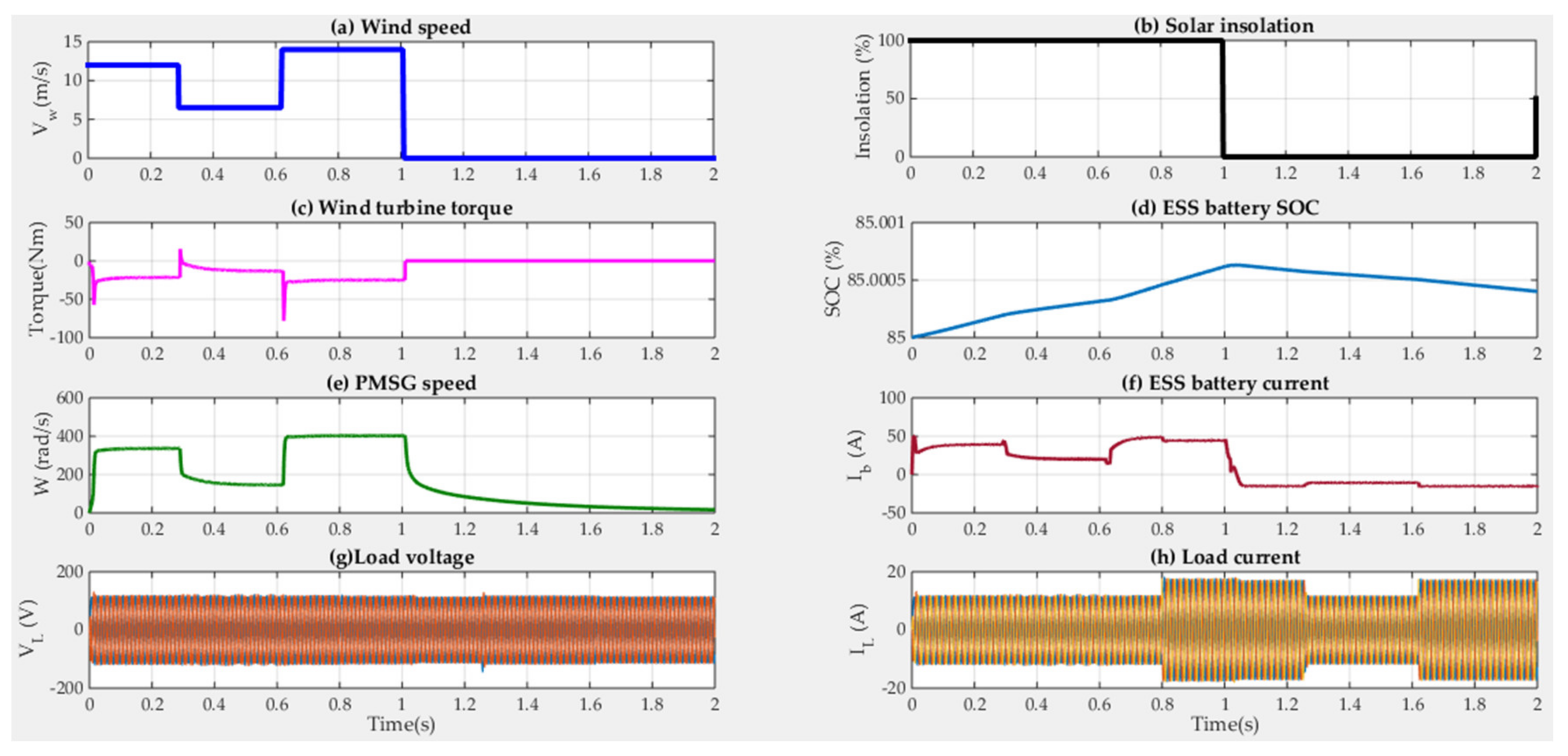
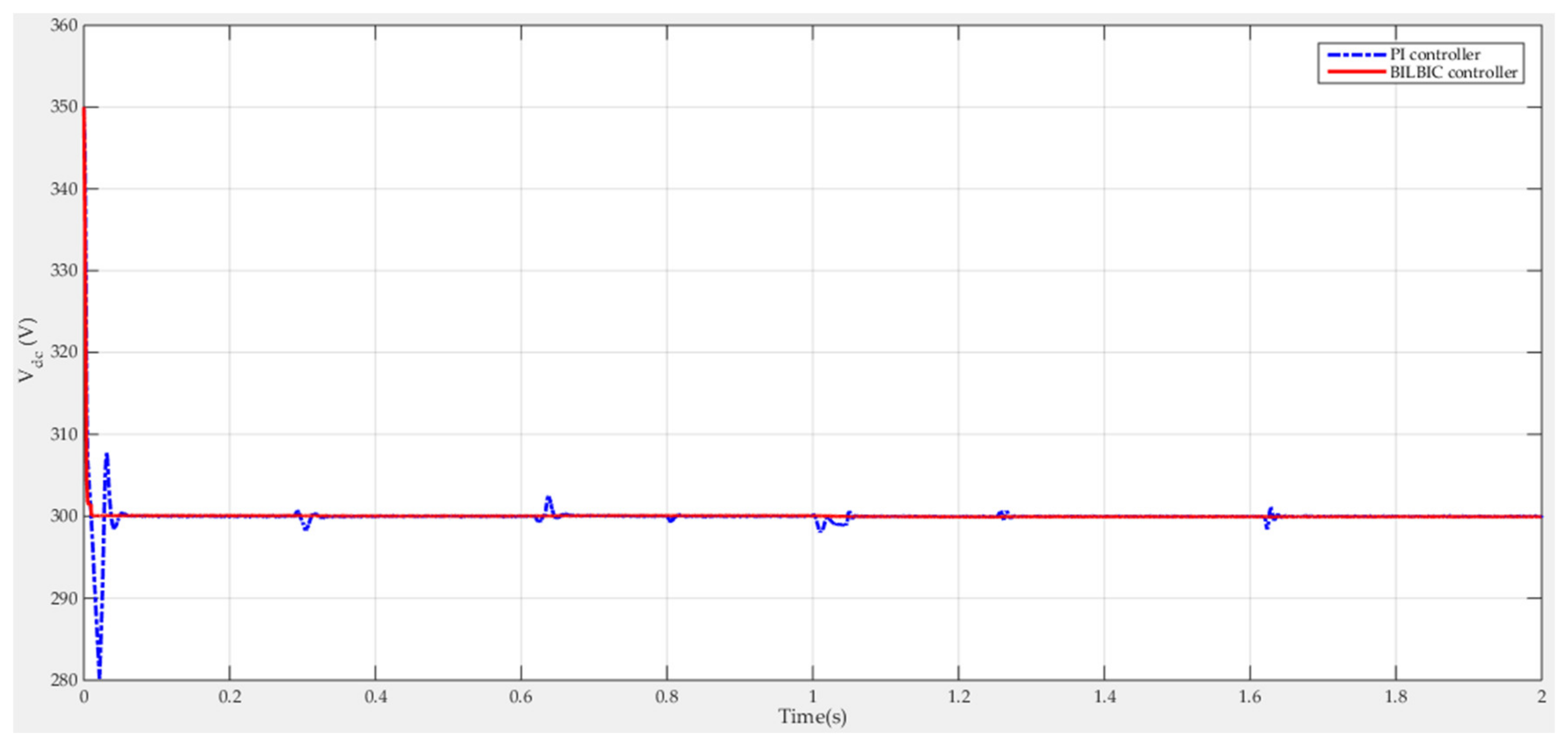
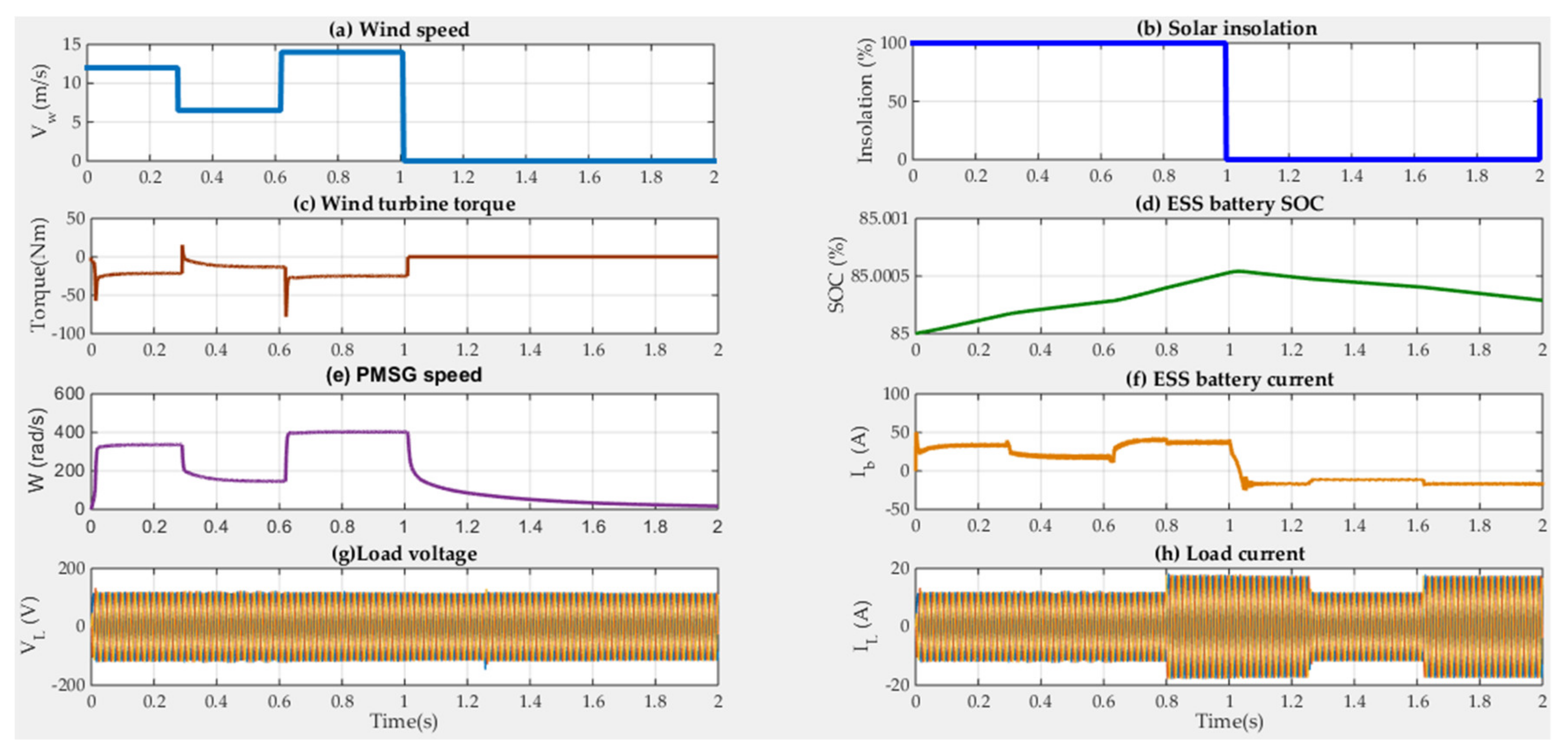
  • Simulating and implementing the proposed system in the MATLAB platform. Then, the system performance is tested under step and ramp changes in the system load, wind speed, and solar radiation. Moreover, the system stability against model parameter uncertainties and variations in the microgrid parameters are discussed.
The paper structure is as follows: Section 2 explains the introduced system structure. Section 3 gives the analysis of the introduced wind/PV microgrid. Section 4 presents the power system design. The design of the controllers and BELBIC are presented in Section 5. Section 6 discusses the simulation results. The conclusions are presented in Section 7.

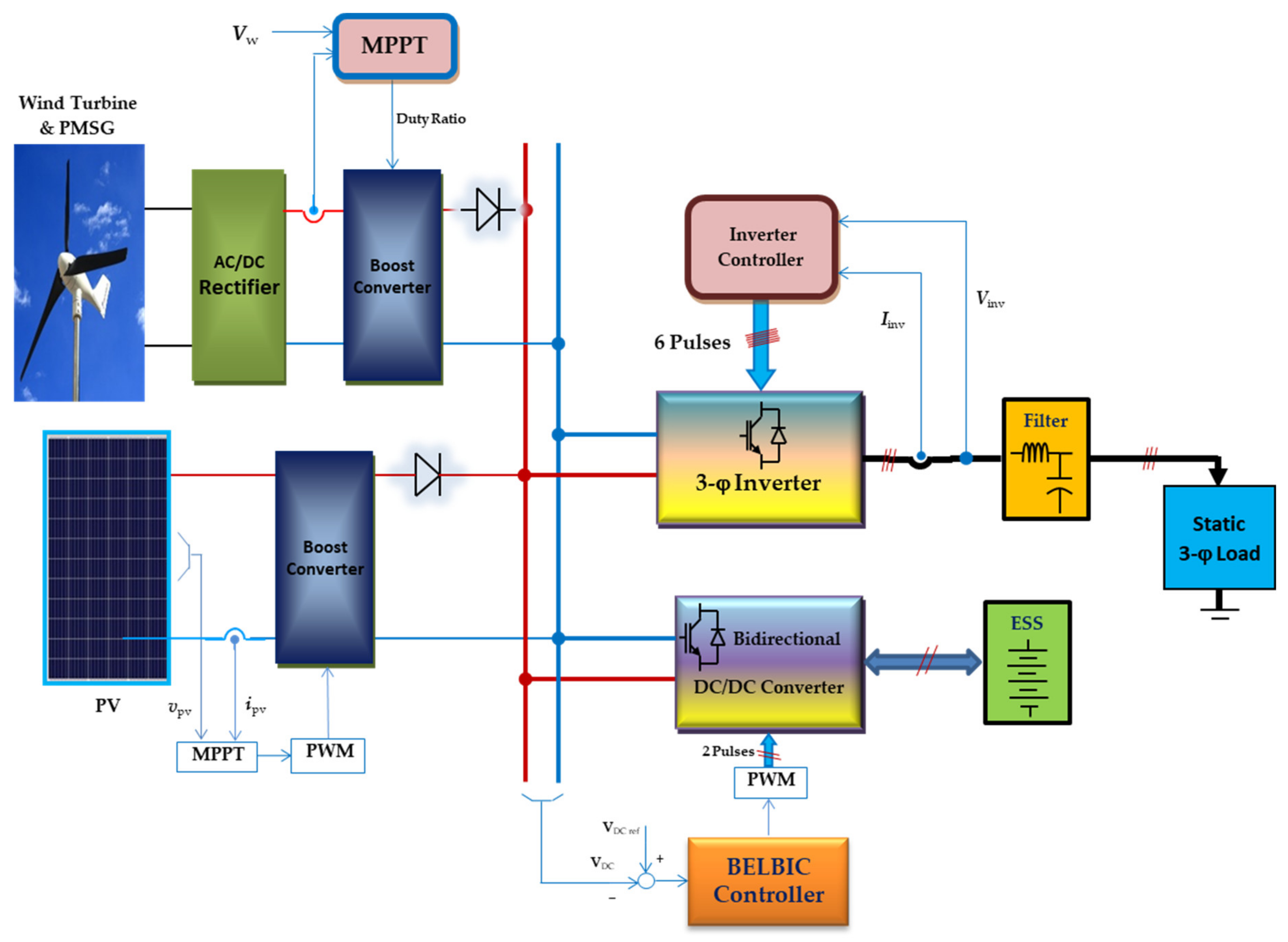
2. Explanation of the Proposed Microgrid

The proposed wind/PV standalone microgrid is presented in Figure 1. It has two renewable energy sources: wind and solar PV. Solar energy is available during the daytime. The availability of wind energy is not restricted to a certain time of the day. However, in some circumstances, the wind energy at night is greater than during day. Therefore, there is some form of integration between the two energy resources. Nevertheless, they do not generate steady energy due to the variations in the environmental state and solar irradiation. These issues give the wind and solar energies their intermittence nature. Hence, the utilization of the two resources increases the reliability and sustainability of the microgrid. Moreover, the size of the ESS system will be reduced.
The wind system includes the wind turbine coupled mechanically to a 3-φ Permanent Magnet Synchronous Generator (PMSG). The PMSG output is rectified through an uncontrolled rectifier, generating an unregulated DC voltage. This voltage is supplied to a boost converter. The function of the boost converter is to force the wind turbine towards the MPPT conditions. The output of the boost converter is attached to the DC bus of the microgrid.
The solar energy system consists of a PV array formed of three parallel stings. Each string includes modules. The PV output is supplied to another boost converter. Also, the boost converter is used to implement the MPPT conditions of the PV.
Due to the intermittent nature of the generated energy, ESS is usually utilized to compensate for the energy intermittency problem. The ESS consists of a group of lead-acid batteries connected in series and parallel to construct the required energy. These batteries are connected to the DC bus via a bidirectional converter. Generally, that converter is a DC/DC converter. Its function is to regulate the charge/discharge process of the ESS. Also, that converter represents the main adjustment actuator for the DC bus voltage and the microgrid energy balance.

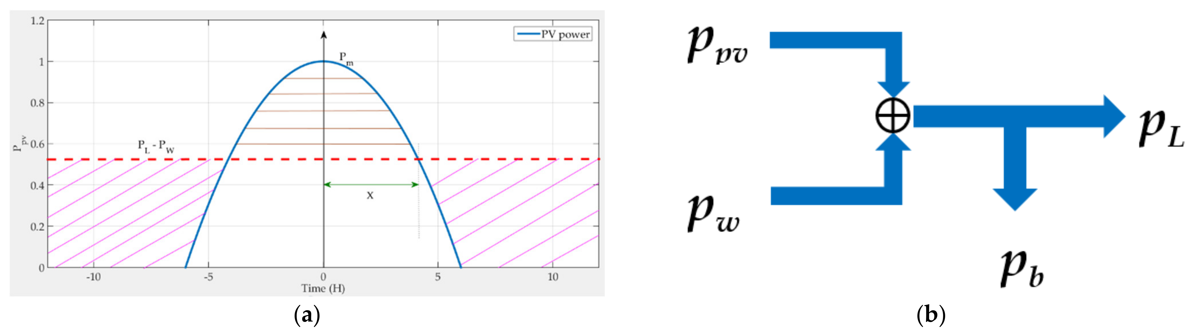
3. Power Analysis of the Proposed Wind/PV Microgrid

The design of the system relies mainly on the power and energy relations of the system. Hence, deriving these relations will aid the design procedure. In this regard, it is assumed that the initial state of energy of the ESS (Ei), the load power of the microgrid (PL), the swept area of the blades (A), the air density (ρ), and the average wind speed ( v ¯ ) are given. The first step is the derivation of the average wind and solar power.

3.1. Average Wind Power

To get the annual average wind power (Pw) over a certain site:
P w = 0 p v . f v d v
where (p(v)) is the wind power at the wind speed (v), and (f(v)) is the probability density function. Rayleigh is a common probability density function utilized for implementing the actual wind speed statistics; it is defined as [33]:
f v = π v 2 v ¯ e [ 0.25 π v / v ¯ 2 ]
The wind power as a function of the wind speed is given by:
p v = 0.5 ρ A v 3
Substituting (2) and (3) in (1), and completing the integration, the formula becomes:
P w = 3 π ρ A v ¯ 3
The average wind speed can be determined by gathering site data for a long time. If the value of ( v ¯ ) is determined, the average wind power is also determined.

3.2. Average Solar Power

Assume that the instantaneous PV power (ppv(t)) of the array, as shown in Figure 2a, is given by:
p p v t = P m 1 t 2 / 36
where (Pm) is the maximum PV power and (t) is the time in hours. The solar energy is provided to start at 6:00 AM and has a duration of 12 h.
The average PV power may be calculated as:
P p v = 1 24 6 6 P m 1 t 2 / 36 d t = 1 3 P m
The daily peak power (Pm) is determined from the statistics of the solar insolation at the specified site of the microgrid and averaged over the year.
The microgrid power flow diagram, presented in Figure 2b, generates the following instantaneous equation:
p p v t + p w t = p L t + p b t
where (pb(t)) is the instantaneous ESS power. Take the daily average of Equation (7), which leads to:
P p v + P w = P L + E i / 24
As the average power of the ESS is supposed to be constant at (Ei/24).

3.3. Energy Analysis of the ESS

In this section, the instantaneous stored energy (Eb) can be determined by:
d E b = p b t d t
From (7), the instantaneous stored power is:
p b t = P m 1 t 2 / 36 + p w t p L t 6 t 6 p w t p L t   6 t 18
Assuming that the wind and the load power are constants at their average values:
p w t p L t P w P L
Substituting (6), (8), and (10) into (9) and manipulating the integration:
E b t = 1 3 P m 6 + 2 t t 3 36 + E i 1.25 + t 24 6 t 6 E i 8 P m t 1 24 + 6 P m + 0.25 E i   6 t 18
Using traditional calculus, the maximum value of the stored energy takes place at:
t m a x = 24 + 1.5 E i P m
Hence, the maximum stored energy is given by:
E b m a x = E b t m a x
The rated energy storage can be determined using (14). From this analysis, if the required load power PL is given, then Equations (6), (8), and (14) can help to determine the power rating of the system components. Based on the previous analysis, the PV power and the ESS size can be determined. Assume that the load power demand and the wind turbine power are given. Assume a suitable value for (Ei). Usually, the SOC of the ESS is from 20% to 95% [34]. Hence, from (6), (8), and (14), the PV power and the ESS energy will be determined.

4. The Control System Design

The proposed system controllers, shown in Figure 3, are the wind-PV MPPT, the ESS and DC link voltage controller, and the load inverter controller. The functions of the MPPT controllers are to extract the peak power from the wind turbine and PV array. They generate the required duty cycle signal to the boost converter, which in turn loads the wind turbine and the PV array with the MPPT load conditions. However, the ESS and DC link voltage controller regulate the DC link voltage and the charge/discharge process of the ESS. The third controller is used to regulate the load inverter voltage and frequency. The control design of them will be discussed in the following subsections.

4.1. The Wind and PV Array MPPT Controllers

These controllers are important for better utilization of wind and PV energy. In the last few years, many MPPT approaches for wind/PV hybrid systems have been introduced [35]. A common and frequently utilized approach is called “Perturb and Observe” (P&O). It has the merits of simple implementation and a straightforward algorithm. Two boost converters are used for this issue, one for the wind and another for the PV array. The output of each MPPT controller is the value of the duty cycle switch of the boost converter. The P&O algorithms for the two energy sources are identical. A flowchart for the P&O algorithm is presented in [34].

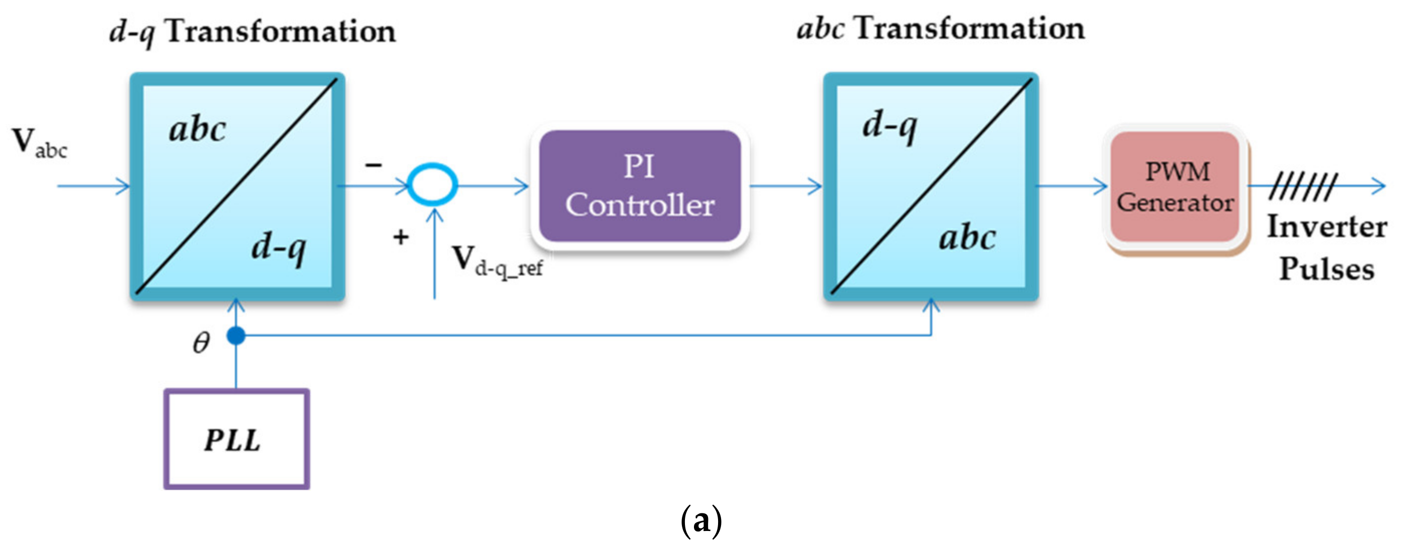
4.2. Load Inverter Controller

The objective of this controller is to supply the load with AC power at a regulated voltage and frequency. The control loop is shown in Figure 3a. The load 3-φ voltages are measured and transferred to the d-q frame with the help of Phase Locked Loop (PLL). The transferred d-q voltages are compared to their reference values. Then the resulting error is fed to a simple PI controller. Hence, the PI controller gains are tuned using the Ziegler–Nichols algorithm.

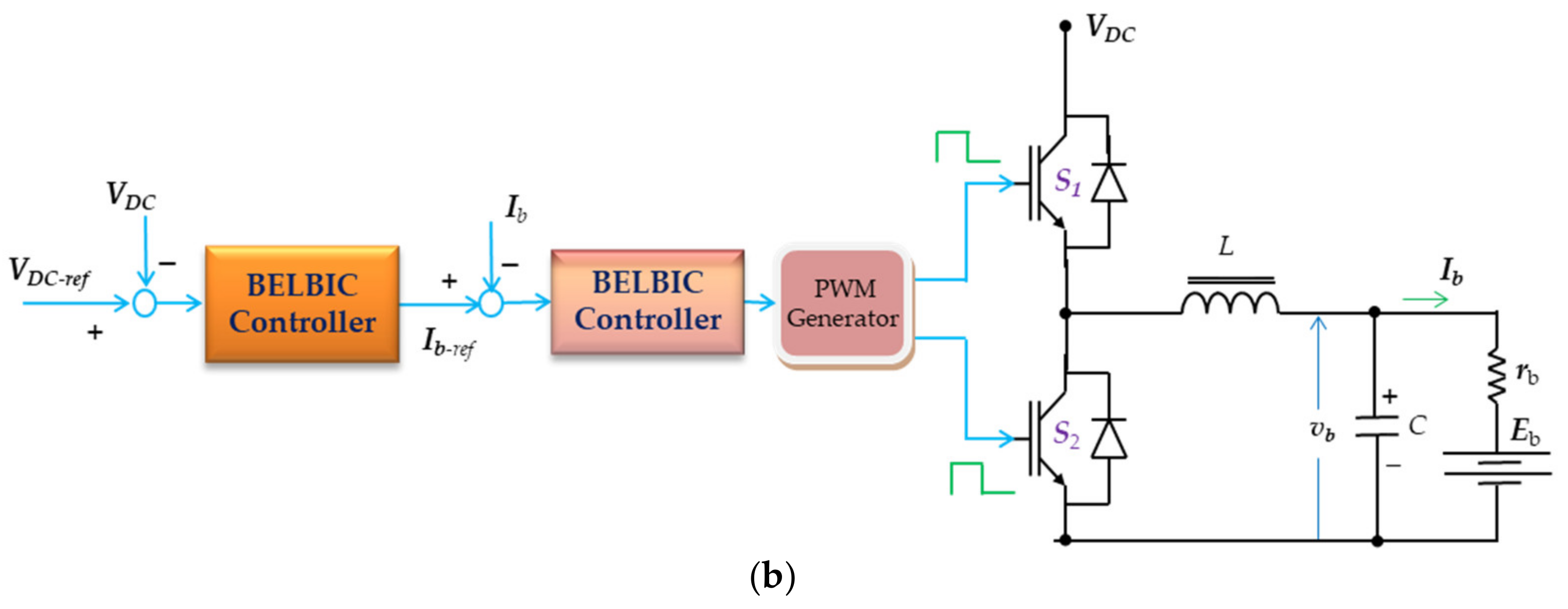
4.3. Storage and DC-Link Voltage Controller

Mainly, this controller aims to regulate the DC-link voltage that can be achieved by controlling the charging of the ESS. It includes two nested loops, as shown in Figure 3b. The outer loop adapts the DC-link voltage with the help of the BELBIC controller. However, the inner loop controls the ESS charging current with the help of another BELBIC controller. The output of the outer loop is the reference charging current of the inner loop. When the ESS is fully charged, the controller ends the charging process and the MPPT controllers stop.

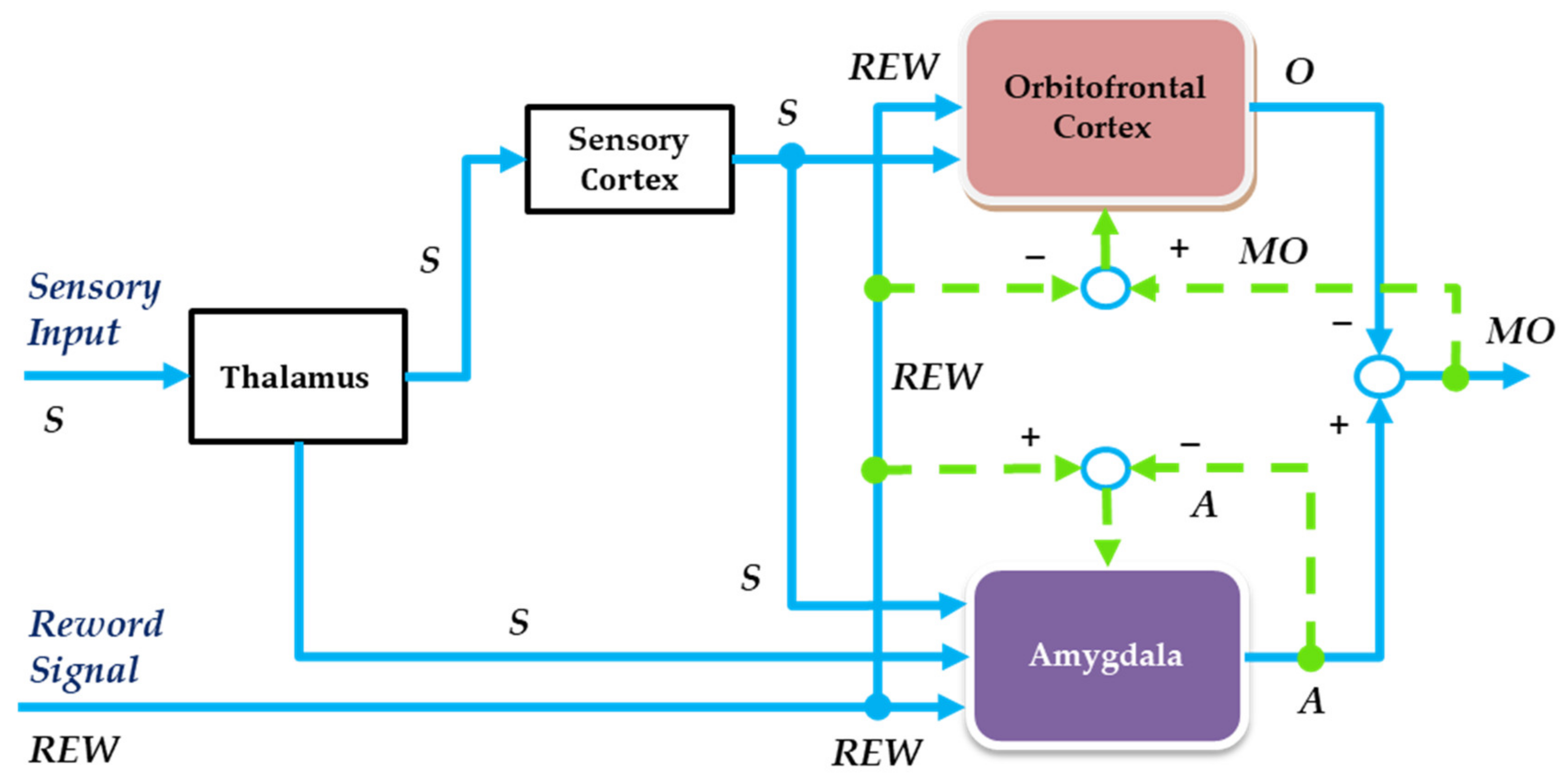
5. The BELBIC Controller Design

The BELBIC controller emulates the process applied by the brain to process emotions. Its computational network includes the orbitofrontal cortex, amygdala, thalamus, and sensory input cortex [29]. The schematic diagram of the BELBIC controller is shown in Figure 4. The sensory input signals are handled and partially processed by the thalamus section. The output of the thalamus is the input of the sensory cortex. It helps in subclassing and favoritism of the thalamus output. The function of the orbitofrontal cortex is to prevent unstable performances from the amygdala. The amygdala section helps in following up the stimulus motion. Subtracting the amygdala and orbitofrontal cortex output signals produces the BELBIC controller output. Each sensory cortex output (S) has one node (A) in the amygdala. Another node is set to the thalamus output. Except for the thalamic node, each stimulus has one node (O). The outputs of the amygdala and orbitofrontal cortex are subtracted to form a common output node (MO).
Hence, the net output node MO is given by:
M O = k A k k O k
The orbitofrontal part does not ban the thalamic signal. On the other hand, the other amygdala inputs are banned. Emotional learning, within the amygdala and the orbitofrontal cortex, is defined as:
Δ G A k i Δ G O k = α S k i max ( 0 ,   R E W k i A k i ) β S k R o
where
R o = max 0 ,   k A k R E W k O k   R E W 0 max 0 ,   k A k k O k   R E W = 0
The two learning rules of (16) are similar. The node values are represented by:
A k O k = G A k S k G O k S k
The BELBIC controller operates in two ways. The first way is to learn the amygdaloid, then let it predict and respond to a certain REW. The second way is to direct the orbitofrontal to track diversions between REW and the system’s predictions. Then it learned to ban the output corresponding to the diversions.
The REW signal is implemented based on the cost function used:
R E W = J e , y p , S k
Also, the sensory inputs are functions of the system outputs:
S k = f y p , u ,   r , e
where (u) is the controller output, (r) is the reference input, (yp) is the plant output, and (e) is an error signal.
The amygdala and the orbitofrontal have the continuous updating weights given by:
d G A k d t d G O k d t = α S k R E W A k β S k A k R E W O k

6. The Simulation Results

The introduced hybrid wind/PV microgrid is simulated by the MATLAB/Simulink platform. The introduced parameters of the microgrid are presented in Table 1.
The proposed wind/PV microgrid is simulated using the MATLAB/Simulink platform. The simulation results of the proposed microgrid with the BILBIC controller, according to step changes in the solar insolation, the wind speed, and load power, are shown in Figure 5. Figure 5a shows the solar insolation level variations. It has 100% insolation during the first second and drops to zero during the remaining time. The wind speed of the wind turbine is presented in Figure 5b. It has step changes at the times 0.3 s, 0.6 s, and 1 s, respectively. The wind turbine response is shown in Figure 5c, where the torque is directly proportional to the wind speed. Figure 5d shows the state of charge of the ESS. The ESS is continuously charging during the first second, then discharges. As the PV and wind power are available and sufficient until 1 s, the SOC increases. However, after (1 s) the energy is not sufficient to supply the load. Hence, the ESS discharges to compensate for the energy drop. The PMSG speed is presented in Figure 5e. It is proportional to the wind or the turbine speed, except for some transients related to the turbine inertia. Figure 5f shows the ESS charging and discharging currents. For the period from 0 to 0.3 s, the charging current is 35 A, which is relatively high, as the PV energy is full and the wind energy corresponds to a 12 m/s wind speed. For the period (0.3 to 0.6 s), the charging current is 25 A, moderate as the PV energy is full and the wind energy drops. For the period (0.6 s to 0.8 s), the charging current is 50 A high as the PV energy is full and the wind energy is full, corresponding to a 14 m/s wind speed. For the period (0.8 to 1 s), the charging current drops as the load is increased. For the period from 0.8 to 1 s, both wind and PV energy are inhibited. Hence, the ESS will compensate for them during this period. The load voltage and current are shown in Figure 5g,h. They are sinusoidal with a stable frequency, and the voltage has a constant amplitude despite all the disturbances.
Figure 6 compares the DC bus voltage responses for the BELBIC and PI controllers for the same microgrid. It tracks well with the reference voltage (300 V) for both controllers. However, the response of the BELBIC is excellent. It has no overshoot and smaller settling times.
To ensure robust stability against model parameter uncertainties, variations in the microgrid parameters are altered. Where the temperature of the PV is increased by 10%, the PV series resistance is increased by 10%, and the boost inductor of the wind MPPT is decreased by 10%. Figure 7 shows the proposed microgrid response with the BILBIC controller according to the previous step variations and under parameters uncertainties. It is indicated in the figure that the proposed controller can stabilize the load voltage and frequency with high accuracy, despite the modeling errors.
Figure 8 shows the spectrum analysis of the load current with the BELBIC and PI controllers. The load current THD in the case of the BELBIC controller is 2.22%. However, it is 3.68% in the case of the PI controller. The load current THD of both cases is lower than the standards specified in [36]. Hence, the load current quality is better in the case of the BELBIC controller than the PI controller.
The simulation results of the proposed microgrid with the BILBIC controller according to ramp variations in the solar insolation and the wind speed are shown in Figure 9. Also, step load changes at 0.8 s, 1.25 s, and 1.63 s are presented. The wind speed of the wind turbine has the ramp changes indicated in Figure 9a. Figure 9b shows the solar insolation level ramp variations. It has a ramp increase of the insolation during the first 0.3 s, however, the wind speed has a constant value (12 m/s) during this time. The ESS charging current is increasing during this period, shown in Figure 9c, as the wind energy increases. During the period (0.3 s < t < 0.8 s), the PV energy decays, and the wind energy increases. As the energy rate of change is different, there is a drop in the generated power and the charging current. During the period 0.8 s < t < 1.25 s, the PV energy is at 100% insolation, the wind energy is very low, and load power is increased by 50%. The charging current drops during this period. During the remaining period, the solar energy decreases and the wind energy increases. However, the net generation is not sufficient to supply the load. Hence, the ESS discharges to compensate for the energy drop and the charging current is negative.
Figure 9d shows the state of charge of the ESS. The ESS is tracking the charging current. It is the integration of the charging current. Hence, when the charging current is positive, the SOC increases and vice versa. Also, the load voltage and current, shown in Figure 9e,f, have sinusoidal waveforms with stable frequency during all the disturbances.
Table 2 shows a comparative analysis of the extracted results with that of ref. [30]. It can be noticed that the proposed system has the best performance over the others. The disturbance function used in [30] was a simple one-step change in the wind speed. However, complex multi-step disturbances in the wind speed and solar insolation are applied to the proposed system. Also, the parameter uncertainties were not studied in [30].

7. Conclusions

A hybrid wind/PV microgrid operating in standalone mode is proposed. The energy management and control of the microgrid are based on the recent BELBIC control technique. The microgrid includes a wind turbine, a PV array, two boost converters, an ESS system, a bidirectional DC/DC converter, and a DC/AC load inverter. The MPPT conditions for both the PV and the wind turbine are achieved using the P&O algorithm. A new simple analysis and design of the microgrid energy system are introduced. Also, closed-form equations for the system energies and ESS size are derived. The proposed wind/PV microgrid is simulated using MATLAB. The simulation results indicate that the system responses with the BELBIC controller are better than those of the conventional PI controller. The system is tested with varying wind speeds, solar insolation levels, and load power. At all disturbances, the load voltage is sinusoidal at constant amplitude and frequency with a perfect response. The load current THD in the case of the BELBIC controller has a maximum value of 2.22%. However, it is 3.68% in the case of the PI controller. The load current THD of both cases is lower than the standards. The DC link voltage response with the proposed controller has better performance than that of the PI controller. In addition, the energy management of the microgrid and the charging/discharging processes of the ESS proved to have perfect performance for energy compensation for all disturbances. On the other hand, the wind and PV MPPT points are precisely tracked by their controllers. To ensure robust stability against model parameters uncertainties, the temperature of the PV is increased by 10%, the PV series resistance is increased by 10%, and the boost inductor of the wind MPPT is decreased by 10%. The proposed microgrid response with the BILBIC controller can stabilize the load voltage and frequency with high accuracy despite the modeling errors.

Author Contributions

H.A. (Hani Albalawi) and H.A. (Hosam AbdelMeguid) collected the funding and resources; M.E.E.-S. and A.M.K. helped with controller tunning; and S.A.Z. conceived, designed the system model, and analyzed the results. All authors have read and agreed to the published version of the manuscript.

Funding

This research was funded by the University of Tabuk, Grant Number S-1441-0172 at https://www.ut.edu.sa/web/deanship-of-scientific-research/home (accessed on 13 April 2021).

Institutional Review Board Statement

Not applicable.

Informed Consent Statement

Not applicable.

Data Availability Statement

Not applicable.

Conflicts of Interest

The authors declare no conflict of interest.

References

  1. Yimen, N.; Tchotang, T.; Kanmogne, A.; Idriss, I.A.; Musa, B.; Aliyu, A.; Okonkwo, E.C.; Abba, S.I.; Tata, D.; Meva’a, L.; et al. Optimal sizing and techno-economic analysis of hybrid renewable energy systems—A case study of a photovoltaic/wind/battery/diesel system in Fanisau, Northern Nigeria. Processes 2020, 8, 1381. [Google Scholar] [CrossRef]
  2. Miller, I.; Gençer, E.; O’Sullivan, F.M. A general model for estimating emissions from integrated power generation and energy storage. case study: Integration of solar photovoltaic power and wind power with batteries. Processes 2018, 6, 267. [Google Scholar] [CrossRef] [Green Version]
  3. Nabipour-Afrouzi, H.; Wen Yii, S.H.; Ahmad, J.; Tabassum, M. Comprehensive Review on Appropriate Sizing and Optimization Technique of Hybrid PV-Wind System. In Proceedings of the 2018 IEEE PES Asia-Pacific Power and Energy Engineering Conference (APPEEC), Kota Kinabalu, Malaysia, 7–10 April 2018; pp. 364–369. [Google Scholar] [CrossRef]
  4. Merabet, A.; Tawfique Ahmed, K.; Ibrahim, H.; Beguenane, R.; Ghias, A.M.Y.M. Energy management and control system for laboratory scale microgrid based wind-PV-battery. IEEE Trans. Sustain. Energy 2017, 8, 145–154. [Google Scholar] [CrossRef]
  5. Angadi, S.; Yaragatti, U.R.; Suresh, Y.; Raju, A.B. Comprehensive review on solar, wind and hybrid wind-PV water pumping systems-an electrical engineering perspective. CPSS Trans. Power Electron. Appl. 2021, 6, 1–19. [Google Scholar] [CrossRef]
  6. Chaib, A.; Achour, D.; Kesraoui, M. Control of a solar PV/wind hybrid energy system. Energy Procedia 2016, 95, 89–97. [Google Scholar] [CrossRef] [Green Version]
  7. Prakash, S.L.; Arutchelvi, M.; Jesudaiyan, A.S. Autonomous PV-array excited wind-driven induction generator for off-grid application in India. IEEE J. Emerg. Sel. Top. Power Electron. 2016, 4, 1259–1269. [Google Scholar] [CrossRef]
  8. Traoré, A.K.; Cardenas, A.; Doumbia, M.L.; Agbossou, K. Comparative Study of Three Power Management Strategies of a Wind PV Hybrid Stand-Alone System for Agricultural Applications. In Proceedings of the IECON2018-44th Annual Conference of the IEEE Industrial Electronics Society, Washington, DC, USA, 21–23 October 2018; pp. 1711–1716. [Google Scholar]
  9. Pradhan, S.; Singh, B.; Panigrahi, B.K.; Murshid, S. A composite sliding mode controller for wind power extraction in remotely located solar PV–wind hybrid system. IEEE Trans. Ind. Electron. 2019, 66, 5321–5331. [Google Scholar] [CrossRef]
  10. Parida, A.; Chatterjee, D. Stand-alone AC-DC microgrid-based wind solar hybrid generation scheme with autonomous energy exchange topologies suitable for remote rural area power supply. Int. Trans. Electr. Energy Syst. 2018, 28, 2520. [Google Scholar] [CrossRef]
  11. Parida, A.; Choudhury, S.; Chatterjee, D. Microgrid based hybrid energy co-operative for grid-isolated remote rural village power supply for east coast zone of India. IEEE Trans. Sustain. Energy 2018, 9, 1375–1383. [Google Scholar] [CrossRef]
  12. Rezkallah, M.; Hamadi, A.; Chandra, A.; Singh, B. Design and implementation of active power control with improved P&O method for wind-PV-battery-based standalone generation system. IEEE Trans. Ind. Electron. 2018, 65, 5590–5600. [Google Scholar]
  13. Aloo, L.A.; Kihato, P.K.; Kamau, S.I.; Orenge, R.S. Model Predictive Control-Adaptive Neuro-Fuzzy Inference System Control Strategies for Photovoltaic-Wind Microgrid: Feasibility Review. In Proceedings of the 2020 IEEE PES/IAS PowerAfrica, Nairobi, Kenya, 25–28 August 2020; pp. 1–5. [Google Scholar] [CrossRef]
  14. Sujil, A.; Kumar, R.; Bansal, R.C. FCM Clustering-ANFIS-based PV and wind generation forecasting agent for energy management in a smart microgrid. IET J. Eng. 2019, 18, 4852–4857. [Google Scholar] [CrossRef]
  15. Arfeen, Z.A.; Khairuddin, A.B.; Larik, R.M.; Saeed, M.S. Control of distributed generation systems for microgrid applications: A technological review. Int. Trans. Elec. Energy Syst. 2019, 29, e12072. [Google Scholar] [CrossRef] [Green Version]
  16. Ahmadi, S.M.; Fateh, M.M. Task-space asymptotic tracking control of robots using a direct adaptive Taylor series controller. J. Vib. Control 2018, 24, 5570–5584. [Google Scholar] [CrossRef]
  17. Wei, Y.; Qiu, J.; Karimi, H.R. Reliable Output Feedback Control of Discrete-Time Fuzzy Affine Systems with Actuator Faults. IEEE Trans. Circuits Syst. I Reg. Pap. 2017, 64, 170–181. [Google Scholar] [CrossRef]
  18. Zirkohi, M.M. Direct adaptive function approximation techniques-based control of robot manipulators. J. Dyn. Syst. Meas. Contr. 2018, 140, 011006. [Google Scholar] [CrossRef]
  19. Kayacan, E.; Kayacan, E.; Ramon, H.; Saeys, W. Adaptive neuro-fuzzy control of a spherical rolling robot using sliding-mode-control-theory-based online learning algorithm. IEEE Trans. Cybern. 2013, 43, 170–179. [Google Scholar] [CrossRef]
  20. Mushage, B.O.; Chedjou, J.C.; Kyamakya, K. An extended neuro-fuzzybased robust adaptive sliding mode controller for linearizable systems and its application on a new chaotic system. Nonlinear Dyn. 2016, 83, 1601–1619. [Google Scholar] [CrossRef]
  21. Miranian, A.; Abdollahzade, M. Developing a local least-squares support vector machines-based neuro-fuzzy model for nonlinear and chaotic time series prediction. IEEE Trans. Neural Netw. Learn. Syst. 2013, 24, 207–218. [Google Scholar] [CrossRef]
  22. Azadeh, A.; Gaeini, Z.; Haghighi, S.M.; Nasirian, B. A unique adaptive neuro fuzzy inference system for Optimum decision making process in a natural gas transmission unit. J. Nat. Gas. Sci. Eng. 2016, 34, 472–485. [Google Scholar] [CrossRef] [Green Version]
  23. Petković, D.; Shamshirband, S.; Anuar, N.B.; Sabri, A.Q.M.; Rahman, Z.B.A.; Pavlovic, N.D. Input displacement neuro-fuzzy control and object recognition by compliant multi-fingered passively adaptive robotic gripper. J. Intell. Robot. Syst. 2016, 82, 177–187. [Google Scholar] [CrossRef]
  24. Lotfi, E.; Rezaee, A.A. Generalized BELBIC; Neural Computing and Applications; Springer: Berlin, Germany, 2018. [Google Scholar]
  25. Sharma, P. Design of novel BELBIC controlled semi-active suspension and comparative analysis with passive and PID controlled suspension. Walailak J. Sci. Technol. 2021, 18, 8989. [Google Scholar] [CrossRef]
  26. Ershadi, M.H.; Shojaeian, S.; Keramat, R. A comparison of fuzzy and brain emotional learning-based intelligent control approaches for a full bridge DC-DC converter. Int. J. Ind. Electron. Control Optim. 2019, 2, 197–206. [Google Scholar]
  27. Zirkohi, M.M. Stability analysis of brain emotional intelligent controller with application to electrically driven robot manipulators. IET Sci. Meas. Technol. 2020, 14, 182–187. [Google Scholar] [CrossRef]
  28. Sharma, P.; Kumar, V. Design and analysis of novel bio inspired BELBIC and PSOBELBIC controlled semi active suspension. Int. J. Veh. Perform. 2020, 6, 399–424. [Google Scholar] [CrossRef]
  29. Abd El-Gawad, A.; Elden, A.N.; Bahgat, M.E.; Ghany, A.A. BELBIC Load Frequency Controller Design for a Hydro-Thermal Power System. In Proceedings of the 2019 21st International Middle East Power Systems Conference (MEPCON), Cairo, Egypt, 17–19 December 2019. [Google Scholar]
  30. Al Alahmadi, A.A.; Belkhier, Y.; Ullah, N.; Abeida, H.; Soliman, M.S.; Khraisat, Y.S.H.; Alharbi, Y.M. Hybrid wind/PV/battery energy management-based intelligent non-integer control for smart DC-microgrid of smart university. IEEE Access 2021, 9, 98948–98961. [Google Scholar] [CrossRef]
  31. Karan, D.; Harish, V.S.K.V. Analysis of a wind-PV battery hybrid renewable energy system for a dc microgrid. Mater. Today Proc. 2021, 46, 5451–5457. [Google Scholar]
  32. Kumar, G.B. Optimal power point tracking of solar and wind energy in a hybrid wind solar energy system. Int. J. Energy Environ. Eng. 2021, 1–27. [Google Scholar] [CrossRef]
  33. Masters, G.M. Renewable and Efficient Electric Power Systems, 2nd ed.; Wiley-IEEE Press: New York, NY, USA, 2013. [Google Scholar]
  34. Atawi, I.E.; Hendawi, E.; Zaid, S.A. Analysis and design of a standalone electric vehicle charging station supplied by photovoltaic energy. Processes 2021, 9, 1246. [Google Scholar] [CrossRef]
  35. Saad, S.S.; Zainuri, M.A.A.M.; Hussain, A. Implementation of Maximum Power Point Tracking Techniques for PV-Wind Hybrid Energy System: A Review. In Proceedings of the 2021 International Conference on Electrical Engineering and Informatics (ICEEI), Kuala Terengganu, Malaysia, 12–13 October 2021; pp. 1–6. [Google Scholar] [CrossRef]
  36. IEEE-519; IEEE Recommended Practices and Requirements for Harmonic Control in Electric Power Systems. IEEE: New York, NY, USA, 1992.
Figure 1. The proposed standalone Wind/PV microgrid.
Sustainability 14 04775 g001
Figure 2. (a) The daily PV array power and (b) the system power flow diagram.
Sustainability 14 04775 g002
Figure 3. (a) The load inverter controller and (b) the storage and DC-link voltage controller.
Sustainability 14 04775 g003aSustainability 14 04775 g003b
Figure 4. Scheme of the BELBIC structure.
Sustainability 14 04775 g004
Figure 5. Simulation results of the proposed microgrid with the BILBIC controller (a) wind speed, (b) PV irradiation level, (c) wind turbine torque, (d) ESS battery SOC, (e) PMSG speed, (f) ESS battery current, (g) load voltage, and (h) load current.
Sustainability 14 04775 g005
Figure 6. The DC link voltage response of the classical PI and BELBIC controllers.
Sustainability 14 04775 g006
Figure 7. Simulation results of the proposed microgrid with the BILBIC controller under parameters uncertainty (a) wind speed, (b) PV irradiation level, (c) wind turbine torque, (d) ESS battery SOC, (e) PMSG speed, (f) ESS battery current, (g) load voltage, and (h) load current.
Sustainability 14 04775 g007
Figure 8. Spectrum analysis of the load current with the (a) BELBIC controller and (b) PI controller.
Sustainability 14 04775 g008
Figure 9. Simulation results of the proposed microgrid with BILBIC controller under ramp variations of the wind speed and solar insolation (a) wind speed, (b) PV irradiation level, (c) ESS battery current, (d) ESS battery SOC, (e) load voltage, and (f) load current.
Sustainability 14 04775 g009
Table 1. Proposed Microgrid Parameters.
ItemParameterValue
Wind turbineRated power10 KW
Rated wind speed12 m/s
wind speed range3.5–25 m/s
PVSC current21.2 A
OC voltage257.1 V
Max. power5.4 kW
LoadVoltage110 V
Frequency50 Hz
Table 2. Comparative analysis of the extracted results with that of ref. [30].
ControllerProposed BELBICFuzzy PID [30]PI
Disturbance complexityComplexsimpleComplex
Parameters uncertaintyOKNANA
DC link Voltage responseOvershoot0%7%9%
Error0%5%0%
Load current THD2.22%NA3.68%
Publisher’s Note: MDPI stays neutral with regard to jurisdictional claims in published maps and institutional affiliations.

