Review

Emerging Solvent Regeneration Technologies for CO2 Capture through Offshore Natural Gas Purification Processes

by
Mohd Mu’Izzuddin Mohd Pauzi
1,2,
Nurulhuda Azmi
1,2 and
Kok Keong Lau
1,2,*
1
CO2 Research Center (CO2RES), Institute of Contaminant Management, Universiti Teknologi PETRONAS, Bandar Seri Iskandar 32610, Malaysia
2
Chemical Engineering Department, Universiti Teknologi PETRONAS, Bandar Seri Iskandar 32610, Malaysia
*
Author to whom correspondence should be addressed.
Sustainability 2022, 14(7), 4350; https://doi.org/10.3390/su14074350
Submission received: 6 March 2022 / Revised: 24 March 2022 / Accepted: 25 March 2022 / Published: 6 April 2022
(This article belongs to the Special Issue Advances in Gas Separation Technologies for Green Process Engineering)

Abstract

:
It is estimated that 40% of natural gas reservoirs in the world are contaminated with acid gases (such as hydrogen sulfide and carbon dioxide), which hinder exploitation activities. The demand for natural gas will increase by 30% from 2020 to 2050, with the rise of industrial activities and the lifting of travel restrictions. The long-term production of these high acid-gas fields requires mitigation plans, which include carbon capture, utilization, and a storage process to reduce carbon emissions. Absorption is one the most established technologies for CO2 capture, yet it suffers from extensive energy regeneration and footprint requirements in offshore operations. Therefore, the aims of this paper are to review and analyze the recent developments in conventional and emerging solvent regeneration technologies, which include a conventional packed-bed column, membrane contactor, microwave heating, flash drum, rotating packed bed, and ultrasonic irradiation process. The conventional packed column and flash drum are less complex, with minimum maintenance requirements, but suffer from a large footprint. Even though the rotating packed-bed column and microwave heating demonstrate a higher solvent flexibility and process stability, both technologies require regular maintenance and high regeneration energy. Membrane contactor and ultrasonic irradiation absorption systems are compact, but restricted by various operational issues.

1. Introduction

The issues of global warming and climate change have become a subject of intense interest all over the world since the last decade. The warming of the climate system is now evidenced from observations of increasing global average air and ocean temperatures, the widespread melting of snow and ice, and the rising global average sea level. This scenario will undoubtedly give rise to the destruction of the ecosystem, biodiversity, and human economic activities, both in the short and long terms [1]. The anthropogenic (human-caused) driver of climate change is the increasing concentration of greenhouse gases (GHGs) in the atmosphere [2]. Carbon dioxide (CO2) is the largest contributor to GHGs with regard to the amount present in the atmosphere, where it contributes to 65% of global warming effects, primarily as a result of burning coal, oil, and natural gas [3]. Despite the presence of other GHGs, CO2 receives the most attention due to its long lifespan in the atmosphere, which makes it the most critical gas when tackling the issues of climate change. Archer et al. reported that the time needed for 70%, 20%, and 10% of emitted CO2 to remain in the atmosphere is 100 years, 1000 years, and 10,000 years, respectively [4]. The International Panel of Climate Change (IPCC) predicted that the atmospheric content of CO2 can reach up to 570 ppmv, leading to an increment in the mean sea level by 3.8 cm and a rise in the global mean temperature of about 2 °C by the year 2100 [5]. If the phenomenon remains unchanged, the devastating effects on the world’s population will be unavoidable. The total CO2 emissions gradually increased from 1990 to 2002, and drastically increased after 2019 due to rapid industrialization as reported by International Energy Agency (IEA) [6]. The CO2 emission trend showed a notable decline of 9.7%, shifting from 33.4 GtCO2 in 2019 to 31.5 GtCO2 at the end of 2020. The observed trend was due to the reduction in CO2 emissions in power generation, ground transportation, and the industrial sector, as lockdowns were implemented to curb the rapid spread of COVID-19. However, the CO2 emission savings as a result of the drastic lockdown were only temporary and showed no significant impact on the global atmospheric CO2 levels [7]. It is expected the CO2 emissions will increase again with the rise in industrial activities and the lifting of travel restrictions. Thus, it is remains crucial to study and mitigate about 50% of CO2 emissions by 2030 to prevent the increase in the global mean temperature of more than 1.5 °C [8]. In order to prevent major climate change, CO2 concentration in the atmosphere should be reduced either by the CO2 uptake from the atmosphere, biologically, or the high CO2 emissions from the sources of fuel-combustion activities, industrial processes, and natural-gas processing [9].
By virtue of the world’s dependency on oil and gas as the main sources of energy that is expected to rapidly increase, the usage of level of natural gas globally is approximately 128 billion cubic feet and keeps increasing year by year, as reported by the International Energy Statistic [10]. The energy industry motivates an exploration of the high CO2 content and impurities of the natural gas reservoirs due to the high demand worldwide. To date, more than 40% of natural gas reservoirs in the world are contaminated with acid gases (such as hydrogen sulfide and carbon dioxide), which hinder the exploitation activities [11]. This paper focuses on the global attention to reduce carbon emissions through offshore natural gas processes, mainly the CO2 that is present in the original reservoir gas composition.
One crucial strategy for meeting CO2 emission reduction targets around the world is carbon capture and sequestration (CCS) technology. CCS has been a commercially safe operation for over 45 years, through which almost more than 20 million ppm of CO2 have been captured and injected into the reservoir since 1972 [12]. There are three steps in CCS, which involves capturing CO2 at the source, compressing it for transportation via pipelines, and injecting it deep into a rock formation at a carefully selected and safe site, where it is permanently stored. The carbon capture involves the development of CO2 capture technology for offshore natural gas purification. Recently, a wide range of conventional technologies, such as absorption, adsorption, membrane and cryogenic separation have been further explored to enhance carbon capture technologies for offshore natural gas purification [13].
The adsorption method has started to gain more attention as a method to remove CO2 from the natural gas streams. This technology has been identified with having a low energy penalty and high energy efficiencies [14]. Solid adsorbents, such as zeolites and activated carbon, allow the gas to accumulate on their surface, forming a film of molecules or atoms due to molecular attraction to the solid surface in a wide range of operating conditions. The process depends upon the intermolecular forces between the adsorbent and the CO2. The adsorbent is set in the form of a bed in a column and CO2 is then assimilated. The concerns for this technology are the scale-up and need to develop CO2-specific adsorbent materials. The adsorbent has shown rapid deactivation, and a longer desorption time is required during the regeneration process. The development of CO2 adsorbents should satisfy low-cost raw materials, low heat capacity, fast kinetics, high CO2 adsorption capacity, high CO2 selectivity, and thermal, chemical, and mechanical stabilities under extensive cycling [15]. In addition, an emerging CO2 adsorption process using helium has been proposed to mitigate the energy penalty for CO2 capture by reducing the process temperature [16].
The membrane system includes thin barriers that allow for the selective permeation of one component in the gas stream to pass through faster than the others [17]. It is a pressure-driven process in which the pressure exerted on the solution at one side of the membrane serves as a driving force to separate it into a permeate and a retentate [18]. It offers several advantages over other technologies, including its relatively smaller size and simplicity, which has been identified as moderate technology readiness for commercialization [19]. Nevertheless, membrane separation is accompanied by several challenges in achieving high degrees of separation, so multiple stages and/or the recycling of one of the streams is necessary. This leads to an increase in the complexity, energy consumption, and costs [20]. The good membrane for post-combustion CO2 capture should have some characterizations, such as high CO2 permeability, high selectivity, high thermal and chemical stability, resistance to plasticization, resistance to aging, and cost effectiveness [21,22].
Cryogenic separation is a technology that is mostly used for CO2 removal from natural gas streams with high CO2 concentrations (typically > 50%) [13]. The cryogenic method involves the separation of the gas mixtures by fractional condensation and distillation at a lower temperature [23]. The process is better than other technologies in several ways, for example, it consumes less energy duty and does not require regeneration and chemical utilization [13]. However, CO2 removal from natural gas via the cryogenic process needs a highly dehydrated gas stream, which increases the operating and capital cost for the separation process. Additionally, the existence of other gases may obstruct the cooling process and contribute to corrosion problems. The cryogenic process also faces the risk of solid formation due to the complex phase behavior range of CO2 [24].
Hydrate-based CO2 separation is an alternative technology, in which the natural gas containing CO2 is exposed to water at low temperature and high-pressure conditions [25,26]. The basic mechanism of the process is a selective partition of the target components between the hydrate and gas phases. To be specific, CO2 can form hydrates easier than other gases, such as N2, due to the differences in the phase equilibrium. The potential barriers of this technology are the ability to release CO2 from the hydrate in an energy-efficient manner, the efficient capture of CO2, stable prehydrate, and trace contaminants interfering with the hydrate formation [27]. The need to accelerate the hydrate formation rate and increase the capacity of CO2 uptake has become a limitation for the use of hydrate-based CO2 capture technology [28].
To date, absorption technology is one of the most widely used forms of technology used to remove sour gas from natural gas or post-combustion streams. CO2 separation via absorption is widely used in the industry, due to its capability to be operated under a broad range of CO2 compositions and lower hydrocarbon losses. In this separation process, CO2 dissolves into the absorbent and a low temperature is required to ensure a high rapport of CO2 absorption. The distribution of CO2 occurs between the gas–liquid interface and the bulk gas, prior to the reaction with the solvent [29]. In the physical solvent process, an organic solvent, such as methanol, was used to allow CO2 to permeate and dissolve the gas in the liquid phase [15]. The chemical absorption process using aqueous alkanolamine solutions is proposed to be the most applicable technology for a relatively low CO2 partial pressure system, compared to a physical solvent, as illustrated in Figure 1 [30]. However, the physical solvent could perform well at high CO2 partial pressure, which leads to a better absorption capacity when compared to the chemical solvent. Hence, the physical absorption has an advantage in the system with a higher CO2 partial pressure. The aqueous alkanolamine solvent is widely used in gas purification plants, due to its characteristics that are good in relation to physicochemical parameters. Alkanolamine has a high reactivity towards CO2, a low production cost, and high CO2 loading [31]. In the amine gas processing operation, the gas stream and liquid amine solution are contacted by a countercurrent flow in an absorption tower. However, the process suffered several drawbacks, including a high corrosion rate, amine degradation, high energy consumption, and requires a larger size of equipment [32]. Thus, the researchers actively made an effort to develop innovative solvents to overcome the drawbacks of the conventional sorbents [33,34]. In the past decade, ionic liquids (ILs) have been proposed as promising alternatives, due to their inherent structure tunability, good affinity with CO2, and low volatility liquids [35,36]. Haghbakhsh and Raeissi investigated the feasibility of one of the IL classes, deep eutectic solvents (DESs), to be a new generation of green solvents for CO2 separation [37,38].
The selection of specific CO2 capture technologies has become crucial, which heavily depends on CO2 partial pressure, energy consumption, and footprint requirement [24,39]. Figure 2 illustrates the comparison of CO2 capture technologies with respect to the CO2 concentration in flue gas, energy consumption, and footprint [40,41,42]. For offshore natural gas purification, energy consumption and a compact footprint requirement are among the crucial factors to be considered. Even though the absorption has been proven to be the most established CO2 capture technology, the conventional solvent regeneration process generally requires excessive energy and footprint/tonnage, which make the overall operation not economically viable for offshore natural gas purification [5].
Thus, the conventional and emerging solvent regeneration technologies are critically discussed and analyzed in this review paper. In this work, the flash drum is compared to the developing regeneration technologies, such as membrane contactor, microwave heating, rotating packed bed, and ultrasonic irradiation, in terms of footprint and energy consumption. It is crucial to determine the most promising solvent regeneration technology, which has the capability to overcome the limitations of conventional stripper columns.

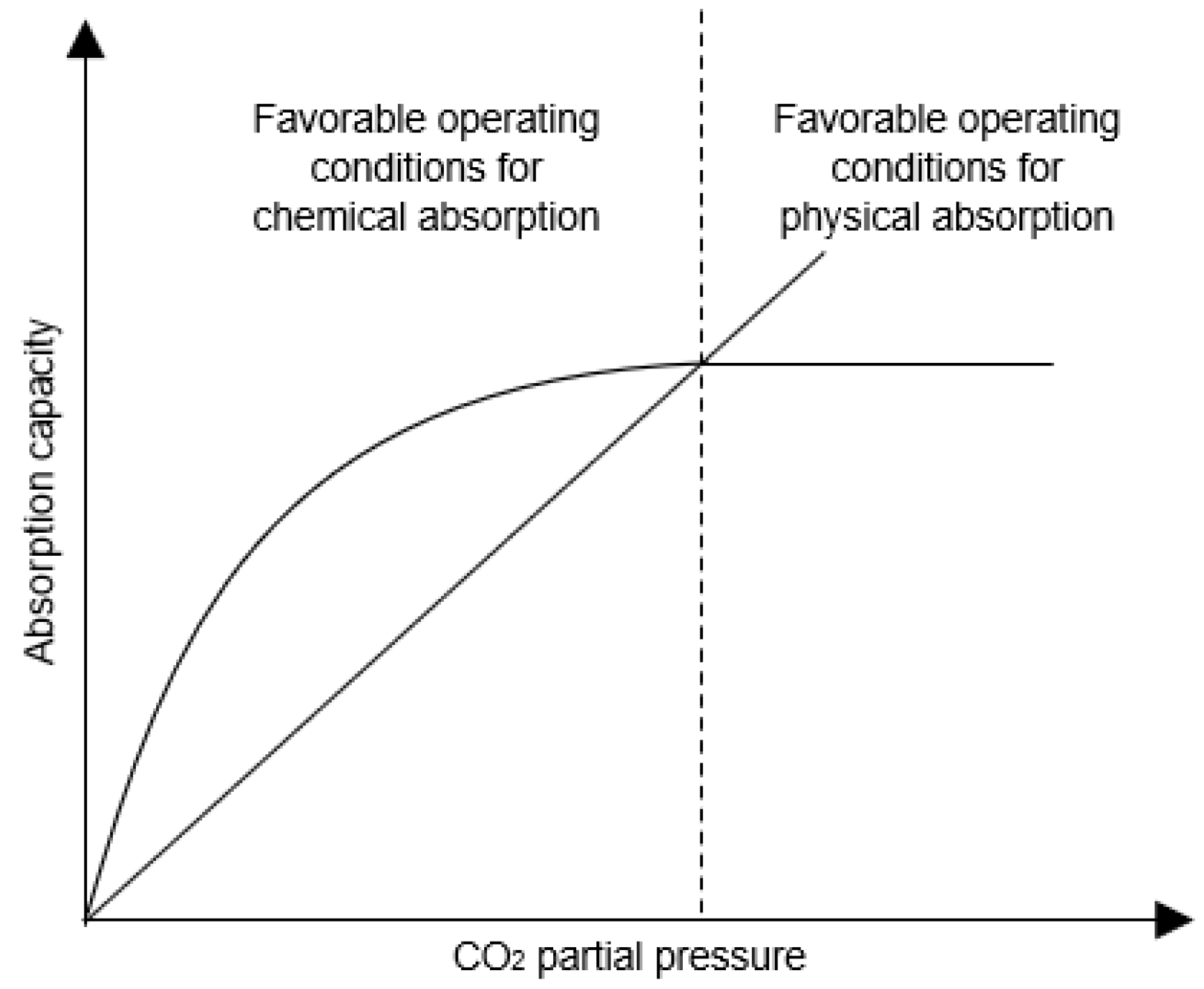
2. Conventional Absorption and the Regeneration Operation

In the petroleum and chemical industries, the technology based on liquid absorption is the most mature and commercially available amongst the above-mentioned CO2 capture options. Absorption by using a chemical solvent is developed from the reaction between CO2 with one or more basic absorbents that have a specialty to absorb the CO2 in a high capacity. Several solvents have been adopted for capturing CO2 from the gas streams, in which amines with alkaline properties are most extensively used to absorb acid gases [43,44]. The treatment of amine gas using a monoethanolamine (MEA) solution is the most advanced process in coal-fired power plants for CO2 removal, which produces more than 90% of absorption efficiency [45]. In terms of the unit operation, the absorption process is carried out in an absorber that acts as a gas–liquid contractor. The various absorber types, including the packed-bed, tray-tower, and bubble columns, can be used for the CO2 absorption process.
A stripper, normally designed as a packed-bed/tray column, is the primary device for the regeneration process, which involves the physical mass transfer process and reactions. The absorbed CO2 in the rich solvent is separated by altering the temperature and pressure in the stripper tower [46]. Figure 3 shows the basic absorber and stripper configuration. The feed gas passes through the absorber column from the bottom to the top, in which approximately 85–90 vol% of CO2 is absorbed by the solvent [47]. The CO2-rich solvent is further passed to the stripper to regenerate the solvent, prior to recycling, back to the absorber. The temperature inside the stripper needs to increase for the solvent regeneration process to occur. This thermal regeneration is the most basic and common technique used for CO2 removal. The regenerated solvent is then sent back to the absorber for the adsorption process, thus creating the continuous recycle process. However, the conventional packed-bed/tray regeneration column suffers from several operational issues, including high energy requirements for stripping, excessive footprint/tonnage, and solvent thermal degradation, during the offshore purification process [48].

3. Emerging Solvent Regeneration Technologies

During the past decades, various regeneration technologies have been proposed to minimize the generation energy and footprint requirement, compared to the conventional packed-bed/tray regeneration column. Therefore, it is crucial to review the development and improvement of each emerging solvent regeneration technology here, to further evaluate their advantages and limitations in this area of research.

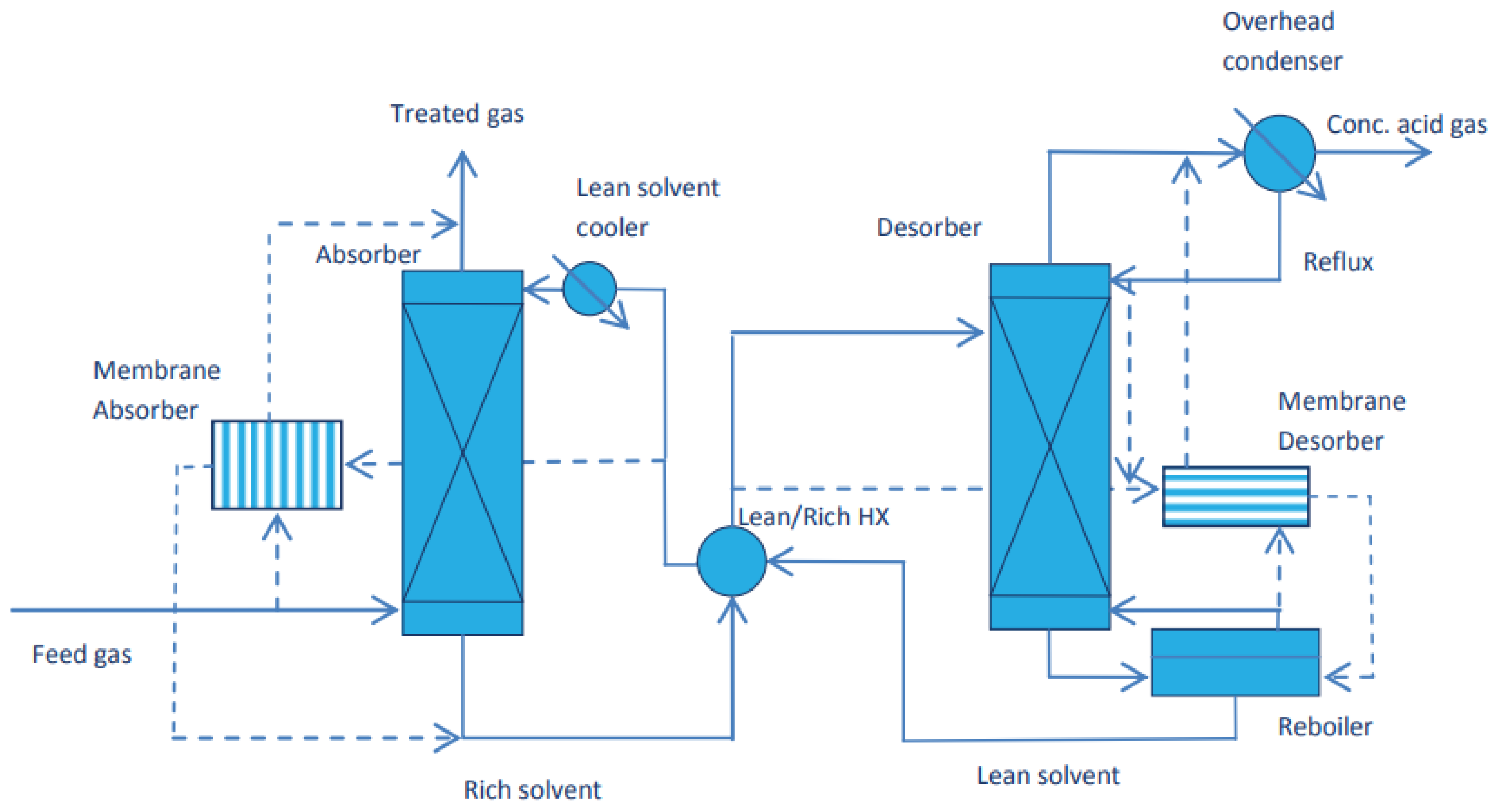
3.1. Membrane Contractor

A membrane contactor, having the advantages of a high surface area and high operational flexibility for ease of modularization, is a form of technology that has become a potential candidate for CO2 desorption [50]. The membrane contactor also possesses additional benefits as the gas and solvent have separate flow paths that can prevent foaming, flooding, entrainment, and channeling issues [51]. The membrane contactor technology has also been extensively studied by numerous researchers as it has the advantages of a large surface area for the mass transfer, it is lightweight, and has a small footprint for the system [52].
In the desorption process, the membrane is used as the non-selective barrier that is placed between two phases to keep these phases in contact and separated at the same time [53]. The selected gas is diffused to the permeate side through the membrane pores. Then, a sweep gas or steam sweeps out the CO2 gas on the permeate side to enhance the driving force for stripping the CO2. The steam is condensed to produce a high purity of CO2. Figure 4 illustrates the mechanism of the membrane contactor during solvent regeneration [54].
The materials used in the membrane play an important role in controlling the efficiency of mass transfer for both the absorption and desorption of CO2 gas. The porous membrane contactor has been comprehensively studied for its property as a solvent absorption, and the CO2 is in direct contact with the pores of the membranes to facilitate the mass transfer. Nobuhide Takahashi et al. performed a study on the effect of membrane pore sizes towards the performance of CO2 desorption. Three different pore sizes, 0.2, 0.5, and 1.0 µm, of a microfiltration membrane (MF) were used to investigate the rate of CO2 desorption in 30 wt% monoethanolamine (MEA) solvent regeneration at a temperature of 40 °C. They found that the smallest membrane size (0.2 µm) has the highest rate of CO2 desorption, which is 4.6 × 10⁻⁶ m3/m2s for the pressure difference of 94 kPa, with a consideration of the volumetric flux as the desorption rate. The foaming phenomena was also recorded at this pressure difference. Additionally, the different membrane thicknesses produced the same trend as the pore size, as the rate of CO2 desorption increased with the increase in the membrane thickness, where a 2.9 mm membrane thickness with a pore diameter of 1.6 µm produced 450 × 10−6 m3/m2s of CO2 desorption rate [55]. It is crucial to maintain the permeate area at high pressures to avoid the steam from entering the solvent area due to the pressure difference. The phenomena causes the solvent to wet the membrane pores, which can lead to mass transfer reduction due to the slower diffusion rate [56,57,58,59,60,61].
As the porous membrane could lead to mass transfer reduction due to the wetted and foaming issues, several studies were conducted on non-porous membrane contactors, which, it is believed, could overcome this issue [62,63,64]. The non-porous membrane separates the gas and liquid phases, where the CO2 passes through the high permeate polymer as a gas [61,65,66]. Colin et al. performed the regeneration of MEA using a non-porous polydimethyl siloxane (PDMS) membrane. The study was carried out at a temperature range of 90–110 °C with a 20 kPa pressure difference and a 4µm membrane pore size. The highest temperature (110 °C) led to the highest mass transfer coefficient of CO2 to the permeate side, which was 0.3 cm/s, while the mass transfer coefficient of CO2 for the other temperatures mostly demonstrated a similar value of 0.01 cm/s [67].
Membrane contractors have a potential to be used in both absorption–desorption considerations, however the solvent selectivity for the separation should be good to avoid the membrane wettability and to reduce solvent degradation for long-term applications. This hybrid pressure-driven technique requires absorbent regeneration to occur in a continuous mode of absorption processes in series or parallel configurations [68,69]. The process offers the potential of a reduction in the energy regeneration in the series case and capital costs in the parallel case. The membrane contactor permits the mass transfer from a liquid phase to a gas phase, or vice versa for the gas–liquid membrane separation. The separation occurs through the membrane due to the driving force generated by the difference of partial pressure or difference of concentration at both sides of the membrane. Forcing the dispersed phase through the membrane created a constant quantity of droplets that produced uniform emulsions. This phenomenon could reduce the energy input as well as the wall shear stress to the membrane [70]. Witchipan et al. performed a modeling study to analyze the energy requirement for CO2 desorption from a CH4 solvent. It was reported that the combination of the membrane contactor with a slightly vacuum condition on the permeate side could provide a high-net energy, which is 0.178 MJ/m3. The value of this net energy is equivalent to the 85.37% reduction from the total energy required to generate up to 90% of CH4 regeneration from the CO2-rich solvent [71].
The membrane contactor has been recognized to provide a better mass transfer due to the large contact area, compared to the conventional process. Additionally, the membrane contactor provides 500 times more contact area than the liquid–liquid extraction column, and 30 times more compared to the gas absorber [72]. Normally, a conventional packed-bed column provides an active interfacial area between 100 to 250 m2/m3. The hollow fiber membrane could covert the same value of interfacial area with the compact size in the design. However, the usage of the membrane contactor faces some constraints. Firstly, the gas and liquid flow is constrained by the pressure drop coming from the packing density of the fiber membrane. Secondly, the porosity of the membrane could reduce the mass transfer area due to the occurrence of a chemical reaction within the boundary layer [54].
Karl Anders Hoff et al. performed modeling work to study the size reduction in the membrane contactor, compared to the packed column in the absorption–desorption cycle process [73]. Figure 5 shows the potential of a membrane contactor to replace the absorber and desorber unit for the typical gas treatment system. The rectangular modules were used for the post-combustion capture with a dimension of width, length, and depth were 3 m, 3 m, and 1 m, respectively, while the high pressure modules are used for the gas treatment with a 2-to-2.5 m maximum diameter and a 5 m maximum length. They found that the total volume of the separator is reduced by 75%, compared to the conventional absorber and desorber tower. The overall size reduction obtained from the modeling results is shown in Table 1.

3.2. Microwave in Solvent Regeneration

Recently, the idea has been proposed of using microwave heating as an alternative approach to overcome solvent regeneration in CO2 removal. Microwave (MW) irradiation uses the same process as conventional thermal heating, with a slight difference in that it consumes less energy. The performance of MW irradiation depends on the ability of molecules with a dipole moment to absorb the MW energy and convert it into heat [74]. Figure 6 shows that MW heating instantly heats the molecules in the solvents through dipolar rotation and/or ionic conduction, which produce heating that is more efficient and conducted in a safer mode [75]. Chronopoulus et al. concluded that MW could offer the possibility of a more accelerated overall CO2 desorption process, contributing to a process that is four times faster, compared to conventional heating desorption [76].
There are two significant constants involved in the MW approach, which are the dielectric constant and dielectric loss factor. The dielectric constant is used to measure the ability of a substance to store energy, while the ability of that substance to convert the electromagnetic energy into heat can be determined by calculating the dielectric loss factor [77,78]. These two constants are in the functions of the MW frequency, temperature, and molecule interaction inside the solution [79]. Thus, MW has been known as an instantaneous and volumetric heating process with an unlimited heat transfer capability.
Chudburry et al. conducted a study on the direct and indirect effects of microwaves on the Na-ETS-10 solvent [80]. Indirect microwave regeneration is defined as the desorption that occurs in the water solvent first, and is then followed by microwaved drying. However, direct microwave regeneration is defined as the constant microwave power that is supplied from the beginning to the end. They found that direct microwave regeneration could produce a 22% higher desorption capacity and lower power consumption of 16.6%, compared to indirect microwave heating after 5 cycles of CO2 desorption [80]. This phenomenon, as a result of high energy, is required when performing indirect microwave regeneration, as CO2 is first desorbed in the conventional method, before the introduction of the microwave thermal regeneration approach [80].
Bougie and Fan highlighted in their study that MW irradiation could reduce solvent regeneration energy by up to 33% for the 50 wt% of the MEA solvent, compare to the value found for the benchmark 30 wt% MEA [74]. They concluded that the MEA concentration significantly influenced the cycling absorption–MW regeneration process. Energy saving could only be achieved if the absorption–regeneration is cycled at least 3 times to achieve that outcome. Furthermore, a study conducted by McGurk stated that the MW could rapidly regenerate the MEA at low temperatures, which is about 70–90 °C, compared to the conventional thermal regeneration at high temperatures, 120–140 °C, which leads to the overall cost reduction [81]. However, solvent regeneration by using MW is a slow process as it requires absorption–regeneration cycling, and the operating temperature (70–90 °C) is still considered to be high.

3.3. Flash Drum

The flash drum is a simple separator that can be used to separate/flash out the absorbed gas in CO2-rich solvents. Typically, an intermediate pressure flash drum is used as the absorbed product gas is desorbed and transformed into a vapor phase due to the flashing effect. Therefore, the volume of the gas phase increases and leads to a higher gas flow rate, whereas the produced gas that remains in the solvent is reduced to an insignificant level and reduces the waste of the product gas. The flash gases from the intermediate pressure flash drum are recycled to recover the product gas, as it contains a significant amount of hydrocarbons. The successive flash drum at a lower pressure mainly releases CO2 and flash regeneration is carried out at a near-atmospheric pressure [22]. The lean solution is cooled and returned to the high-pressure absorption column after the regeneration process. The regenerated lean solution is used again for the CO2 absorption process in the high-pressure absorption column. Technically, to prevent the liquid from coming out of the top of the gas outlet, the flash drum is installed with de-entrainment mesh pad.
In comparison to other technologies, the flash drum is the simplest form of technology that does not have complex accessories and operations, which lead to the ease of maintenance. Typically, the simplicity of the technology leads to the reduction in the operation expenditure (OPEX). In general, the sizing of the flash drum depends on the flow rate of the gas and liquid that is released from the tank [82]. The higher the flow rate of the gas and liquid released from the flush drum, the larger the size of the flush drum required. In addition, the major drawback of this process is that a series of the flash drums is required for having a high quality of regenerated solvent. A single column of the flash drum is not usually capable of regenerating the solvent as well as the other forms of technology. Moreover, one of the disadvantages of using the flash drum in the regeneration process is the pressure loss of CO2 during the recovery process. Therefore, the flash drum is usually operated at an ambient pressure, which requires an additional compression system to meet the requirement of transferring the gas and liquid product to the pipeline. Figure 7 illustrates the employment of two-stage flash for CO2 regeneration to improve the efficiency and make the process more economical [83]. Despite the excessive footprint, the flash drum still remains the most widely used method for physical solvent desorption.

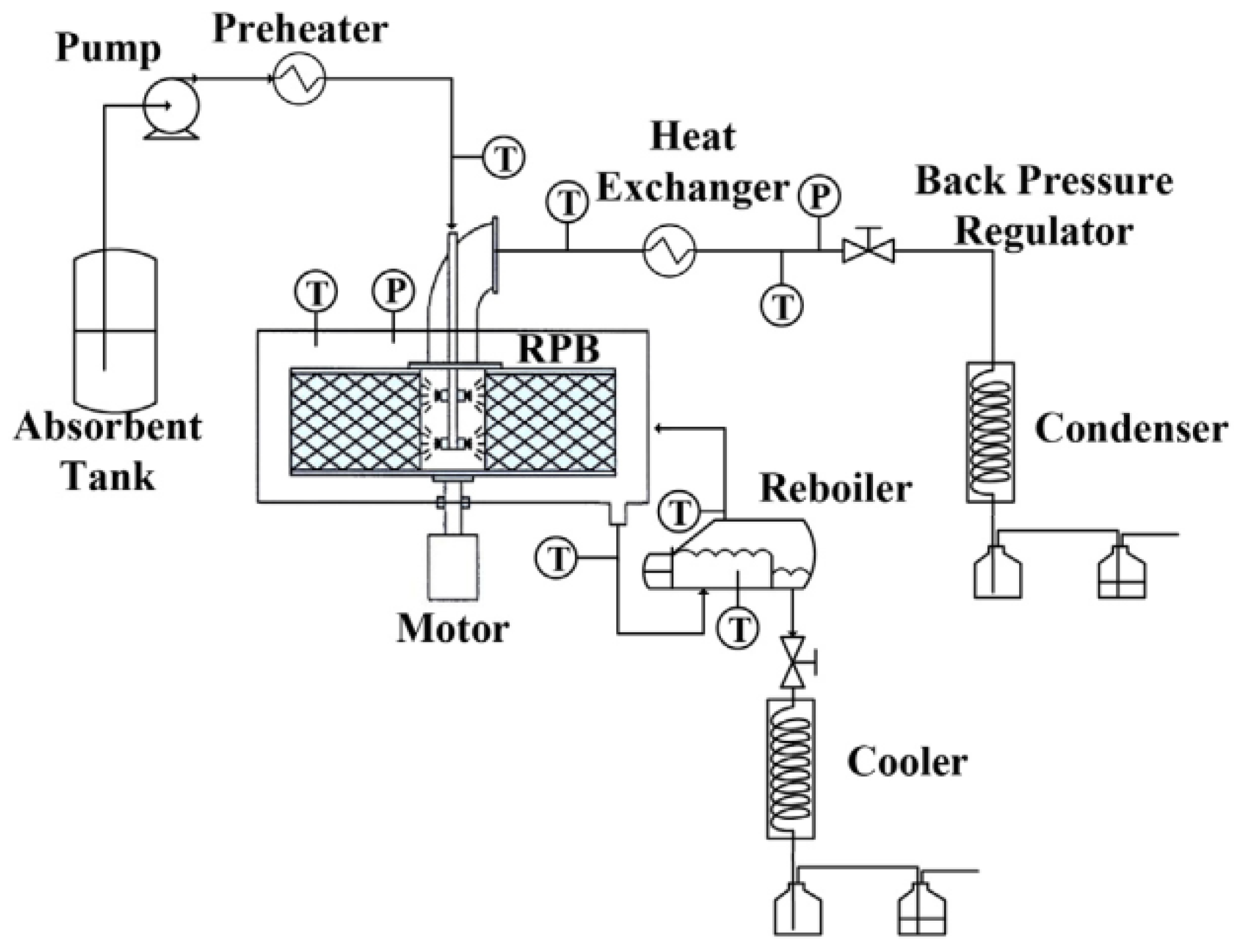
3.4. Rotating Packed Bed (RPB)

Rotating packed bed (RPB) has gained attention for the potential of process intensification in CO2 separation. RPB was invented by Ramshaw and Mallinson in 1981 to intensify the mass transfer process, compared to the conventional packed bed [84]. As the conventional packed bed in real industry application faced several challenges, such as a large footprint and low mass transfer coefficient, several studies have been conducted on RPB for the potential of replacing the packed bed in the post-combustion application. The RPB was developed to reduce the column size and the complexity of the CO2 absorption plant. Ramshaw reported that the RPB provides a volume of reduction by 2–3 orders of magnitude; additionally, the height equivalent of a theoretical plate (HETP) of RPB can be as low as 1–2 cm, when compared to the conventional packed-bed column [85].
In the typical RPB for the desorption process, the rich solvent flows through a rotating packed bed from the middle part of the RPB and is distributed through the thin liquid films generated by the centrifuge force, which leads to a greater mass transfer [86]. In addition to the absorption and desorption processes, the RPB has been used in distillation and material production. Figure 8 illustrates the cross-section of the RPB for the desorption process. The standard counter-current RPB is equipped with the casing, liquid solvent distributor, dynamic seal, and rotor shaft with the packing. The liquid solvent enters the RPB via the liquid inlet and is distributed in the packed-bed section. Then, the solvent is pushed out from the packed bed by the centrifugal force. The lean solvent is later collected at the bottom section of the RPB. Meanwhile, the gas flows inward to the packed bed and leaves the RPB through the central section, as shown in Figure 9. A reboiler is required to heat the solvent for a better desorption process rate.
Atuman et al. performed simulation work to study the size reduction in the RPB, compared to the conventional packed bed [87]. This simulation was validated using an experimental study conducted by Jasim et al. [88]. The simulation study of the CO2 desorption process from MEA was conducted under some fixed conditions, such as rich-MEA solvent flow rate (0.3 kg/s), temperature (104 °C), pressure (202 kPa), and solvent loading (0.482 mol CO2/mol MEA) for both the RPB and conventional packed bed. It was found that the packing volume for the RPB was 0.015 m3, while the conventional packed bed was 0.659. The results show that there is a 44 times reduction in the packing volume for the RPB, compared to the conventional packed bed. Additionally, the calculated height of the transfer unit for the RPB is 1.7 cm, while the conventional packed bed is 20.8 cm. This result contributes to the smaller size of the RPB, compared to the conventional packed bed [87]. Based on the finding by Agarwal et al., the casing volume of the RPB and the packed bed was 4.5 times its packing volume [89]. Hence, the overall volume of the RPB is concluded to be 9.7 times smaller than the conventional packed bed.
The RPB is also known as the energy-intensive system for the solvent regeneration process. The regeneration energy refers to three types of heat required during the desorption or solvent regeneration process, which are the heat of the reaction with CO2, the sensible heat of the solution, and the heat of vaporization. For the energy reduction strategy, these three types of energy should be minimized to as low as possible. The heat of the reaction with CO2 can be adjusted through the heat energy required for the thermal liquid solvent regeneration. Meanwhile, the sensible heat of the solution and the heat of vaporization can be reduced via the optimization of process conditions with a good process design [90]. Apart from these three types of heat required during generation, the reboiler energy and the power of the rotor rotation are crucial to be included for the overall energy consumption.
Chamchan developed a model to study the energy consumption for conventional packed bed and RPB which have been validated from pilot plat at China Steel Corporation (CSC) [91]. This packed-bed pilot plant was equipped with 16mm of packed SUS pall ring, where the diameter of the packed-bed column was 0.1 m with a 2 m height. Meanwhile, the RPB has a 0.06 m height, 0.36 m outer diameter, and 0.12 m inner diameter, which use a 5428 cm3 wire-mesh packing volume. The comparable energy consumption for the conventional packed bed and RPB were obtained using an ASPEN Plus Rate-Based model. The authors found that the energy consumption for the RPB was slightly higher than the packed bed. The RPB consumed about 7.5 GJ/tons of CO2, while the packed bed consumed about 6.5 GJ/tons of CO2 for the regeneration of the MEA solvent [91]. Additionally, Tan and Chen performed a study to identify the power consumption rate for the RPB by using the equation developed by Singh et al. [92]. The results from the study showed that 1.2 kW of power was required for the flow rate of 90 cm3/min. However, this power consumption value is unacceptable for a techno-economy CO2-removal process [93]. Thiels et al. proposed to combine the RPB with a packed-bed column as a method to reduce the energy consumption of the RPB [94].

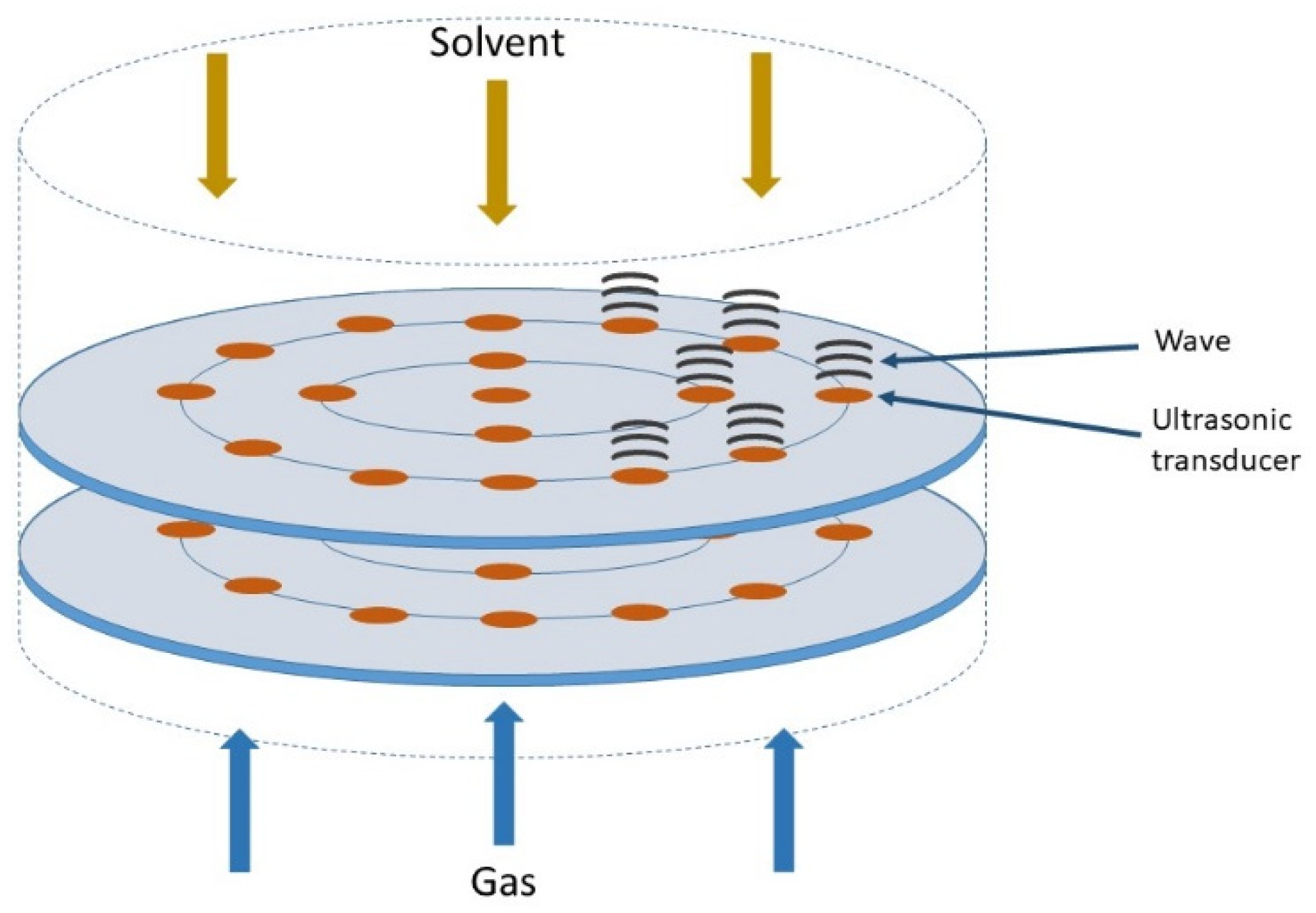
3.5. Ultrasonic Irradiation

Recently, ultrasonic irradiation has been found to be a potential alternative for a high mass transfer rate without having any moving part [95,96]. This advantage was applied to the gas–liquid absorption and desorption process. Ultrasonic irradiation is a sound wave that has a higher frequency (20 kHz to 500 MHz) than the limit that can be heard by human beings. Furthermore, the ultrasonic irradiation is usually used to enhance the gas–liquid phase reaction mostly involving the physical kinetic effect, as it can produce chemical and physical effects on the liquid phase. In the natural gas purification process, especially in the desorption process, the ultrasonic wave is able to perform the cavitation and nucleation in the liquid solvent and leads to the bubble’s formation. The gas diffuses in these bubbles and causes the sour gas to escape through the bubbles. The more bubbles that are created, the higher the occurrence of the gas desorption rate. The cavitation effect is more favorable for the desorption process rather than the absorption process, which relies on the atomization and the fountain effect from the solvent vibration [97]. Hence, the development of ultrasonic columns for desorption or solvent regeneration always fulfilled the cavitation effect.
The cavitation effect is typically produced by a low frequency of ultrasonic irradiation [98,99]. The cavitation or the bubble formation can only be produced under the rarefaction phase of the ultrasonic irradiation [100]. A stable microbubble formation is required to improve the desorption process, which can either be stable at a certain average formation size in a many-cycle rate when growing and exploding, or collapse during the ultrasound wave compression [101,102,103,104,105]. Based on this theory, the desorption or the degassing process could be further improved using ultrasonic irradiation. Figure 9 shows the ultrasonic irradiation column for the gas purification adapted from a study by Tay et al. [106].
Figure 9. Ultrasonic irradiation column [106].
Sustainability 14 04350 g009
The concept of using ultrasonic irradiation can be used to enhance the desorption rate as well as the desorption capacity of the flue gas, which is due to the high mass transfer contributed to by the physical kinetic effect in the liquid phase. Several studies proved that ultrasonic irradiation has the potential to improve the mass transfer process during the desorption process [107,108,109]. Jiru Ying et al. conducted a study to investigate the effect of ultrasound on the CO2 desorption from a 30 wt% MEA solvent using a 28 kHz ultrasonic transducer [110]. The authors found that the desorption rate of CO2 increased as they introduced the ultrasound, compared to the CO2 desorption from the heating treatment. The desorption rate of CO2 was measured in terms of the CO2 flow rate vented from the vessel using a flow meter. The flow rate of CO2 desorption measured in the presence of ultrasonic irradiation was 1.51 g/min, while the flow rate of CO2 desorption measured with the usage of heating treatment was 0.30 g/min. The results show that ultrasonic irradiation can enhance the desorption rate by about 5 times, when compared to the direct heating process. This was due to the fact that more bubbles are formed in the vessel equipped with the ultrasonic wave, which remarkably provides a large surface area for the gas–liquid contact area [111]. Moreover, this study also indicated that the ultrasonic irradiation could reduce the energy consumption for the CO2 desorption, as it did not require any heating duty. However, the other energy consumed, such as electrical energy, needs to be considered to prove the power reduction during the CO2 desorption, while using the ultrasonic irradiation.
Additionally, S. Gantert and D. Moller [112] performed a study on power consumption during the CO2 desorption in a batch reactor. The study focused on the desorption of CO2 from 30 wt% of MEA and compared multiple ultrasonic intensities (10–50 W) with the same ultrasonic frequency. The authors found that the highest ultrasonic intensity, which was 50W, produced the highest CO2 desorption flow rate (3.2 × 10⁻² m3/s). This indicates that the highest intensity of ultrasonic irradiation led to the highest amount of bubble formation. Additionally, no desorption process occurs at 40 °C, while desorption starts to occur at the temperature of 45 °C, and achieved the peak level at 80 °C. The typical packed column required 100–120 °C to initiate the desorption process [113]; hence, ultrasonic irradiation is capable of reducing the energy consumption during the desorption process. As a low temperature (80 °C) is required to initiate the process, the degradation of MDEA can also be reduced. Davis and Rochelle reported that the degradation of MEA is reduced by a factor of 4 when decreasing the temperature for every 17 °C [114].
To date, several researchers tried to perform a study to reduce the footprint of the desorption column. A small footprint of the desorption column is essential, especially for the offshore natural gas purification process, due to the space limitation. Based on the previous works [97], the intensification factor for ultrasonic irradiation can be high, up to 16 times, compared to the packed-bed column. Due to this, this technology can also be used with a slow kinetic solvent, such as MDEA. Typically, the commercial ultrasonic transducer disc is only about 2 mm thick, which contributes to the minimal footprint requirement for a single ultrasonic vessel. Due to the compact and simpler design, the manufacturing cost for the ultrasonic irradiation column is believed to be less, which is mainly contributed to by the vessel body, piezoelectric ultrasound transducer, and the power supply [115].

4. Advantages and Challenges of the Emerging Regeneration Technologies for the Offshore Natural Gas Purification Process

The offshore natural gas purification process should be energy efficient and compact. In order to fulfill these requirements, various emerging solvent regeneration processes have been established. Table 2 shows the comparative analysis of the emerging solvent regeneration technologies for the offshore natural purification process, in terms of the energy consumption and size reduction. As a summary, membrane contactor technology is the most promising emerging solvent regeneration technology, since this form of technology can significantly reduce the energy consumption and footprint requirements, followed by ultrasonic irradiation technology, microwave, and rotating packed-bed technology. Yet, all these emerging technologies suffer from several drawbacks in terms of their operational and maintenance difficulties, and material reliability. To ensure the feasibility of these technologies, these highlighted issues should be addressed prior to their full commercial application.

5. Conclusions

The choice of CO2 capture technology heavily depends on CO2 partial pressure, energy consumption, footprint requirement, and the targeted quality of the gas product. These factors are crucial to be considered in offshore applications. CO2 separation via absorption is widely used in the industry, due to its capability to be operated under a broad range of CO2 compositions and lower hydrocarbon losses. Despite being the most mature form of technology, the application of absorption for the offshore natural gas purification process is hindered by a high solvent regeneration energy and excessive footprint requirement. The development of emerging regeneration technologies in CO2 capture, such as membrane contactor, flash drum, rotating packed bed, microwave heating, and ultrasonic irradiation, contributed to the closure of these technology gaps. Generally, the conventional technologies, such as the packed column and flash drum, produce a large footprint and tonnage, which restrict their application in the offshore natural gas purification process. The RPB column and microwave heating demonstrate a higher solvent flexibility and process stability, but suffer from extensive maintenance and high regeneration energy. The membrane contactor and ultrasonic irradiation absorption system are compact, yet their application in the offshore natural gas purification process is constrained by various operational issues. Thus, future research is necessary to fully comprehend the viability of these technologies for achieving the most efficient process for solvent regeneration through the offshore natural gas purification process.

Author Contributions

Conceptualization, K.K.L., M.M.M.P. and N.A.; writing—original draft preparation, K.K.L., M.M.M.P. and N.A.; writing—review and editing, K.K.L.; supervision, K.K.L.; funding acquisition, K.K.L., M.M.M.P. and N.A. All authors have read and agreed to the published version of the manuscript.

Funding

This research was funded by Yayasan Universiti Teknologi PETRONAS, grant number 015LC0-121.

Institutional Review Board Statement

Not applicable.

Informed Consent Statement

Not applicable.

Data Availability Statement

Not applicable.

Acknowledgments

The authors would like to acknowledge Universiti Teknologi PETRONAS for the facilities provided.

Conflicts of Interest

The authors declare no conflict of interest.

References

  1. Fang, D.; Zhang, X.; Yu, Q.; Jin, T.C.; Tian, L. A novel method for carbon dioxide emission forecasting based on improved Gaussian processes regression. J. Clean. Prod. 2018, 173, 143–150. [Google Scholar] [CrossRef]
  2. Fong, W.K.; Matsumoto, H.; Ho, C.S.; Lun, Y.F. Energy Consumption and Carbon Dioxide Emission Consideration in the Urban Planning Process in Malaysia. J. Malays. Inst. Plan. 2008, 6, 99–128. [Google Scholar]
  3. Dehghani-Sanij, A.; Bahadori, M.N. Energy consumption and environmental consequences. In Ice-Houses; Elsevier: Berlin, Germany, 2021; pp. 1–55. [Google Scholar]
  4. Archer, D.; Eby, M.; Brovkin, V.; Ridgwell, A.; Cao, L.; Mikolajewicz, U.; Caldeira, K.; Matsumoto, K.; Munhoven, G.; Montenegro, A.; et al. Atmospheric Lifetime of Fossil Fuel Carbon Dioxide. Annu. Rev. Matsumoto Planet. Sci. 2009, 37, 117–134. [Google Scholar] [CrossRef] [Green Version]
  5. Sreenivasulu, B.; Gayatri, D.V.; Sreedhar, I.; Raghavan, K.V. A journey into the process and engineering aspects of carbon capture technologies. Renew. Sustain. Energy Rev. 2015, 41, 1324–1350. [Google Scholar] [CrossRef]
  6. International Energy Agency (IEA). Global Energy-Related CO2 Emissions, 1990–2020. 2021. Available online: https://www.iea.org/data-and-statistics/charts/global-energy-related-co2-emissions-1990-2020 (accessed on 14 March 2022).
  7. Nicola, M.; Alsafi, Z.; Sohrabi, C.; Kerwan, A.; Al-Jabir, A.; Iosifidis, C.; Agha, M.; Agha, R. The socio-economic implications of the coronavirus pandemic (COVID-19): A review. Int. J. Surg. 2020, 78, 185–193. [Google Scholar] [CrossRef] [PubMed]
  8. Tan, C.H.; Ong, M.Y.; Nomanbhay, S.M.; Shamsuddin, A.H.; Show, P.L. The influence of COVID-19 on global CO2 emissions and climate change: A perspective from Malaysia. Sustainability 2021, 13, 8461. [Google Scholar] [CrossRef]
  9. Moazzem, S.; Rasul, M.G.; Khan, M.M.K. A Review on Technologies for Reducing CO2 Emission from Coal Fired Power Plants; IntechOpen: London, UK, 2012. [Google Scholar]
  10. U.S. Energy Information Administration. Administration, International Energy Statistics; Energy Information Administration: Washington, DC, USA, 2016. [Google Scholar]
  11. Lallemand, F.; Lecomte, F.; Streicher, C. Highly Sour Gas Processing: H2S Bulk Removal with the Sprex Process. In Proceedings of the International Petroleum Technology Conference, Doha, Qatar, 21–23 November 2005. [Google Scholar] [CrossRef]
  12. Global CCS Institute. The Global Status of CCS: 2014; Global CCS Institute: Docklands, Australia, 2014. [Google Scholar]
  13. Mondal, M.K.; Balsora, H.K.; Varshney, P. Progress and trends in CO2 capture/separation technologies: A review. Energy 2012, 46, 431–441. [Google Scholar] [CrossRef]
  14. Zhang, Z.; Wang, H.; Chen, X.; Xie, R.; Gao, P.; Wei, W.; Sun, Y. CO2 sorption in wet ordered mesoporous silica kit-6: Effects of water content and mechanism on enhanced sorption capacity. Adsorption 2014, 7, 883–888. [Google Scholar] [CrossRef]
  15. Girimonte, R.; Testa, F.; Gallo, M.; Buscieti, R.; Leone, G.; Formisani, B. Adsorption of CO2 on Amine-Modified Silica Particles in a Confined-Fluidized Bed. Processes 2020, 8, 1531. [Google Scholar] [CrossRef]
  16. Valverde, J.M.; Medina, S. Reduction of Calcination Temperature in the Calcium Looping Process for CO2 Capture by Using Helium: In Situ XRD Analysis. ACS Sustain. Chem. Eng. 2016, 4, 7090–7097. [Google Scholar] [CrossRef]
  17. Ma, Z.W.; Zhang, P.; Bao, H.S.; Deng, S. Review of fundamental properties of CO2 hydrates and CO2 capture and separation using hydration method. Renew. Sustain. Energy Rev. 2016, 53, 1273–1302. [Google Scholar] [CrossRef]
  18. Songolzadeh, M.; Soleimani, M.; Takht Ravanchi, M.; Songolzadeh, R. Carbon Dioxide Separation from Flue Gases: A Technological Review Emphasizing Reduction in Greenhouse Gas Emissions. Sci. World J. 2014, 2014, 828131. [Google Scholar] [CrossRef] [Green Version]
  19. Han, Y.; Yang, Y.; Ho, W.S. Recent progress in the engineering of polymeric membranes for CO2 capture from flue gas. Membranes 2020, 10, 365. [Google Scholar] [CrossRef] [PubMed]
  20. Li, B.; Duan, Y.; Luebke, D.; Morreale, B. Advances in CO2 capture technology: A patent review. Appl. Energy 2013, 102, 1439–1447. [Google Scholar] [CrossRef]
  21. Powell, C.E.; Qiao, G.G. Polymeric CO2/N2 gas separation membranes for the capture of carbon dioxide from power plant flue gases. J. Memb. Sci. 2006, 279, 1–49. [Google Scholar] [CrossRef]
  22. El-Azzami, L.A.; Grulke, E.A. Carbon dioxide separation from hydrogen and nitrogen by fixed facilitated transport in swollen chitosan membranes. J. Memb. Sci. 2008, 323, 225–234. [Google Scholar] [CrossRef]
  23. Olajire, A.A. CO2 capture and separation technologies for end-of-pipe applications—A review. Energy 2010, 35, 2610–2628. [Google Scholar] [CrossRef]
  24. Berstad, D.; Anantharaman, R.; Nekså, P. Low-temperature CO2 capture technologies—Applications and potential. Int. J. Refrig. 2013, 36, 1403–1416. [Google Scholar] [CrossRef]
  25. Leung, D.Y.C.; Caramanna, G.; Maroto-Valer, M.M. An overview of current status of carbon dioxide capture and storage technologies. Renew. Sustain. Energy Rev. 2014, 39, 426–443. [Google Scholar] [CrossRef] [Green Version]
  26. Cannone, S.F.; Lanzini, A.; Santarelli, M. A Review on CO2 Capture Technologies with Focus on CO2-Enhanced Methane Recovery from Hydrates. Energies 2021, 14, 387. [Google Scholar] [CrossRef]
  27. Zhou, X.; Zang, X.; Long, Z.; Liang, D. Multiscale analysis of the hydrate based carbon capture from gas mixtures containing carbon dioxide. Sci. Rep. 2021, 11, 9197. [Google Scholar] [CrossRef] [PubMed]
  28. Yang, M.; Song, Y.; Liu, W.; Zhao, J.; Ruan, X.; Jiang, L.; Li, Q. Effects of additive mixtures (THF/SDS) on carbon dioxide hydrate formation and dissociation in porous media. Chem. Eng. Sci. 2013, 90, 69–76. [Google Scholar] [CrossRef]
  29. Hasan, S.; Abbas, A.J.; Nasr, G.G. Improving the Carbon Capture Efficiency for Gas Power Plants through Amine-Based Absorbents. Sustainability 2020, 13, 72. [Google Scholar] [CrossRef]
  30. Cormos, C.-C. IGCC with Carbon Capture and Storage. Encycl. Sustain. Technol. 2017, 327–338. [Google Scholar] [CrossRef]
  31. Luis, P. Use of monoethanolamine (MEA) for CO2 capture in a global scenario: Consequences and alternatives. Desalination 2016, 380, 93–99. [Google Scholar] [CrossRef] [Green Version]
  32. Yu, C.H.; Huang, C.H.; Tan, C.S. A review of CO2 capture by absorption and adsorption. Aerosol Air Qual. Res. 2012, 12, 745–769. [Google Scholar] [CrossRef] [Green Version]
  33. Pellegrini, L.A.; Gilardi, M.; Giudici, F.; Spatolisano, E. New Solvents for CO2 and H2S Removal from Gaseous Streams. Energies 2021, 14, 6687. [Google Scholar] [CrossRef]
  34. Sarmad, S.; Mikkola, J.P.; Ji, X. Carbon Dioxide Capture with Ionic Liquids and Deep Eutectic Solvents: A New Generation of Sorbents. ChemSusChem 2017, 10, 324–352. [Google Scholar] [CrossRef]
  35. Ramdin, M.; de Loos, T.W.; Vlugt, T.J. State-of-the-Art of CO2 Capture with Ionic Liquids. Ind. Eng. Chem. Res. 2012, 51, 8149–8177. [Google Scholar] [CrossRef]
  36. Zeng, S.; Zhang, X.; Bai, L.; Zhang, X.; Wang, H.; Wang, J.; Bao, D.; Li, M.; Liu, X.; Zhang, S. Ionic-Liquid-Based CO2 Capture Systems: Structure, Interaction and Process. Chem. Rev. 2017, 117, 9625–9673. [Google Scholar] [CrossRef]
  37. Ma, C.; Sarmad, S.; Mikkola, J.P.; Ji, X. Development of Low-Cost Deep Eutectic Solvents for CO2 Capture. Energy Procedia 2017, 142, 3320–3325. [Google Scholar] [CrossRef]
  38. Haghbakhsh, R.; Raeissi, S. Deep eutectic solvents for CO2 capture from natural gas by energy and exergy analyses. J. Environ. Chem. Eng. 2019, 7, 103411. [Google Scholar] [CrossRef]
  39. Rufford, T.E.; Smart, S.; Watson, G.C.; Graham, B.F.; Boxall, J.; Da Costa, J.D.; May, E.F. The removal of CO2 and N2 from natural gas: A review of conventional and emerging process technologies. J. Pet. Sci. Eng. 2012, 94–95, 123–154. [Google Scholar] [CrossRef]
  40. Hussin, F.; Aroua, M.K. Recent trends in the development of adsorption technologies for carbon dioxide capture: A brief literature and patent reviews (2014–2018). J. Clean. Prod. 2020, 253, 119707. [Google Scholar] [CrossRef]
  41. Kárászová, M.; Zach, B.; Petrusová, Z.; Červenka, V.; Bobák, M.; Šyc, M.; Izák, P. Post-combustion carbon capture by membrane separation. Review. Sep. Purif. Technol. 2020, 238, 116448. [Google Scholar] [CrossRef]
  42. Ali, A.; Maqsood, K.; Syahera, N.; Shariff, A.B.; Ganguly, S. Energy Minimization in Cryogenic Packed Beds during Purification of Natural Gas with High CO2 Content. Chem. Eng. Technol. 2014, 37, 1675–1685. [Google Scholar] [CrossRef]
  43. Choi, W.-J.; Seo, J.-B.; Jang, S.-Y.; Jung, J.-H.; Oh, K.-J. Removal characteristics of CO2 using aqueous MEA/AMP solutions in the absorption and regeneration process. J. Environ. Sci. 2009, 21, 907–913. [Google Scholar] [CrossRef]
  44. Chen, P.C.; Lin, S.Z. Optimization in the Absorption and Desorption of CO2 Using Sodium Glycinate Solution. Appl. Sci. 2018, 8, 2041. [Google Scholar] [CrossRef] [Green Version]
  45. Ziobrowski, Z.; Rotkegel, A. Comparison of CO2 Separation Efficiency from Flue Gases Based on Commonly Used Methods and Materials. Materials 2022, 15, 460. [Google Scholar] [CrossRef]
  46. Desideri, U. Advanced absorption processes and technology for carbon dioxide (CO2) capture in power plants. In Developments and Innovation in Carbon Dioxide (CO2) Capture and Storage Technology; Elsevier: Berlin, Germany, 2010; pp. 155–182. [Google Scholar]
  47. Nanda, S.; Reddy, S.N.; Mitra, S.K.; Kozinski, J.A. The progressive routes for carbon capture and sequestration. Energy Sci. Eng. 2016, 4, 99–122. [Google Scholar] [CrossRef] [Green Version]
  48. Liang, Z.H.; Rongwong, W.; Liu, H.; Fu, K.; Gao, H.; Cao, F.; Zhang, R.; Sema, T.; Henni, A.; Sumon, K.; et al. Recent progress and new developments in post-combustion carbon-capture technology with amine based solvents. Int. J. Greenh. Gas Control. 2015, 40, 26–54. [Google Scholar] [CrossRef] [Green Version]
  49. Chu, F.; Su, M.; Yang, G. Effects of stripper configurations on mass transfer and energy consumption of regeneration process. Int. J. Low-Carbon Technol. 2020, 15, 190–201. [Google Scholar] [CrossRef]
  50. Vadillo, J.M.; Gomez-Coma, L.; Garea, A.; Irabien, A. Hollow Fiber Membrane Contactors in CO2 Desorption: A Review. Energy Fuels 2021, 35, 111–136. [Google Scholar] [CrossRef]
  51. Zhang, Z.E.; Yan, Y.F.; Zhang, L.; Ju, S.X. Hollow fiber membrane contactor absorption of CO2 from the flue gas: Review and perspective. Glob. Nest J. 2014, 16, 355–374. [Google Scholar] [CrossRef] [Green Version]
  52. Klaassen, R.; Feron, P.H.M.; Jansen, A.E. Membrane contactors in industrial applications. Chem. Eng. Res. Des. 2005, 83, 234–246. [Google Scholar] [CrossRef]
  53. Giorno, L.; Drioli, E.; Strathmann, H.; Cosenza, R. Encyclopedia of Membranes; Springer: Berlin, Germany, 2015; pp. 1–6. [Google Scholar] [CrossRef]
  54. Scholes, C.A.; deMontigny, D.; Kentish, S.E.; Stevens, G.W. Regenerating Membrane Contactors for Solvent Absorption. Energy Procedia 2017, 114, 642–649. [Google Scholar] [CrossRef]
  55. Takahashi, N.; Matsuzaki, K.; Funai, T.; Wada, T.; Fukunaga, H.; Takatsuka, T.; Mano, H. Effects of Membrane Properties on CO2 Desorption from Chemical Absorbents Using a Membrane Flash Process. Energy Procedia 2013, 37, 1060–1066. [Google Scholar] [CrossRef] [Green Version]
  56. Lu, J.-G.; Zheng, Y.-F.; Cheng, M.-D. Wetting mechanism in mass transfer process of hydrophobic membrane gas absorption. J. Memb. Sci. 2008, 308, 180–190. [Google Scholar] [CrossRef]
  57. Yu, X.; An, L.; Yang, J.; Tu, S.T.; Yan, J. CO2 capture using a superhydrophobic ceramic membrane contactor. J. Memb. Sci. 2015, 496, 1–12. [Google Scholar] [CrossRef]
  58. Lv, Y.; Yu, X.; Tu, S.T.; Yan, J.; Dahlquist, E. Wetting of polypropylene hollow fiber membrane contactors. J. Memb. Sci. 2010, 362, 444–452. [Google Scholar] [CrossRef]
  59. Wang, R.; Zhang, H.Y.; Feron, P.H.M.; Liang, D.T. Influence of membrane wetting on CO2 capture in microporous hollow fiber membrane contactors. Sep. Purif. Technol. 2005, 46, 33–40. [Google Scholar] [CrossRef]
  60. Franco, J.; Demontigny, D.; Kentish, S.; Perera, J.; Stevens, G. A Study of the Mass Transfer of CO2 through Different Membrane Materials in the Membrane Gas Absorption Process. Sep. Sci. Technol. 2008, 43, 225–244. [Google Scholar] [CrossRef]
  61. Scholes, C.A.; Kentish, S.E.; Stevens, G.W.; deMontigny, D. Comparison of thin film composite and microporous membrane contactors for CO2 absorption into monoethanolamine. Int. J. Greenh. Gas Control. 2015, 42, 66–74. [Google Scholar] [CrossRef]
  62. Hoff, K.A.; Juliussen, O.; Falk-Pedersen, O.; Svendsen, H.F. Modeling and Experimental Study of Carbon Dioxide Absorption in Aqueous Alkanolamine Solutions Using a Membrane Contactor. Ind. Eng. Chem. Res. 2004, 43, 4908–4921. [Google Scholar] [CrossRef]
  63. Mavroudi, M.; Kaldis, S.P.; Sakellaropoulos, G.P. Reduction of CO2 emissions by a membrane contacting process☆. Fuel 2003, 82, 2153–2159. [Google Scholar] [CrossRef]
  64. Yeon, S.-H.; Sea, B.; Park, Y.-I.; Lee, K.-H. Determination of Mass Transfer Rates in PVDF and PTFE Hollow Fiber Membranes for CO2 Absorption. Sep. Sci. Technol. 2003, 38, 271–293. [Google Scholar] [CrossRef]
  65. Li, K.; Teo, W.K. Use of permeation and absorption methods for CO2 removal in hollow fibre membrane modules. Sep. Purif. Technol. 1998, 13, 79–88. [Google Scholar] [CrossRef]
  66. Nguyen, P.T.; Lasseuguette, E.; Medina-Gonzalez, Y.; Remigy, J.C.; Roizard, D.; Favre, E. A dense membrane contactor for intensified CO2 gas/liquid absorption in post-combustion capture. J. Memb. Sci. 2011, 377, 261–272. [Google Scholar] [CrossRef]
  67. Scholes, C.A.; Kentish, S.E.; Stevens, G.W.; deMontigny, D. Asymmetric composite PDMS membrane contactors for desorption of CO2 from monoethanolamine. Int. J. Greenh. Gas Control. 2016, 55, 195–201. [Google Scholar] [CrossRef]
  68. Petukhov, A.N.; Atlaskin, A.A.; Kryuchkov, S.S.; Smorodin, K.A.; Zarubin, D.M.; Petukhova, A.N.; Atlaskina, M.E.; Nyuchev, A.V.; Vorotyntsev, A.V.; Trubyanov, M.M.; et al. A highly-efficient hybrid technique—Membrane-assisted gas absorption for ammonia recovery after the Haber-Bosch process. Chem. Eng. J. 2021, 421, 127726. [Google Scholar] [CrossRef]
  69. Freeman, B.; Hao, P.; Baker, R.; Kniep, J.; Chen, E.; Ding, J.; Zhang, Y.; Rochelle, G.T. Hybrid membrane-absorption CO2 capture process. Energy Procedia 2014, 63, 605–613. [Google Scholar] [CrossRef] [Green Version]
  70. Drioli, E.; Curcio, E.; Di Profio, G. State of the art and recent progresses in membrane contactors. Chem. Eng. Res. Des. 2005, 83, 223–233. [Google Scholar] [CrossRef]
  71. Rongwong, W.; Goh, K.; Bae, T.H. Energy analysis and optimization of hollow fiber membrane contactors for recovery of dissolve methane from anaerobic membrane bioreactor effluent. J. Memb. Sci. 2018, 554, 184–194. [Google Scholar] [CrossRef]
  72. Gabelman, A.; Hwang, S.-T. Hollow fiber membrane contactors. J. Memb. Sci. 1999, 159, 61–106. [Google Scholar] [CrossRef]
  73. Hoff, K.A.; Svendsen, H.F. CO2 absorption with membrane contactors vs. packed absorbers—Challenges and opportunities in post combustion capture and natural gas sweetening. Energy Procedia 2013, 37, 952–960. [Google Scholar] [CrossRef] [Green Version]
  74. Bougie, F.; Fan, X. Analysis of the Regeneration of Monoethanolamine Aqueous Solutions by Microwave Irradiation. Energy Procedia 2017, 142, 3661–3666. [Google Scholar] [CrossRef]
  75. Microwave-assisted synthesis in Anto Paar. Available online: https://wiki.anton-paar.com/my-en/microwave-assisted-synthesis/ (accessed on 5 March 2022).
  76. Chronopoulos, T.; Fernandez-Diez, Y.; Maroto-Valer, M.M.; Ocone, R.; Reay, D.A. CO2 desorption via microwave heating for post-combustion carbon capture. Microporous Mesoporous Mater. 2014, 197, 288–290. [Google Scholar] [CrossRef]
  77. Lee, C.S.; Binner, E.; Winkworth-Smith, C.; John, R.; Gomes, R.; Robinson, J. Enhancing natural product extraction and mass transfer using selective microwave heating. Chem. Eng. Sci. 2016, 149, 97–103. [Google Scholar] [CrossRef]
  78. Cherbański, R.; Molga, E. Intensification of desorption processes by use of microwaves-An overview of possible applications and industrial perspectives. Chem. Eng. Process. Process Intensif. 2009, 48, 48–58. [Google Scholar] [CrossRef]
  79. El Khaled, D.; Novas, N.; Gázquez, J.A.; García, R.M.; Manzano-Agugliaro, F. Alcohols and alcohols mixtures as liquid biofuels: A review of dielectric properties. Renew. Sustain. Energy Rev. 2016, 66, 556–571. [Google Scholar] [CrossRef]
  80. Chowdhury, T.; Shi, M.; Hashisho, Z.; Kuznicki, S.M. Indirect and direct microwave regeneration of Na-ETS-10. Chem. Eng. Sci. 2013, 95, 27–32. [Google Scholar] [CrossRef]
  81. McGurk, S.J.; Martín, C.F.; Brandani, S.; Sweatman, M.B.; Fan, X. Microwave swing regeneration of aqueous monoethanolamine for post-combustion CO2 capture. Appl. Energy 2017, 192, 126–133. [Google Scholar] [CrossRef] [Green Version]
  82. Morales-Rodelo, K.; Álvarez, H.D. Determination and use of feasible operation region in flash distillation control. Rev. Fac. Ing. Univ. Antioquia 2020, 95, 53–63. [Google Scholar] [CrossRef]
  83. Walters, M.S.; Dunia, R.H.; Edgar, T.F.; Rochelle, G.T. Two-Stage Flash for CO2 Regeneration: Dynamic Modeling and Pilot Plant Validation. Energy Procedia 2013, 37, 2133–2144. [Google Scholar] [CrossRef] [Green Version]
  84. Mass Transfer Process. 1979. Available online: https://patentimages.storage.googleapis.com/89/6c/ce/0354b0bdbc55aa/US4283255.pdf (accessed on 15 March 2022).
  85. Ramshaw, C. Higee distillation-an example of process intensification. Chem. Eng. 1983, 389, 13–14. [Google Scholar]
  86. Zhao, H.; Shao, L.; Chen, J.-F. High-gravity process intensification technology and application. Chem. Eng. J. 2010, 156, 588–593. [Google Scholar] [CrossRef]
  87. Joel, A.S.; Wang, M.; Ramshaw, C.; Oko, E. Modelling, simulation and analysis of intensified regenerator for solvent based carbon capture using rotating packed bed technology. Appl. Energy 2017, 203, 11–25. [Google Scholar] [CrossRef] [Green Version]
  88. MJassim, M.S.; Rochelle, G.; Eimer, D.; Ramshaw, C. Carbon dioxide absorption and desorption in aqueous monoethanolamine solutions in a rotating packed bed. Ind. Eng. Chem. Res. 2007, 46, 2823–2833. [Google Scholar] [CrossRef]
  89. Agarwal, L.; Pavani, V.; Rao, D.P.; Kaistha, N. Process Intensification in HiGee Absorption and Distillation: Design Procedure and Applications. Ind. Eng. Chem. Res. 2010, 49, 10046–10058. [Google Scholar] [CrossRef]
  90. Cheng, H.H.; Lai, C.C.; Tan, C.S. Thermal regeneration of alkanolamine solutions in a rotating packed bed. Int. J. Greenh. Gas Control. 2013, 16, 206–216. [Google Scholar] [CrossRef]
  91. Chamchan, N.; Chang, J.Y.; Hsu, H.C.; Kang, J.L.; Wong, D.S.H.; Jang, S.S.; Shen, J.F. Comparison of rotating packed bed and packed bed absorber in pilot plant and model simulation for CO2 capture. J. Taiwan Inst. Chem. Eng. 2016, 73, 20–26. [Google Scholar] [CrossRef]
  92. Singh, S.P.; Wilson, J.H.; Counce, R.M.; Lucero, A.J.; Reed, G.D.; Ashworth, R.A.; Elliott, M.G. Removal of volatile organic compounds from groundwater using a rotary air stripper. Ind. Eng. Chem. Res. 1992, 31, 574–580. [Google Scholar] [CrossRef]
  93. Tan, C.-S.; Chen, J.-E. Absorption of carbon dioxide with piperazine and its mixtures in a rotating packed bed. Sep. Purif. Technol. 2006, 49, 174–180. [Google Scholar] [CrossRef]
  94. Thiels, M.; Wong, D.S.; Yu, C.-H.; Kang, J.-L.; Jang, S.S.; Tan, C.-S. Modelling and Design of Carbon Dioxide Absorption in Rotating Packed Bed and Packed Column. IFAC-PapersOnLine 2016, 49, 895–900. [Google Scholar] [CrossRef]
  95. Sutkar, V.S.; Gogate, P.R. Design aspects of sonochemical reactors: Techniques for understanding cavitational activity distribution and effect of operating parameters. Chem. Eng. J. 2009, 155, 26–36. [Google Scholar] [CrossRef]
  96. Gogate, P.R.; Pandit, A.B. Engineering design method for cavitational reactors: I. Sonochemical reactors. AIChE J. 2000, 46, 372–379. [Google Scholar] [CrossRef]
  97. Tay, W.H.; Lau, K.K.; Shariff, A.M. High frequency ultrasonic-assisted chemical absorption of CO2 using monoethanolamine (MEA). Sep. Purif. Technol. 2017, 183, 136–144. [Google Scholar] [CrossRef]
  98. Pang, Y.L.; Abdullah, A.Z.; Bhatia, S. Review on sonochemical methods in the presence of catalysts and chemical additives for treatment of organic pollutants in wastewater. Desalination 2011, 277, 1–14. [Google Scholar] [CrossRef]
  99. Doraiswamy, L.K.; Thompson, L.H. Sonochemistry:  Science and Engineering. Ind. Eng. Chem. Res. 1999, 38, 1215–1249. [Google Scholar] [CrossRef]
  100. Breitbach, M.; Bathen, D.; Schmidt-Traub, H. Effect of Ultrasound on Adsorption and Desorption Processes. Ind. Eng. Chem. Res. 2003, 42, 5635–5646. [Google Scholar] [CrossRef]
  101. Hamdaoui, O.; Naffrechoux, E. An Investigation of the Mechanisms of Ultrasonically Enhanced Desorption. AIChE J. 2007, 53, 363–373. [Google Scholar] [CrossRef]
  102. Hamdaoui, O.; Naffrechoux, E.; Tifouti, L.; Pétrier, C. Effects of Ultrasound on Adsorption–Desorption of p-Chlorophenol on Granular Activated Carbon. Ultrason. Sonochem. 2003, 10, 109–114. [Google Scholar] [CrossRef]
  103. Qin, W.; Yuan, Y.H.; Dai, Y.Y. Effect of ultrasound on desorption equilibrium. Chin. J. Chem. Eng. 2001, 9, 427–430. [Google Scholar]
  104. Hamdaoui, O.; Naffrechoux, E.; Suptil, J.; Fachinger, C. Ultrasonic desorption of p-chlorophenol from granular activated carbon. Chem. Eng. J. 2005, 106, 153–161. [Google Scholar] [CrossRef]
  105. Yu, S.; Gao, D.; Qin, Z. Ultrasonic desorption—A new regeneration technology. Int. Sugar J. 2000, 102, 202–204. [Google Scholar]
  106. Tay, W.H.; Lau, K.K.; Shariff, A.M. High frequency ultrasonic-assisted CO2 absorption in a high pressure water batch system. Ultrason. Sonochem. 2016, 33, 190–196. [Google Scholar] [CrossRef]
  107. Schueller, B.S.; Yang, R.T. Ultrasound Enhanced Adsorption and Desorption of Phenol on Activated Carbon and Polymeric Resin. Ind. Eng. Chem. Res. 2001, 40, 4912–4918. [Google Scholar] [CrossRef]
  108. Kumar, A.; Gogate, P.R.; Pandit, A.B.; Wilhelm, A.M.; Delmas, H. Investigation of induction of air due to ultrasound source in the sonochemical reactors. Ultrason. Sonochem. 2005, 12, 453–460. [Google Scholar] [CrossRef]
  109. Laugier, F.; Andriantsiferana, C.; Wilhelm, A.M.; Delmas, H. Ultrasound in gas–liquid systems: Effects on solubility and mass transfer. Ultrason. Sonochem. 2008, 15, 965–972. [Google Scholar] [CrossRef] [Green Version]
  110. Ying, J.; Eimer, D.A.; Mathisen, A.; Sørensen, H.; Haugen, H.A. Intensification of CO2 stripping from amine solutions by ultrasonic. Energy Procedia 2014, 63, 781–786. [Google Scholar] [CrossRef] [Green Version]
  111. Orhan, O.Y.; Keles, Y.; Ersan, H.Y.; Alper, E. Ultrasound-assisted Desorption of CO2 from Carbon Dioxide Binding Organic Liquids. Energy Procedia 2017, 114, 66–71. [Google Scholar] [CrossRef]
  112. Gantert, S.; Möller, D. Ultrasonic Desorption of CO2—A New Technology to Save Energy and Prevent Solvent Degradation. Chem. Eng. Technol. 2012, 35, 576–578. [Google Scholar] [CrossRef]
  113. Li, X.; Wang, S.; Chen, C. Experimental Study of Energy Requirement of CO2 Desorption from Rich Solvent. Energy Procedia 2013, 37, 1836–1843. [Google Scholar] [CrossRef] [Green Version]
  114. Davis, J.; Rochelle, G. Thermal degradation of monoethanolamine at stripper conditions. Energy Procedia 2009, 1, 327–333. [Google Scholar] [CrossRef] [Green Version]
  115. Tay, W.H.; Lau, K.K.; Lai, L.S.; Shariff, A.M.; Wang, T. Current development and challenges in the intensified absorption technology for natural gas purification at offshore condition. J. Nat. Gas Sci. Eng. 2019, 71, 102977. [Google Scholar] [CrossRef]
Figure 1. Absorption capacity of physical and chemical solvents [30].
Sustainability 14 04350 g001
Figure 2. Comparison of CO2 capture technologies (adapted data [40,41,42]).
Sustainability 14 04350 g002
Figure 3. Typical absorber–stripper configuration for the CCS system [49].
Sustainability 14 04350 g003
Figure 4. Membrane contractor configuration for separating and purifying CO2 [54].
Sustainability 14 04350 g004
Figure 5. Simplified absorption and desorption processes that have the potential to be replaced with a membrane contactor system [73].
Sustainability 14 04350 g005
Figure 6. Graphic illustration of heat induction for (a) conventional heating and (b) microwave heating (adapted from [75]).
Sustainability 14 04350 g006
Figure 7. Simplified two-stage flash process flow diagram [83].
Sustainability 14 04350 g007
Figure 8. Experimental apparatus of the rotating packed bed for solvent regeneration [90].
Sustainability 14 04350 g008
Table 1. Adaptation from the simulation results of the membrane contactor vs. packed tower [73].
ScenarioPost-Combustion CaptureNatural Gas TreatmentNatural Gas Treatment with the Presence of Promoter
Solvent used30% MEA30% MDEA30% MDEA
5% piperazine
Liquid flow modeShell sideShell sideShell side
Fiber length (meter)355
Total packed volume (m3)67552113
Volume reduction75%75%54%
Table 2. Comparison analysis between the emerging regeneration technologies.
TechnologiesEnergySizeAdvantagesDisadvantages
Membrane contactor [71,73]−85%−54%
  • High mass transfer coefficient
  • Compact size
  • Wetting and foaming issues lead to a reduction in the mass transfer
  • Short life cycle of the membrane
  • Low solvent flexibility limits the range of solvent usage
Flash drum [82,83]Not reportedNot reported
  • Less complexity, which means that it is easy to operate
  • Less maintenance needed
  • Less OPEX
  • Large footprint
  • Required a series of flash drums for better efficiency
  • Required additional systems for transferring the product
RPB [87,89,91]+115%−9.7%
  • High solvent flexibility offers a high range of solvent usage
  • High stability
  • Large regeneration energy
  • Regular maintenance due to moving parts
Ultrasonic irradiation [112,115]−66%−16%
  • High solvent flexibility offers a high range of solvent usage
  • High stability
  • Compact size
  • High mass transfer coefficient
  • High electrical energy leads to high OPEX
  • Difficulty to replace the piezoelectric transducer
Microwave [74,80,81]−16.6%−22%
  • Provide an instant heating effect
  • High solvent flexibility
  • Slow process to obtain the lean solvent
Publisher’s Note: MDPI stays neutral with regard to jurisdictional claims in published maps and institutional affiliations.

