Article

On-Site Measurement on Surface Disturbance Law of Repeated Mining with High Relief Terrain

1
State Collaborative Innovation Center of Coal Work Safety and Clean-Efficiency Utilization, Henan Polytechnic University, Jiaozuo 454003, China
2
Key Laboratory of Monitoring and Protection of Natural Resources in Mining Cities, Ministry of Natural Resources, Jinzhong 030600, China
3
Coal Geological Geophysical Exploration Surveying and Mapping Institute of Shanxi Province, Jinzhong 030600, China
*
Author to whom correspondence should be addressed.
Sustainability 2022, 14(6), 3166; https://doi.org/10.3390/su14063166
Submission received: 11 February 2022 / Revised: 4 March 2022 / Accepted: 6 March 2022 / Published: 8 March 2022

Abstract

:
Underground coal mining in high relief terrain often causes problems such as ground collapse and mountain sliding. This produces disasters such as mountain collapse and landslides, which seriously endangers the ecological environment and human settlements in the coal mining area and causes a series of public security events. To improve and solve the related problems, it is necessary to master the impact law of underground mining on ground surface. Therefore, taking the working face 1310 of Jincheng coal industry as an example, this paper adopts a new and improved RTK measurement technology for field measurement and analyzes the surface disturbance law by using field data. The results show that under the action of repeated mining in high relief terrain areas, there is a sudden subsidence in the flat bottom area of the surface moving basin, the strike influence scope is small, the dip influence scope in the downhill direction is larger, the dip horizontal movement curve loses its antisymmetry, and the dip subsidence curve loses its left-right symmetry. Through the analysis, it is found that the high reverse slope weakens the original disturbance and reduces the influence range of surface mining. On the contrary, repeated mining enhances the original disturbance, expands the influence range of surface mining, and flattens the movement deformation curve. Research results can provide a technical reference for the formulation and implementation of environmental remediation and treatment technologies in mining areas under similar conditions.

1. Introduction

China is the world’s largest coal producer, accounting for 37% of the world’s total coal output. The exploitation of underground coal resources often leads to large-scale overburden movement and surface disturbance. Surface disturbance has destroyed the original terrain, landform, and natural landscape of the mine, causing a lot of damage to land resources, water resources, and vegetation resources, and seriously damaged the living environment and ecological environment of the mining area [1,2,3,4]. This situation is particularly serious in mining areas with high relief terrain areas. The topographic relief degree of the mining area is often expressed by slope. The slope can be calculated by Formula (1).
α = arctan ( Δ H / D )
where: Δ H is the height difference and D is the horizontal distance.
According to the slope, the terrain can be divided into flat land, hilly land, mountainous land, and alpine land. The slope of flat land is less than 2°, that of hilly land is 2–6°, that of mountainous land is 6–25°, and that of alpine land is more than 25°. Mountains and alpine land are collectively referred to as high relief terrain, that is, the slope of the high relief terrain area is more than 6°.
In high relief terrain mining areas, underground mining often induces large-scale mountain sliding, large collapse cracks, and tensile cracks, which seriously damage mountains, mountain roads, buildings, structures, and water bodies. As shown in Figure 1.
At present, China is pushing the concept of “green and eco-friendly coal mining”. To promote “green and eco-friendly coal mining”, coal mining needs to be carried out within the ecological carrying capacity of the mining area. The key and prerequisite for the realization of this concept is to master the disturbance law of coal mining on the surface of the mining area.
At present, many people have conducted research on the surface subsidence monitoring in the mining area using new measurement methods, including UAV [5], 3D laser scanning [6], InSAR [7,8,9,10,11], etc., but these methods have the disadvantage that the accuracy cannot meet the engineering requirements. Therefore, traditional field measurement methods, such as leveling, traverse, and GPS are still the main methods for subsidence monitoring in the mining area.
The disturbance of coal mining to the surface is a very complex time-space movement problem under the combined action of multiple geological and topographic mining factors [12,13,14]. The same mining will show different mining effects under different geological, topographic, and mining conditions. Scholars and experts have conducted a lot of research on the mining-induced surface disturbance law under different geology, different terrain, and different mining conditions [15,16,17,18]. Among them, the more typical is the large-scale mining of coal resources under the condition of repeated mining in high relief terrain areas.
From the geological structure of mining areas, high relief terrain mines in China are widely distributed in Shanxi, Henan, Guizhou, and other provinces, accounting for more than 1/3 of the total number of mines in China. Scholars and experts have conducted in-depth research and analysis on the disturbance law of mining on the surface in high relief terrain areas.
Wang [19] and others combined AutoCAD, Surfer, and FLAC3D software to build a numerical simulation model for mining different inclined coal seams in exposed bedrock high relief terrain areas, and analyzed the influence of coal seam inclination on surface movement and deformation; Wang [20], Han [21], Lian [22], Zhao [23] and others deduced and established an improved algorithm for predicting surface subsidence in high relief terrain areas; Liu [24] constructed the surface subsidence basin model of four types of surface mountains based on the small deflection bending problem in the thin plate bending deformation theory; Dai [25], Bai [26], and Lan [27] studied the law of surface movement and deformation in high relief terrain areas in combination with model test or numerical simulation; Hu [28] and Yi [29] analyzed the damage law and mechanism of environment, ecology, ground fissures and slopes under mining conditions in high relief terrain areas.
The mining conditions in high relief terrain areas vary greatly, and the disturbance laws are also different. Limited by the mining plan and relevant policies of the mining area, the working faces in high relief terrain areas are often mined in sequence. The overburden above the working face is affected by the high relief terrain and repeated at the same time. The disturbance law of the surface above the working face is different from the traditional situation. Which not only leads to abnormal laws in the scope, degree, and location of surface disturbance, but also increases the difficulty of subsequent disturbance prediction.
Therefore, taking working face 1310 as an example, combined with the field measurement and data analysis results, this paper reveals the distribution law of surface disturbance under the comprehensive action of repeated mining in high relief terrain area.

2. Engineering Background

2.1. Basic Information of Working Face 1310

Working face 1310 is subordinate to Zhaozhuang coal mine and is located at the junction of Gaoping city and Changzi county, Shanxi province, China. The longitude is 112°48′00″~112°58′00″ E and the latitude is 35°54′00″~36°03′00″.
Coal seam 3# is the main mining coal seam of working face 1310. The ground elevation is 1012.40–1193.20 m, the maximum ground fall is nearly 200 m, the elevation of the coal seam floor is 334.00–444.00 m, the average mining depth is 760 m, the average coal seam dip angle is 3°, and the average thickness of coal seam is 4.88 m. The coal seam structure is simple, the minability coefficient is 1.0, the variation coefficient is 5.13%, and the coal seam is stable. The strike length of the working face is 2741 m and the dip length is 219.27 m. The roof control adopts all caving method. Mining method is the one-time full height mechanized mining method. The characteristics of the roof and floor strata of the working face 1310 are shown in Table 1.
Working face 1310 has the following characteristics:
① High relief terrain
The surface above the working face 1310 fluctuates greatly, as shown in Figure 2. The surface slope is steep with large drop, the maximum vertical drop can reach 200 m, and the mountain slope is about 12°. It belongs to the typical high relief terrain.
② Repeated mining
The mining sequences of the working faces in the mining area are 1308–1309–1310. The north side of working face 1310 is the planned fully mechanized mining face 1311, and the south side are fully mechanized mining faces 1308 and 1309 whose mining has been completed. In the early mining stage of working face 1310, it is affected by the residual deformation of 1308 and 1309. At the same time, working faces 1308 and 1309 are affected by the repeated mining of working face 1310, and the repeated mining disturbance is obvious.

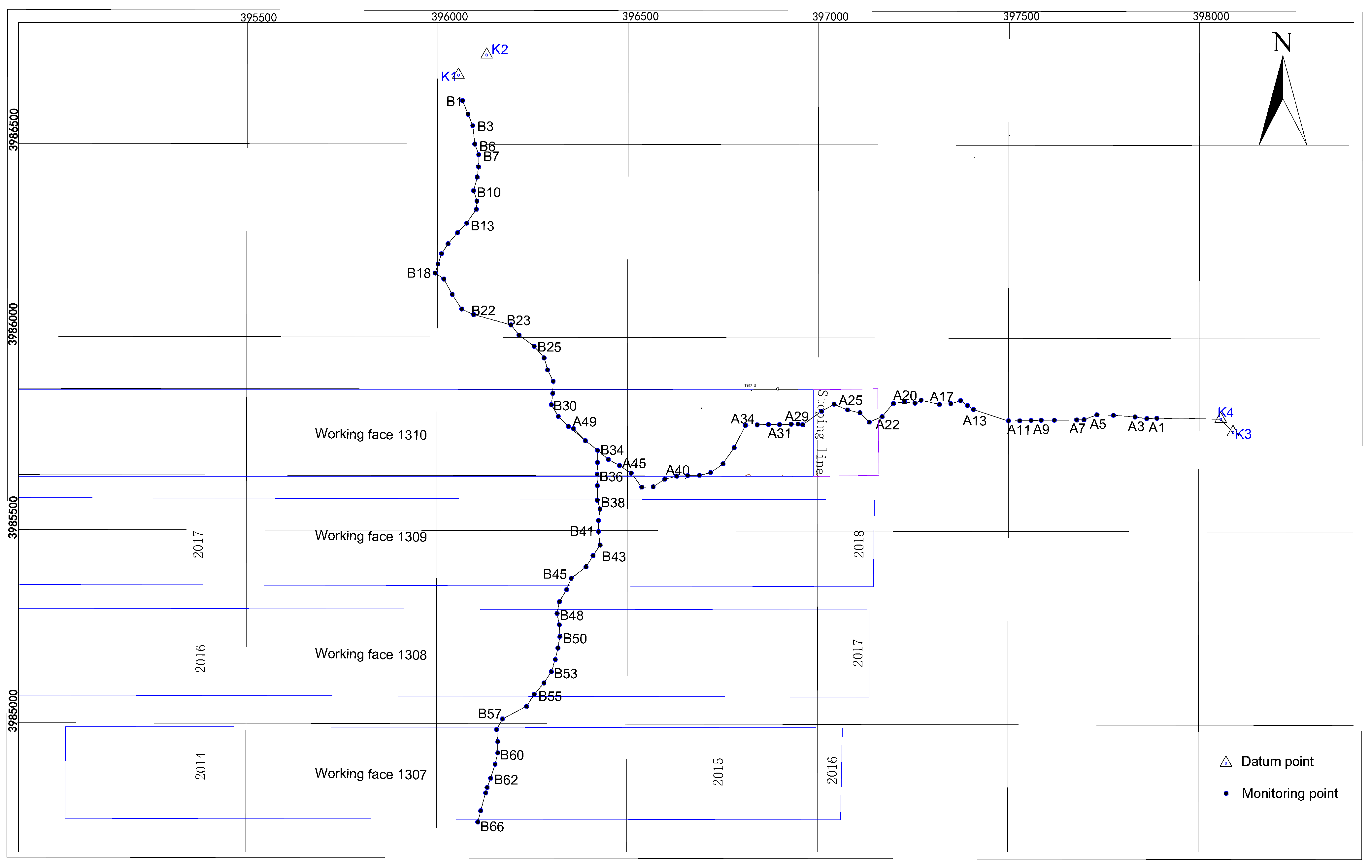
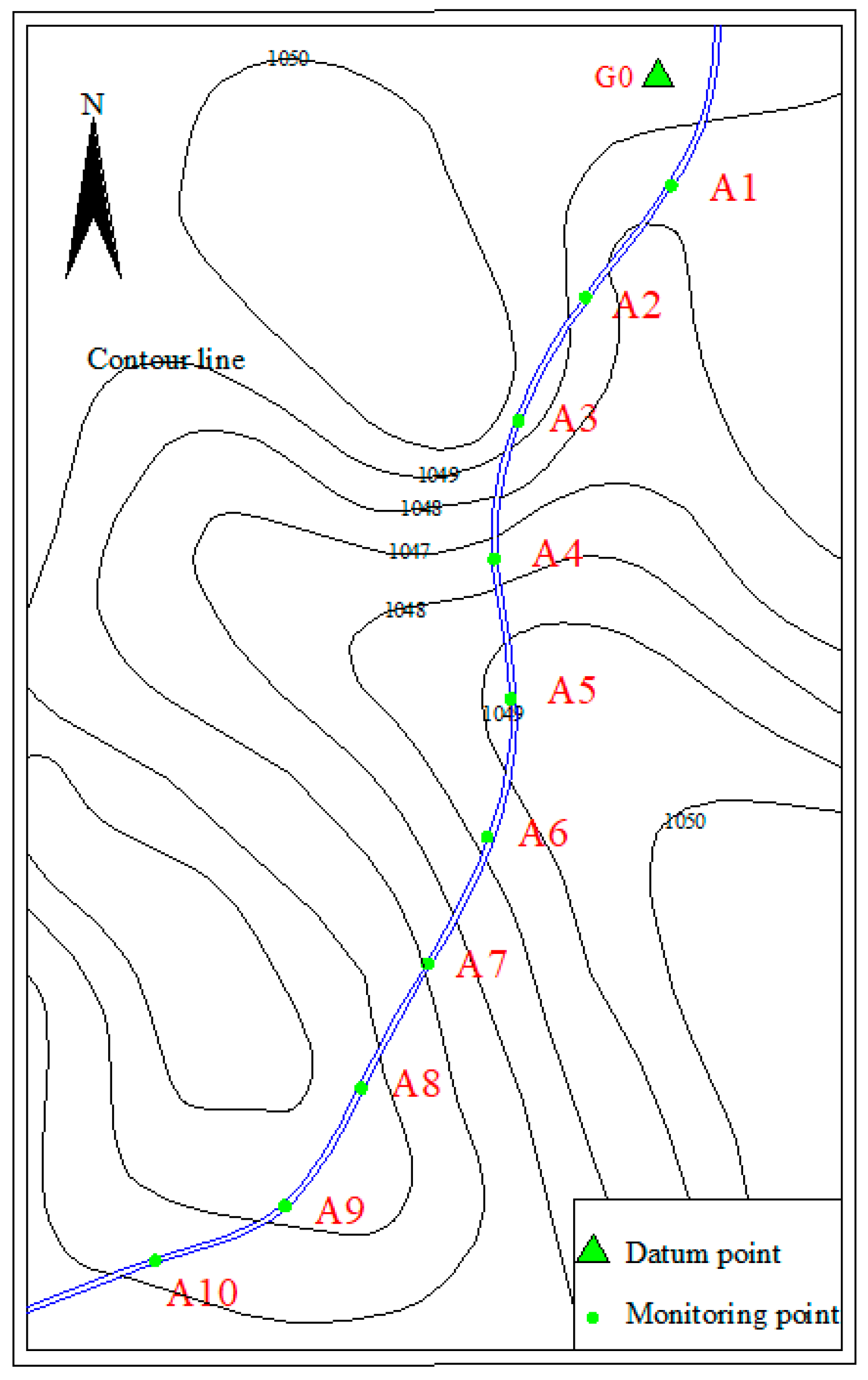
2.2. Layout of Observation Stations

According to the terrain above the working face and the code for coal mine survey, the layout of surface movement observation stations is carried out. The observation station is arranged on the side of the stopping line. The point spacing is 30 m, and half of the strike and one dip line are arranged. The information of the observation stations is shown in Figure 3 and Table 2. A total of 49 monitoring points are arranged along the strike observation line, numbered from A1 to A49, with a total length of 1440 m. A total of 66 monitoring points are arranged on the dip observation line, numbered from B1 to B66 from the downhill direction, with a total length of 1950 m

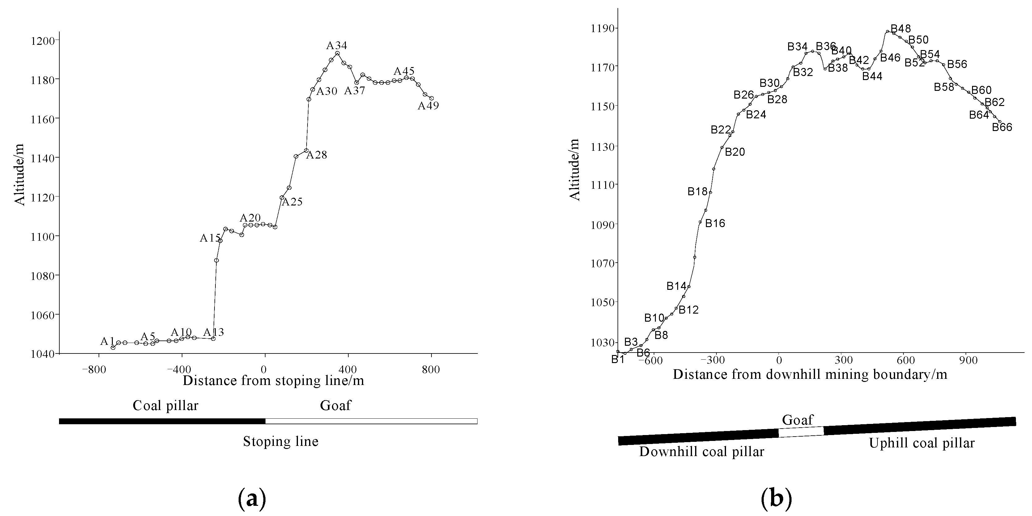
2.3. Topographic Analysis of Main Section

The topographic profile of strike and dip according to the point layout of the working face 1310 is shown in Figure 4.
Along the strike direction, surface monitoring points A1–A49 are arranged from the side of the coal pillar to the goaf. Point A22 is roughly above the stopping line. The terrain along the strike line from point A1 to point A34 generally shows an upward slope trend, with a large surface slope of about 14°. The terrain from point A34 to A49 generally shows a downhill trend. A34–A37 and A46–A49 are two steep downhill areas, with a mountain slope of about 12°.
Along the dip direction, surface monitoring points B1-B66 are set from downhill to uphill. B30 is located directly above the downhill mining boundary and B37 is located directly above the uphill mining boundary. The dip line from point B1 to point B47 generally shows an upward trend, with a slope of about 10°. The terrain from point B47 to point B66 generally shows a downward trend with a small slope of about 7°.

3. Measurement Method and Data Acquisition

3.1. Monitoring Content

The disturbance degree and scope of the surface caused by underground mining are often described by five indexes: subsidence, inclination, curvature, horizontal movement, and horizontal deformation. The subsidence and horizontal movement are the basic quantities, and the inclination, curvature and horizontal deformation are the derived quantities. The inclination and curvature can be deduced from the subsidence by Equation (2):
i 1 2 = w 2 w 1 l 1 2 k 1 2 3 = i 2 3 i 1 2 0.5 ( l 1 2 + l 2 3 )
where: w 1 and w 2 are the subsidence values of observation points 1 and 2, respectively. i 1 2 and i 2 3 are the average slopes of line segments 1–2 and 2–3, respectively. l 1 2 and l 2 3 are the horizontal lengths of segments 1–2 and 2–3, respectively. k 1 2 3 represents the curvature between observation points 1–2–3.
The horizontal deformation can be deduced from the horizontal movement by Equation (3):
ε 1 2 = u 2 u 1 l 2 3
where: ε 1 2 is the horizontal deformation between observation points 1 and 2. u 1 and u 2 are the horizontal movement values of observation points 1 and 2, respectively.
The subsidence and horizontal movement are mainly calculated by the following formula:
w i = h i 0 h i n
u i = l i 0 l i n
where, h i 0 and h i n are the elevation values of observation point i during the first and n times observations, respectively. l i 0 and l i n are the horizontal distance from point i to the control point during the first and n times observations, which can be obtained by the following formula:
l i 0 = ( x i 0 x ) 2 + ( y i 0 y ) 2 l i n = ( x i n x ) 2 + ( y i n y ) 2
where: (x, y) are the plane coordinates of the control point, x i 0 and x i n are the x coordinates of point i during the first observation and n times observations, respectively. y i 0 and y i n are the y coordinates of point i during the first observation and n times observations, respectively.
In conclusion, if the elevation h and plane coordinate values (x, y) of the observation points are measured and obtained, the subsidence and horizontal movement values can be calculated; the inclination, curvature and horizontal deformation values can be deduced to analyze the subsidence law. Therefore, the content of field monitoring mainly includes (x, y) and H.

3.2. Measuring Method

According to the accuracy requirements of mine survey regulations, RTK technology is often used to collect the plane coordinate information of observation points (x, y) and the fourth-order leveling is used to collect the H elevation data information of observation points. According to the relevant requirements, if in the area with large topographic relief, the triangular elevation method can be used to collect elevation data. Both leveling and triangular elevation require good intervisibility between observation points in the survey area. However, in the survey area, the surface topography fluctuates too much, the vegetation is dense, and the intervisibility conditions between observation points are poor, so the traditional triangular elevation and leveling cannot be carried out. Therefore, in the process of observation implementation, an improved RTK elevation acquisition method supported by cores network is proposed. The instrument adopts Southern Galaxy 6 receiver for observation.
To meet the accuracy of elevation observation. In the process of observation, the method of multiple observations is adopted, and the observation process is as follows:
① Use the triangular forced centering device to erect RTK and collect the data in the fixed solution mode. Set the sampling interval to 1 s and the sampling to 60 s to obtain the first set data of the observation point;
② Invert the RTK receiver to make it lose contact with the satellite, then put it back in the right direction and reconnect the satellite;
③ Collect the second set of data in the fixed solution mode;
④ Turn the RTK receiver upside down to make it lose contact with the satellite again, and then put it right back to reconnect the satellite;
⑤ Collect the third set data in fixed solution mode.
Then compare and analyze the three-set data. If the difference between the maximum and minimum elevation data exceeds 2 cm, remeasure it. If it is less than 2 cm, take its average value as the final value.
To verify the accuracy of this method, a verification experiment was carried out on a mountain road. The slope of the mountain road is about 10°. Select a distance of 50 m on the mountain road, take point G1 as the datum point and use the RTK survey data of point G1 as the datum elevation data to carry out leveling and RTK elevation survey. The spacing of experimental sampling points is 50 m and the number is A1–A10 (Figure 5).
This method and the fourth-order leveling method are used to measure the elevation of the experimental sampling points. The measurement results are as follows.
According to the relevant specifications, the tolerance requirements for fourth-order leveling are as follows:
ε = 12 n
The number of measured stations from each monitoring point to the datum point measured in the field is listed in Table 3. The tolerance requirement for the elevation survey of each monitoring point obtained are also listed in Table 3. By comparing the relationship between the absolute value of the elevation difference measured by the two methods and the tolerance, the following conclusions can be drawn.
(1)
The monitoring errors of monitoring points A1 and A2 (within 100 m) slightly exceed the limit;
(2)
The monitoring errors of other monitoring points are less than the tolerance and meet the accuracy requirements.
According to the requirement of mine survey code, datum points are generally buried 150–200 m outside the mining affected area. Therefore, the distance between monitoring points and datum point is greater than 100 m, that is, the improved RTK can be used for elevation measurement, and the data meet the accuracy requirements.
This new and improved RTK measurement method not only solves the problem of non-intervisibility of monitoring points in high undulating terrain area but also greatly improves the measurement speed. At the same time, the original three-person mode of leveling is changed into a one-person mode of RTK, which greatly reduces the labor intensity.

3.3. Data Acquisition

The time and contents of surface disturbance monitoring are shown in Table 4.

4. Results

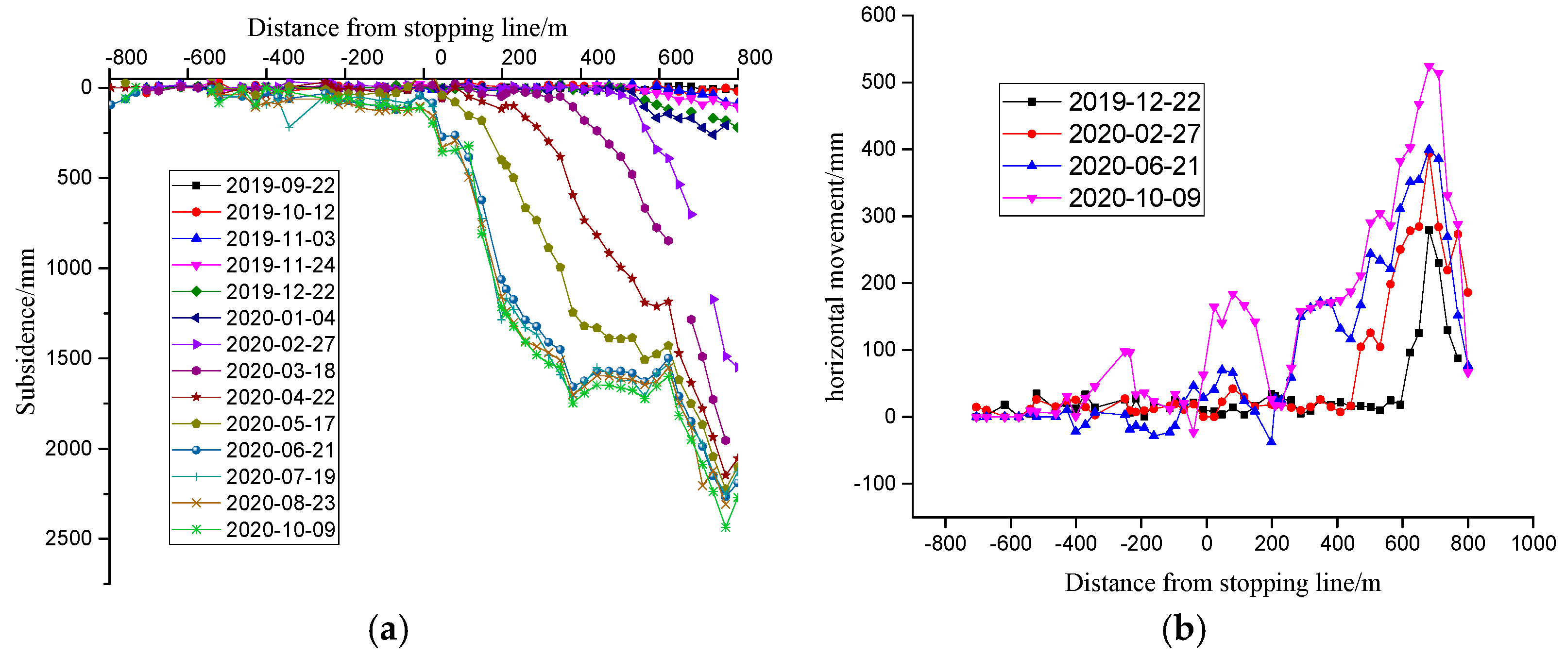
4.1. Surface Disturbance Law along Strike Direction

The data obtained in each stage of strike are processed to obtain the subsidence value and horizontal movement value. The drawing is as follows.
With the advancement of the working face, it can be seen from Figure 6a that the surface subsidence gradually increases. By 9 October 2020, a flat bottom appears within the observation range, indicating that the strike direction has reached full mining. The edge point of the flat bottom is near A35, and the maximum subsidence value is 1747 mm. However, due to the influence of high relief terrain on the inner side of the flat bottom, the flat bottom part of the surface basin has slipped again, showing serious inequality, and the maximum surface subsidence has increased to 2436 mm.
It can be seen from the Figure 6b that with the advance of the working face, the maximum value of horizontal movement in the strike direction increases and the influence range expands. However, due to the influence of high relief terrain, there are two positive extreme values of horizontal movement, among which the extreme value above the goaf is large, which is mainly the influence of high relief terrain in mountainous area.

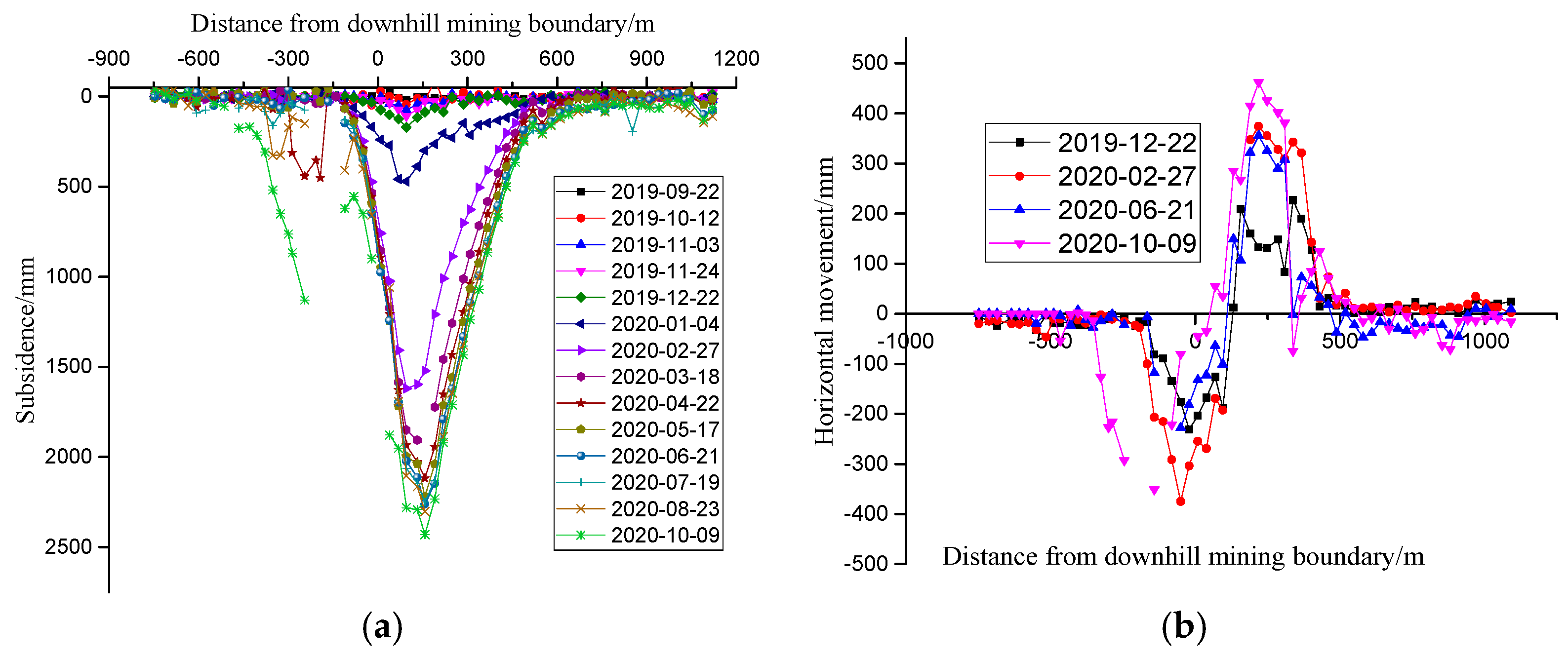
4.2. Surface Subsidence Law along Dip Direction

The obtained subsidence values and horizontal movement values of each period in the dip direction are plotted as follows.
Figure 7a shows the subsidence distribution at different times in the dip direction. It can be seen from the Figure 7a that the surface subsidence value and subsidence range gradually increase with the advance of the working face, the position of the maximum subsidence point remains unchanged, near point B33. By 23 August 2020, the maximum surface subsidence will reach 2307 mm. However, due to the repeated disturbance near the old mining faces on the south sides, the dip subsidence shows the following special laws. Compared with the downhill subsidence curve, the uphill subsidence curve changes more gently and has a wider range.
Figure 7b shows the horizontal movement of the trend line at different times. Traditionally, the horizontal movement curve should be an antisymmetric curve. It can be seen from the figure that the horizontal movement gradually increases with the advance of the working face, but it does not form an inverse symmetry.

4.3. Parameter Analysis of Disturbance Range

The surface disturbance range caused by underground mining is often expressed by boundary angle and movement angle. The boundary angle delineates the outermost disturbance range of the surface. The movement angle delineates the scope of surface damage. The smaller the angle value, the larger the delineated range. According to the characteristics of surface movement in high relief terrain areas, the minimum boundary angle between horizontal movement and subsidence of 10 mm is taken as the final boundary angle. The final movement angle is obtained according to the outermost critical deformation value points of tilt (3 mm/m), curvature (0.2 mm/m2), and horizontal deformation (2 mm/m). The obtained boundary angle and movement angle are shown in Table 5.
Traditionally, the boundary angle is about 55–60°and the moving angle is about 65–70° [30]. It can be seen from Table 5 that the boundary angle and movement angle of the strike line are large, and the influence range of the surface is small. However, the boundary angle and movement angle in the downhill direction are small, and the surface influence range is large.

5. Discussion

The following mainly analyzes the special law of mining-induced surface disturbance from two aspects: surface topography and repeated mining.

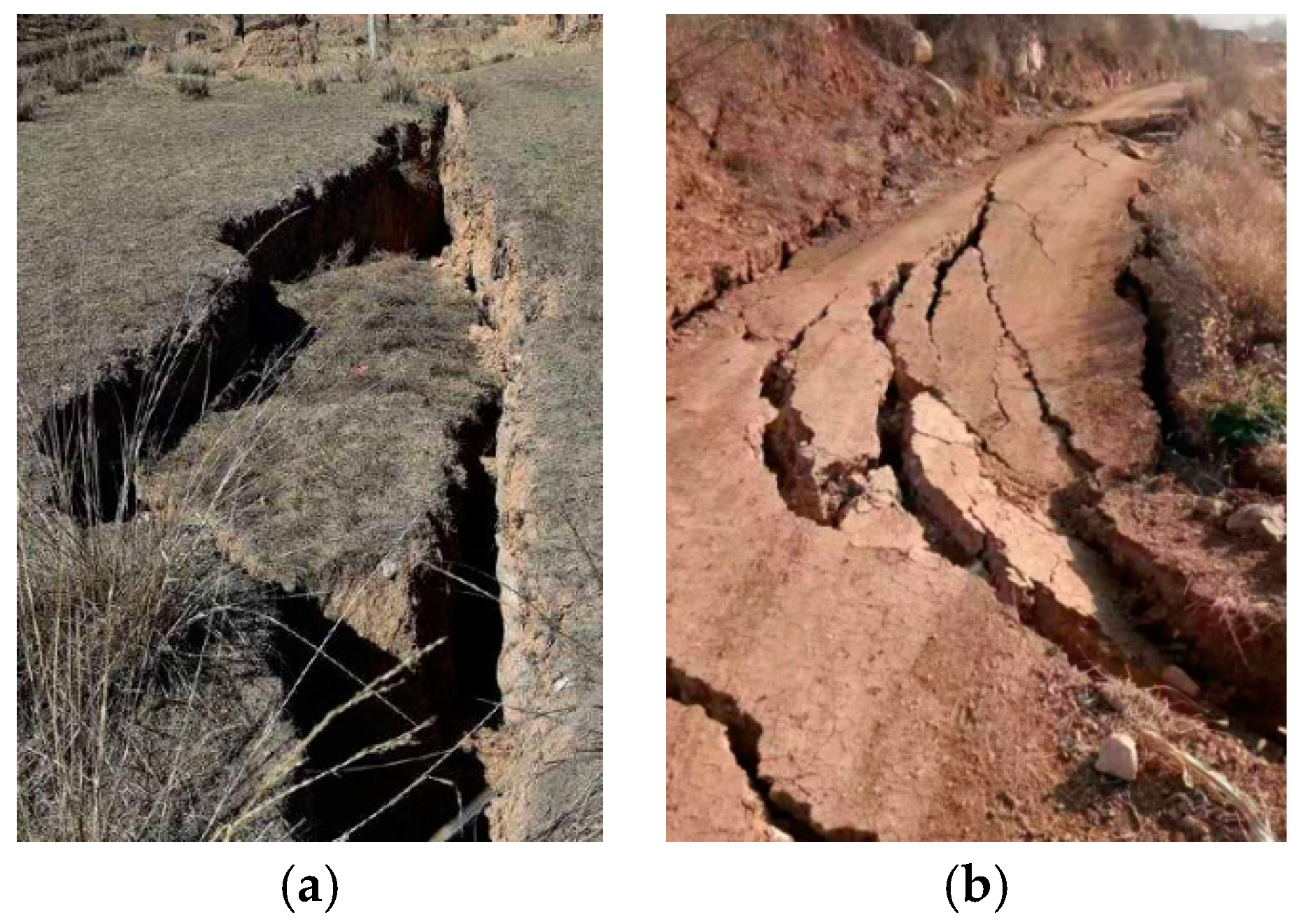
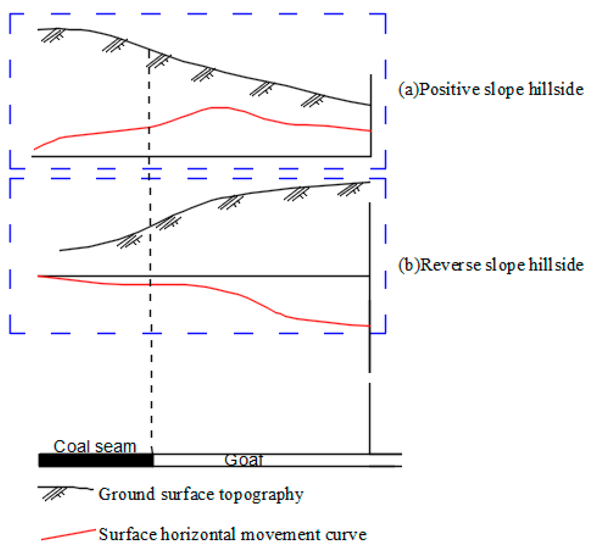
5.1. High Relief Terrain

According to the spatial correspondence between working face distribution and surface topography, high relief terrain can be divided into positive slope and reverse slope. When the ground surface slope inclines to the goaf, the slope is called the positive slope, as shown in Figure 8a. On the contrary, when the ground surface slope tends to the side of the coal pillar, the slope is called reverse slope, as shown in Figure 8b.
According to the general theory of mining subsidence, under the condition of flat terrain, all surface points in the mining affected area move to the goaf, which is called mining-induced surface movement. In addition, under the influence of external action, the slope of high relief terrain will slip itself. Therefore, when the surface terrain is highly relief terrain, the surface movement is the superposition of mining-induced surface movement and surface slope sliding.
(1)
When the terrain directly above the goaf is a positive slope, the sliding direction of the slope itself is consistent with the movement direction of the mining surface. The slope slip will aggravate the surface movement, aggravate the damage degree of surface mining and increase the influence range of mining.
(2)
When the terrain directly above the goaf is an inverse slope, the sliding direction of the slope itself is opposite to the mining surface movement direction. The slope slip will weaken the surface movement and reduce the surface damage degree and the influence range.
The A1–A34 terrain of the working face 1310 is a reverse slope, which reduces the surface damage degree and the influence range of mining, which explains the reason the boundary angle and movement angle of the strike direction are large and the influence range is small. In addition, A35–A49 terrain is a positive slope. When the sliding of the broken body and the movement of the mining surface exceed the anti-sliding ability of the broken body, a large-scale sudden landslide will occur in the broken body, resulting in a sudden increase of the subsidence and horizontal movement in this area. This is the reason for the sudden increase of the subsidence and horizontal movement value at the last few points of the strike observation line.

5.2. Repeated Mining

Working face 1310 is the continuous working face of working face 1309 and 1308. Working face 1310 is mined after 1309 and 1308 have been mined, but the rock stratum movement has not been completed.
In general, the duration of overburden and surface movement after the mining of working face is 1–2 years. The dip observation line of working face 1310 is arranged above the non-mining area in the downhill direction and the mined working faces 1309 and 1308 in the uphill direction. When working face 1310 is mined, the working faces 1309 and 1308 are affected, and the separation layer and gap in the overlying strata are recompressed and transmitted to the surface, resulting in secondary disturbance of the surface. It leads to a wider range of surface disturbance and a larger degree of disturbance in this area. Finally, the boundary angle and movement angle in the downhill direction are small, and the subsidence curve of the inclined observation line is smoother and wider in the downhill direction than that in the uphill direction, which is the reason for the loss of anti-symmetrical characteristics of the dip horizontal movement curve.

6. Conclusions

(1)
In the mining area with high relief terrain, the intervisibility between surface monitoring points is poor, and it is inconvenient to obtain data by traditional measurement methods. This paper presents an improved RTK elevation measurement method, which not only meets the observation accuracy but also improves the observation efficiency.
(2)
Based on the measured data, the special surface disturbance law of the working face 1310 is analyzed. The strike boundary angle and movement angle are large, the boundary angle and movement angle in the downhill direction are small, the dip horizontal movement curve loses its antisymmetry, and the dip subsidence curve loses its left-right symmetry.
(3)
The special surface disturbance law is the result of the combined action of high relief terrain and repeated mining. The high reverse slope reduces the influence range of surface mining and increases the corresponding boundary and movement angle. Landslides occur on high positive slopes, resulting in a sudden increase in subsidence. Repeated mining leads to slower convergence of movement deformation curve, expansion of influence range, and increase of disturbance value.

Author Contributions

Conceptualization, W.Y. (Weitao Yan) and W.Z.; methodology, J.C.; software, W.Y. (Wenfu Yang); validation, W.Y. (Weitao Yan); formal analysis, W.Y. (Wenfu Yang); investigation, X.L.; resources, W.W.; data curation, W.W.; writing—original draft preparation, W.Y. (Weitao Yan) and W.Y. (Wenfu Yang); writing—review and editing, J.C.; visualization, J.C.; supervision, W.Y. (Weitao Yan); project administration, J.C.; funding acquisition, J.C. All authors have read and agreed to the published version of the manuscript.

Funding

This research was funded by the Henan Scientific and Technological Projection grant number (212102310012, 212102310399), the National Natural Science Foundation of China grant number [U21A20108, 51974105, U1810203], the Open Fund of State Key Laboratory of Water Resource Protection and Utilization in Coal Mining grant number (WPUKFJJ2019-20, WPUKFJJ2019-17), the Fundamental Research Funds for the Universities of Henan Province grant number (NSFRF200314), the Youth Backbone Teacher Support Program of Henan Polytechnic University (2019XQG-07), and Doctoral Fund Program of Henan Polytechnic University (B2017-07, B2019-03).

Institutional Review Board Statement

Not applicable.

Informed Consent Statement

Not applicable.

Data Availability Statement

Not applicable.

Conflicts of Interest

The authors declare no conflict of interest.

References

  1. Bell, F.G.; Stacey, T.R.; Genske, D.D. Mining subsidence and its effect on the environment: Some differing example. Environ. Geol. 2000, 40, 135–152. [Google Scholar] [CrossRef]
  2. Saha, S.; Pattanayak, S.; Sills, E. Under-mining health: Environmental justice and mining in India. Health Place 2011, 17, 140–148. [Google Scholar] [CrossRef] [PubMed]
  3. Sasaoka, T.; Takamoto, H.; Shimada, H.; Oya, J.; Hamanaka, A.; Matsui, K. Surface subsidence due to underground mining operation under weak geological condition in Indonesia. J. Rock Mech. Geotech. Eng. 2015, 7, 337–344. [Google Scholar] [CrossRef] [Green Version]
  4. Sinha, S.; Bhattacharya, R.N.; Banerjee, R. Surface iron ore mining in eastern India and local level sustainability. Resour. Policy 2007, 32, 57–68. [Google Scholar] [CrossRef]
  5. Edyta, P.; Wojciech, G.; Ćwiąkała, P.; Wojciech, M. Application of UAV-based orthomosaics for determination of horizontal displacement caused by underground mining. ISPRS J. Photogramm. Remote Sens. 2021, 174, 282–303. [Google Scholar]
  6. Anders, K.; Marx, S.; Boike, J.; Herfort, B.; Wilcox, E.; Langer, M.; Marsh, P.; Höfle, B. Multitemporal terrestrial laser scanning point clouds for thaw subsidence observation at Arctic permafrost monitoring sites. Earth Surf. Process. Landf. 2020, 45, 1589–1600. [Google Scholar] [CrossRef]
  7. Guillaume, M.; Doubre, C.; Masson, F. Time evolution of mining-related residual subsidence monitored over a 24-year period using InSAR in southern Alsace, France. Int. J. Appl. Earth Obs. Geoinf. 2021, 102, 102392. [Google Scholar]
  8. Fan, H.; Wang, L.; Wen, B.; Du, S. A New Model for three-dimensional Deformation Extraction with Single-track InSAR Based on Mining Subsidence Characteristics. Int. J. Appl. Earth Obs. Geoinf. 2020, 94, 102223. [Google Scholar] [CrossRef]
  9. Kim, J.; Lin, S.; Singh, R.; Lan, C.; Yun, H. Underground burning of Jharia coal mine (India) and associated surface deformation using InSAR data. Int. J. Appl. Earth Obs. Geoinf. 2021, 103, 102524. [Google Scholar] [CrossRef]
  10. Carnec, C.; Delacourt, C. Three years of mining subsidence monitored by SAR interferometry, near Gardanne, France. J. Appl. Geophys. 2000, 43, 43–54. [Google Scholar] [CrossRef]
  11. Essica, M.W. Application of DInSAR for short period monitoring of initial subsidence due to longwall mining in the mountain west United States. Int. J. Min. Sci. Technol. 2020, 30, 33–37. [Google Scholar]
  12. Tang, F.-Q. Research on mechanism of mountain landslide due to underground mining. J. Coal Sci. Eng. 2009, 15, 351–354. [Google Scholar] [CrossRef]
  13. Gao, C.; Xu, N.; Sun, W. Dynamic surface subsidence prediction model based on Bertalanffy time function. J. China Coal Soc. 2020, 45, 2740–2748. [Google Scholar]
  14. Dai, H. Mining subsidence variables and their time-space relationship description. J. China Coal Soc. 2018, 43, 450–459. [Google Scholar]
  15. Cui, X.; Gao, Y.; Yuan, D. Sudden surface collapse disasters casused by shallow partial mining in Datong coalfield, China. Nat. Hazards 2014, 74, 911–929. [Google Scholar] [CrossRef]
  16. Li, Q.; Wang, J.; Yang, Q. Application and research on prediction method for mining subsidence in shallow buried deep coal seam. Coal Sci. Technol. 2019, 47, 175–181. [Google Scholar] [CrossRef]
  17. Zhang, H. Study on equivalent calculation method of surface subsidence in inclined coal seam mining. Coal Sci. Technol. 2020, 48, 119–123. [Google Scholar]
  18. Jia, X.; Song, G.; Chen, K. Study on influence of mining face advancing velocity on progressive surface subsidence and deformation. Coal Sci. Technol. 2019, 47, 208–214. [Google Scholar]
  19. Wang, Q.; Li, T.; Guo, G. Study on seam inclination variation affected to ground surface movement law in base rock exposed mountain area. Coal Sci. Technol. 2016, 44, 155–160. [Google Scholar] [CrossRef]
  20. Wang, L.; Guo, G.; Wang, M. New method of updating design for model and its parameter to prediction surface movement in mountainous mining. J. China Coal Soc. 2014, 39, 1070–1076. [Google Scholar]
  21. Han, K.; Kang, J.; Wang, Z. Uniform prediction parameters for ground movement model in mountain area caused by coal mining. J. Min. Saf. Eng. 2013, 30, 107–111. [Google Scholar]
  22. Lian, X.; Hu, H.; Guo, B. Regularities of surface dynamic movement and deformation induced by mining in mountainous area. Met. Min. 2016, 9, 151–156. [Google Scholar]
  23. Zhao, B.; Liang, N.; Wu, C. Prediction system for mining subsidence of steeply inclined coal seam based on matlab in mountainous area. Met. Min. 2020, 03, 159–167. [Google Scholar]
  24. Liu, Y.; Dai, H. A surface subsidence model of coal seam mining in mountain area based on plate bending deformation. Mec. Eng. 2019, 41, 559–564. [Google Scholar]
  25. Dai, H.; Zhai, J.; Hu, Y. Testing study of surface displacement of mountainous region with similar material. Chin. J. Rock Mech. Eng. 2000, 04, 501–504. [Google Scholar]
  26. Bai, G.; Zhang, D.; Zhang, J. Law of surface movement and deformation of mining subsidence in mountain area. J. Liaoning Tech. Univ. 2017, 36, 684–688. [Google Scholar]
  27. Lan, H.; Zhang, H.; Yao, J. Numerical smiulation of mining subsidence predict of mountain surface. J. China Coal Soc. 2007, 9, 912–916. [Google Scholar]
  28. Hu, H.; Lian, X.; Cai, Y. Study on ecological environment damage and restoration for coal mining-subsided area in loess hilly area of Shanxi Province. Coal Sci. Technol. 2020, 48, 70–79. [Google Scholar]
  29. Yi, Z.; Liu, M.; Liu, X.; Wang, Y.; Wu, L.; Wang, Z.; Zhu, L. Long-term Landsat monitoring of mining subsidence based on spatiotemporal variations in soil moisture: A case study of Shanxi Province, China. Int. J. Appl. Earth Obs. Geoinf. 2021, 102, 102447. [Google Scholar] [CrossRef]
  30. Yan, W.; Chen, J.; Tan, Y.; Zhang, W.; Cai, L. Theoretical Analysis of Mining Induced Overburden Subsidence Boundary with the Horizontal Coal Seam Mining. Adv. Civ. Eng. 2021, 3, 6657738. [Google Scholar] [CrossRef]
Figure 1. Surface disturbance and damage under the influence of mining. (a) Mountain crack; (b) mountain road slip crack.
Sustainability 14 03166 g001
Figure 2. Topography of study area.
Sustainability 14 03166 g002
Figure 3. Actual layout point map of observation station.
Sustainability 14 03166 g003
Figure 4. Topographic map. (a) Strike line direction; (b) dip line direction.
Sustainability 14 03166 g004
Figure 5. Layout of the test area and points.
Sustainability 14 03166 g005
Figure 6. Dynamic moving curve of strike direction. (a) Subsidence; (b) horizontal movement.
Sustainability 14 03166 g006
Figure 7. Dynamic moving curve of dip direction. (a) Subsidence; (b) horizontal movement.
Sustainability 14 03166 g007
Figure 8. Positive slope hillside and reverse slope hillside. (a) Positive slope hillside; (b) reverse slope hillside.
Sustainability 14 03166 g008
Table 1. Characteristics of roof and floor strata of coal seam 1310.
Name of Roof and FloorRock NameThickness/mLithologic Characteristics
Main roof Fine grained sandstone6.10Gray, mainly composed of rock debris, intercalated with black organic stripes
Direct roofSandy mudstone10.29Black sandy mudstone, thin layer, with coal line at the top, rich in plant fossils
Direct floorSandy mudstone7.34Grayish black, intercalated with lenticular siltstone, shear joint, unfilled, occasionally vegetated
Main floof Siltstone10.60Dark gray, thin layer, horizontal bedding, intercalated with a small amount of argillaceous strips and a small amount of animal fossils
Table 2. Summary of observation station layout.
Number of Monitoring PointsLength/m
Strike line491440
Dip line661950
In total1153390
Table 3. Experimental result.
Point NumberElevation of Leveling/mRTK Survey Elevation/mAbsolute Value of Elevation Difference/mmFrom the Base Point, the Cumulative Number of Measured Stations Tolerance Requirements for Elevation Survey/mm
A11048.3861048.36224217
A21048.7741048.74826424
A31049.4311049.45625629
A41047.4011047.405−4936
A51049.1081049.139311140
A61048.0971048.112151242
A71047.9951047.968271343
A81049.2081049.21351546
A91049.0991049.076231648
A101048.2141048.242281749
Table 4. Monitoring information.
Observation OrderObservation ContentObservation TimeAdvancing Distance of Working Face
1
2
Coordinate survey + elevation survey5 Septembet 2019
11 Septembet 2019
10~15 days before the mining impact of working face
3Elevation survey22 Septembet 2019Working face advancing 1345 m
4Elevation survey12 October 2019Working face advancing 1414 m
5Elevation survey3 November 2019Working face advancing 1603 m
6Elevation survey24 November 2019Working face advancing 1750 m
7Coordinate survey + elevation survey22 December 2019Working face advancing 1844 m
8Elevation survey4 January 2020Working face advancing 1898 m
8Elevation survey27 February 2020Working face advancing 2163 m
10Elevation survey18 March 2020Working face advancing 2274 m
11Elevation survey22 April 2020Working face advancing 2442 m
12Elevation survey17 May 2020Working face advancing 2559 m
13Coordinate survey + elevation survey21 June 2020End of working face advance
14Elevation survey19 July 2020End of working face advance
15Coordinate survey + elevation survey23 August 2020End of working face advance
16Coordinate survey + elevation survey9 October 2020End of working face advance
Table 5. Boundary angle and movement angle.
Strike Direction/°Dip Direction/°Average
Reverse-Positive Slope Downhill (Reverse Slope)Uphill (Reverse Slope)
Boundary angle63.150.857.757.2
Movement angle72.863.570.669.0
Publisher’s Note: MDPI stays neutral with regard to jurisdictional claims in published maps and institutional affiliations.

